US5704573A - Aperture held clip type fastener - Google Patents
Aperture held clip type fastener Download PDFInfo
- Publication number
- US5704573A US5704573A US08/519,925 US51992595A US5704573A US 5704573 A US5704573 A US 5704573A US 51992595 A US51992595 A US 51992595A US 5704573 A US5704573 A US 5704573A
- Authority
- US
- United States
- Prior art keywords
- pair
- aperture
- fastener
- item
- flexible arcuate
- Prior art date
- Legal status (The legal status is an assumption and is not a legal conclusion. Google has not performed a legal analysis and makes no representation as to the accuracy of the status listed.)
- Expired - Lifetime
Links
- 230000037431 insertion Effects 0.000 claims abstract description 74
- 238000003780 insertion Methods 0.000 claims abstract description 74
- 239000011800 void material Substances 0.000 claims description 13
- 230000000717 retained effect Effects 0.000 claims 5
- 230000001154 acute effect Effects 0.000 description 4
- 238000009434 installation Methods 0.000 description 4
- 239000000463 material Substances 0.000 description 4
- 239000004677 Nylon Substances 0.000 description 1
- 230000003247 decreasing effect Effects 0.000 description 1
- 230000007812 deficiency Effects 0.000 description 1
- 230000009977 dual effect Effects 0.000 description 1
- 239000002184 metal Substances 0.000 description 1
- 239000007769 metal material Substances 0.000 description 1
- 229920001778 nylon Polymers 0.000 description 1
Images


Classifications
-
- F—MECHANICAL ENGINEERING; LIGHTING; HEATING; WEAPONS; BLASTING
- F16—ENGINEERING ELEMENTS AND UNITS; GENERAL MEASURES FOR PRODUCING AND MAINTAINING EFFECTIVE FUNCTIONING OF MACHINES OR INSTALLATIONS; THERMAL INSULATION IN GENERAL
- F16L—PIPES; JOINTS OR FITTINGS FOR PIPES; SUPPORTS FOR PIPES, CABLES OR PROTECTIVE TUBING; MEANS FOR THERMAL INSULATION IN GENERAL
- F16L3/00—Supports for pipes, cables or protective tubing, e.g. hangers, holders, clamps, cleats, clips, brackets
- F16L3/08—Supports for pipes, cables or protective tubing, e.g. hangers, holders, clamps, cleats, clips, brackets substantially surrounding the pipe, cable or protective tubing
- F16L3/12—Supports for pipes, cables or protective tubing, e.g. hangers, holders, clamps, cleats, clips, brackets substantially surrounding the pipe, cable or protective tubing comprising a member substantially surrounding the pipe, cable or protective tubing
- F16L3/13—Supports for pipes, cables or protective tubing, e.g. hangers, holders, clamps, cleats, clips, brackets substantially surrounding the pipe, cable or protective tubing comprising a member substantially surrounding the pipe, cable or protective tubing and engaging it by snap action
-
- F—MECHANICAL ENGINEERING; LIGHTING; HEATING; WEAPONS; BLASTING
- F16—ENGINEERING ELEMENTS AND UNITS; GENERAL MEASURES FOR PRODUCING AND MAINTAINING EFFECTIVE FUNCTIONING OF MACHINES OR INSTALLATIONS; THERMAL INSULATION IN GENERAL
- F16L—PIPES; JOINTS OR FITTINGS FOR PIPES; SUPPORTS FOR PIPES, CABLES OR PROTECTIVE TUBING; MEANS FOR THERMAL INSULATION IN GENERAL
- F16L3/00—Supports for pipes, cables or protective tubing, e.g. hangers, holders, clamps, cleats, clips, brackets
- F16L3/22—Supports for pipes, cables or protective tubing, e.g. hangers, holders, clamps, cleats, clips, brackets specially adapted for supporting a number of parallel pipes at intervals
- F16L3/237—Supports for pipes, cables or protective tubing, e.g. hangers, holders, clamps, cleats, clips, brackets specially adapted for supporting a number of parallel pipes at intervals for two pipes
Definitions
- the subject invention relates generally to fasteners for gripping and holding items such as lines, wires, conduits, and the like, which items may have a circular cross section.
- the invention also relates to fasteners which are inserted into an aperture in a support panel, such as a sheet panel of an automobile, for retaining the gripped item in a semi-permanent location adjacent the panel.
- fasteners have been proposed for gripping and holding, in a semi-permanent position, items such as wires or cables.
- Some of the prior fasteners are formed from a semi-flexible material, and are an arranged to be affixed to a panel by inserting a portion of the fastener through an aperture.
- deficiencies in the prior art have been recognized.
- the prior art does not disclose a simple clip structure which would first facilitate the insertion of an item into the clip while the clip is in a pre-installed relaxed state, and then, upon installation of the clip into an aperture of a panel, act to grip and hold the item in a semi-permanent position.
- the present invention relates to the solution of the problem of providing a clip type fastener which first facilitates the insertion of an item into a fastener so as to be gripped and held by the fastener, which item may be of generally circular cross-section, and then upon insertion of the fastener into an aperture of a panel, acts to grip and hold the item in a semi-permanent position.
- One object of the invention is to provide an efficient fastener structure which, in the pre-installed state, provides surfaces for guiding the item to be held into the fastener.
- Another object of the invention is to provide a reliable structure which changes its geometry upon insertion into an aperture of a panel so as to more securely grip the item after the fastener is inserted into the panel.
- FIG. 1 is a side view of a first embodiment of the invention in the pre-installed state.
- FIG. 2 is a side view of a first embodiment of the invention in the installed state.
- FIG. 3 is a side view of a second embodiment of the invention in the pre-installed state.
- FIG. 4 is a side view of a second embodiment of the invention in the
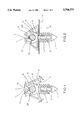
- FIG. 5 is a side view of a third embodiment of the invention wherein the left side of the FIGURE shows the fastener of the invention in the installed state as noted by the dotted lines thereof, while the right side of the FIGURE shows the fastener in the pre-installed state.
- a first embodiment of the invention is shown, in the pre-installed state.
- This embodiment comprises a panel insertion tip 1 and shaft 2 which are inserted into an aperture of a panel, such as a sheet metal panel of an automobile.
- the shaft may contain anti-retraction ribs 3 at various locations along the shaft 2.
- the fastener is made of a semi-flexible material such as nylon. Other equivalent metallic and non-metallic materials may also be utilized.
- the fastener may comprise at least two arcuate lever arms 4, each extending outwardly from the centerline of the shaft 2, in a slightly concave manner around the point at which the shaft 2 meets the arcuate lever arms 4.
- the arcuate lever arms 4 are at substantially right angles to the shaft 2. Other angular configurations are also possible according to the invention. Near the origin of each of the arcuate lever arms 4 is a flex point 6 which controls and limits the movement of each of the arcuate lever arms 4 in a direction generally longitudinal with respect to a centerline of the shaft 2.
- each arcuate lever arm 4 Extending from a terminal point of each arcuate lever arm 4 to a point generally distal from the panel insertion tip 1 is a side lever arm 5.
- Each of the side lever arms 5 extends generally upwardly so as to meet a side wall 25.
- the side walls 25 extend from the meeting point with the side lever arms 5, in a direction generally longitudinal with respect to the center line of the shaft 2, downwardly to the flex point 6.
- the general shape formed by the arcuate lever arm 4, the side lever arm 5, and the side wall 25 may be triangular. Other shapes and relationships are also possible according to the invention.
- a seating surface 8 is provided for receiving a gripped item 7, shown in the drawings as having a generally circular cross-section. Other cross-sectional shapes are possible depending on the application.
- a gripped item 7 may be inserted by pressing the gripped item 7 into a gripped item void 9 from a point distal from the panel insertion tip 1.
- at least two protrusion fingers 10 extend from the meeting point of the side lever arm 5 and the side wall 25, back towards the panel insertion tip 1, at an acute angle with respect to the centerline of the shaft 2. This angle may vary, depending on the flexibility of the fastener material, the flexibility and site of the gripped item 7, the frictional characteristics of the fastener and the gripped item 7, and other factors.
- Each of the protrusion fingers 10 terminate at a point in the gripped item void 9.
- the protrusion fingers 10 each exhibit an insertion surface 11, which viewed from the side together generally form a "V" shape, to facilitate insertion of the gripped item 7.
- the distal end of each protrusion finger 10 may have a protrusion grip surface 13 which acts to restrain the gripped item 7 in the gripped item void 9.
- Panel insertion tip 1 which may have a generally pointed shape to aid insertion, and shaft 2 are inserted into an aperture in panel 12.
- Anti-retraction ribs 3 which may be angled in a direction away from panel insertion tip 1, act to facilitate installation of the shaft 2, but thereafter oppose withdrawal of the shaft 2 from the aperture.
- arcuate lever arms 4 Upon complete insertion of shaft 2 into the panel aperture, arcuate lever arms 4 are moved by the panel to a less arcuate, less concave shape.
- the arcuate lever arms 4 may act to create a resilient force which tends to urge the shaft 2 out of the aperture, which movement may be resisted on the other side of the panel 12 by the anti-retraction ribs 3. These offsetting forces may act to hold the fastener firmly against the panel 12. However, this is not the sole function of the arcuate lever arms 4.
- each of the arcuate lever arms 4 flexes at flex point 6, acting on the respective side lever arms 5, side walls 25, and protrusion fingers 10 in a manner which tends to move the protrusion grip surfaces 13 closer to the gripped item 7, to hold the gripped item 7 securely within the gripped item void 9.
- the protrusion grip surfaces 13 are moved against the gripped item 7, urging the gripped item 7 against the seating surface 8.
- the protrusion fingers 10 serve the dual purpose of first facilitating insertion of the gripped item 7 into the fastener, and then, upon insertion of the fastener into a panel 12, acting to hold the gripped item 7 in the desired location.
- FIG. 3 a further embodiment of the fastener is shown in the pre-installation state.
- a panel insertion tip 1, shaft 2, and anti-retraction ribs 3 are shown.
- At least two free arcuate lever arms 26 are shown extending away from and at substantially right angles to the shaft 2.
- the free arcuate lever arms 26 may extend outwardly from the centerline of the shaft 2, in a slightly concave manner around the point at which the shaft 2 meets the free arcuate lever arms 26.
- a notched flex point 27 Adjacent the lever arm protrusion 14, nearer to the centerline of the shaft 2, is a notched flex point 27.
- a generally semi-circular side oriented seating surface 28 extends through an arc from a point near the notched flex point 27 to a point substantially 180° from the notched flex point 27.
- the side oriented seating surface 28 is contained within a side element 29.
- the shape of side element 29 may correspond with or be divergent from the shape of the side oriented seating surface 28.
- the side element 29 may in one embodiment extend from the notched flex point 27 to a point substantially 180° from the notched flex point 27, and then extend into a side element extension 30 which may be arranged at substantially 90° with respect to the centerline of the shaft 2.
- the side element extension 30 extends away from the centerline of shaft 2 to a point at which it changes direction and extends into a protrusion finger 10.
- the protrusion finger 10 extends back towards the centerline of shaft 2 at an acute angle with respect to the centerline of shaft 2, and terminates with a protrusion grip surface 13.
- the interior surfaces of the side element 29, side element extension 30, and protrusion finger 10 define a gripped item void 9.
- the lever arm protrusion 14 and the protrusion finger 10 present protrusion surfaces 31 and insertion surface 11, respectively. Surfaces 31 and 11 may form a general "V" shape which points toward the centerline of the shaft 2 along a line which is substantially 90° with respect to the centerline of the shaft 2.
- the resulting structure allows insertion of a gripped item 7 in a direction along a line which is at substantially right angles to the centerline of the shaft 2.
- the lever arm protrusion 14, protrusion finger 10, and the corresponding surfaces 31 and 11, respectively, facilitate insertion of a gripped item 12.
- the side element 29, side element extension 30, and protrusion finger 10 are formed from a semi-flexible material which flexes to accept a gripped item 7.
- the fastener is shown in an installed state.
- panel insertion tip 1, shaft 2, and anti-retraction ribs 3 have been inserted into an aperture of a panel 12, whereby the panel 12 exerts a force against free arcuate lever arms 26 which urges them into a less arcuate configuration.
- notched flex point 27 flexes and tends to close as a result of the movement of the free arcuate lever arms 26, lever arm protrusion 14 moves toward the gripped item 7, and in one embodiment, lever arm protrusion grip surface 14 is urged against the gripped item 7, holding it in place against the side oriented seating surface 28.
- the fastener is shown in an uninstalled and also an installed state.
- two gripped items 7 may be held by a single fastener, as gripping means may be provided on both sides of a centerline of shaft 2.
- the fastener of the present embodiment may have a panel insertion tip 1, a shaft 2, and anti-retraction ribs 3.
- Lower lever arms 16 extend away from the shaft 2 at an acute angle with respect to the centerline of shaft 2, angling toward the panel insertion tip 1.
- a lower flex point 19 is formed at the base of the lower lever arm 16, at the point at which the lower lever arm 16 meets the shaft 2.
- the lower lever arm 16 extends to a distal point, and then reverses direction back toward the shaft 2, at distal flex point 20, extending into upper lever arm 17, which terminates with a curved or angled upper lever arm seating surface 24.
- Center spine 32 extends from shaft 2 along the same line, and then splits into two top arm elements 33. Each of the top arm elements 33 extend away from the centerline of shaft 2, in directions opposite each other, at an angle substantially 90° with respect to the centerline of shaft 2.
- Upper flex points 18 are formed at the point where the top arms 33 begin to extend away from the center spine 32. Top arms 33 extend to a distal point, and then turn back towards the center spine 32 at an acute angle with respect to the centerline of the center spine 32, extending into outer retaining arms 21, and terminating in outer retaining arm seating surfaces 22.
- An upper seating surface 23 is formed along the inside of top arm 33.
- a gripped item void 9 is defined by the upper seating surface 23, the upper lever arm seating surface 24 which may be concave, the inside surface of the outer retaining arm 21, and the outer retaining arm seating surface 22.
- the outer retaining arms 21 and upper lever arms 17 exhibit outer retaining arm insertion surfaces 34 and upper lever arm insertion surfaces 35, respectively. These surfaces 34 and 35 generally form a "V" shape which points towards the center spine 32 along a line which is substantially 90° with respect to the centerline of the shaft 2.
- Surfaces 34 and 35 guide an item 7 to be gripped as it is pressed into the gripped item void 9 in a direction along a line which is at substantially right angles to the centerline of the shaft 2.
- a gripped item 7 is inserted into the gripped item void 9, and may contact one or more of the upper lever arm seating surface 24, upper seating surface 23, and outer retaining arm seating surface 22.
- the anti-retraction fibs 3 act to oppose the force exerted against the panel 12 as the lower lever arms 16 flex at lower flex points 19.
- Upper lever arm 17 also flexes at distal flex point 20, thereby decreasing the opening through which the gripped item 7 was originally introduced into the gripped item void 9, and also increasing the force exerted by one or more of the upper lever arm seating surfaces 24, upper seating surfaces 23, and upper retaining arm seating surfaces 22 against the gripped items 7.
Landscapes
- Engineering & Computer Science (AREA)
- General Engineering & Computer Science (AREA)
- Mechanical Engineering (AREA)
- Insertion Pins And Rivets (AREA)
- Professional, Industrial, Or Sporting Protective Garments (AREA)
- Adornments (AREA)
- Supports For Pipes And Cables (AREA)
- Clamps And Clips (AREA)
- Connection Of Plates (AREA)
Priority Applications (5)
| Application Number | Priority Date | Filing Date | Title |
|---|---|---|---|
| US08/519,925 US5704573A (en) | 1995-08-28 | 1995-08-28 | Aperture held clip type fastener |
| CA002181408A CA2181408C (en) | 1995-08-28 | 1996-07-17 | Aperture held clip type fastener |
| IT96TO000707A IT1284755B1 (it) | 1995-08-28 | 1996-08-20 | Elemento di fissaggio del tipo ad apertura trattenuta a scatto. |
| MX9603695A MX9603695A (es) | 1995-08-28 | 1996-08-27 | Sujetador tipo presilla, sostenido mediante abertura. |
| US08/799,320 US5765787A (en) | 1995-08-28 | 1997-02-13 | Aperture held clip type fastener |
Applications Claiming Priority (1)
| Application Number | Priority Date | Filing Date | Title |
|---|---|---|---|
| US08/519,925 US5704573A (en) | 1995-08-28 | 1995-08-28 | Aperture held clip type fastener |
Related Child Applications (1)
| Application Number | Title | Priority Date | Filing Date |
|---|---|---|---|
| US08/799,320 Division US5765787A (en) | 1995-08-28 | 1997-02-13 | Aperture held clip type fastener |
Publications (1)
| Publication Number | Publication Date |
|---|---|
| US5704573A true US5704573A (en) | 1998-01-06 |
Family
ID=24070415
Family Applications (2)
| Application Number | Title | Priority Date | Filing Date |
|---|---|---|---|
| US08/519,925 Expired - Lifetime US5704573A (en) | 1995-08-28 | 1995-08-28 | Aperture held clip type fastener |
| US08/799,320 Expired - Lifetime US5765787A (en) | 1995-08-28 | 1997-02-13 | Aperture held clip type fastener |
Family Applications After (1)
| Application Number | Title | Priority Date | Filing Date |
|---|---|---|---|
| US08/799,320 Expired - Lifetime US5765787A (en) | 1995-08-28 | 1997-02-13 | Aperture held clip type fastener |
Country Status (4)
| Country | Link |
|---|---|
| US (2) | US5704573A (it) |
| CA (1) | CA2181408C (it) |
| IT (1) | IT1284755B1 (it) |
| MX (1) | MX9603695A (it) |
Cited By (62)
| Publication number | Priority date | Publication date | Assignee | Title |
|---|---|---|---|---|
| US5846017A (en) * | 1996-08-29 | 1998-12-08 | Illinois Tool Works Inc. | Sidewinder clip |
| DE19742727A1 (de) * | 1997-09-26 | 1999-04-01 | Andreas Boettcher | Halteelement für flexible Heizungsrohre zur Ausstattung von mit profilierten Blechen gebildeten Wand- und Bodenkonstruktionen |
| US5921511A (en) * | 1997-02-26 | 1999-07-13 | Lapointe; Leo | Soffit clip for retaining a set of decorative lights under the eave of a roof |
| US6062516A (en) * | 1997-04-30 | 2000-05-16 | Atoma International Inc. | Cable clip movement restrictor |
| FR2799521A1 (fr) * | 1999-10-08 | 2001-04-13 | Coutier Moulage Gen Ind | Agrafe de fixation d'un cable sur un organe de commande |
| US6216986B1 (en) | 1999-10-18 | 2001-04-17 | Illinois Tool Works Inc. | Clip with flexible locking arms |
| US6238157B1 (en) | 2000-03-22 | 2001-05-29 | Lear Corporation | Attachment connection for vehicle trim component |
| US6398169B1 (en) * | 1998-04-03 | 2002-06-04 | Sofanou S.A. | Device for securing longitudinal elements on a panel and tool for installing the same |
| US6554232B1 (en) * | 1999-11-04 | 2003-04-29 | International Truck Intellectual Property Company, L.L.C. | Tube clip |
| US20050001213A1 (en) * | 2003-05-12 | 2005-01-06 | The Regents Of The University Of California | Lithium-drifted silicon detector with segmented contacts |
| US6926237B2 (en) | 2003-05-29 | 2005-08-09 | Illinois Tool Works Inc. | Vibration damping clip |
| US7100808B2 (en) * | 1999-12-14 | 2006-09-05 | Stearns Inc. | Multiple use base holder system |
| US20070102594A1 (en) * | 2005-07-28 | 2007-05-10 | Geiger Gerard G | Flush mount connector clip |
| US7240880B2 (en) | 2004-05-13 | 2007-07-10 | Illinois Tool Works Inc | Holding clip |
| US20070234678A1 (en) * | 2006-03-30 | 2007-10-11 | Trw Automotive U.S. Llc | Retainer |
| US20080296444A1 (en) * | 2005-07-28 | 2008-12-04 | Hellermanntyton Corporation | Harness clamp tie |
| US20090307883A1 (en) * | 2008-06-11 | 2009-12-17 | Newfrey Llc | Fastening element to be fastened in a hole |
| US20110010900A1 (en) * | 2008-02-19 | 2011-01-20 | Toscana Gomma S.P.A. | Hook for attaching a sheet material to a mould-formed body |
| US20110268413A1 (en) * | 2010-04-30 | 2011-11-03 | Cote Monique L | Rotatable Routing Guide and Assembly |
| US20120045665A1 (en) * | 2010-08-17 | 2012-02-23 | Samsung Sdi Co., Ltd. | Battery pack |
| USD658053S1 (en) * | 2011-08-12 | 2012-04-24 | Douglas Okun | Conduit clamp |
| US8699838B2 (en) | 2009-05-14 | 2014-04-15 | Ccs Technology, Inc. | Fiber optic furcation module |
| US8712206B2 (en) | 2009-06-19 | 2014-04-29 | Corning Cable Systems Llc | High-density fiber optic modules and module housings and related equipment |
| US8718436B2 (en) | 2010-08-30 | 2014-05-06 | Corning Cable Systems Llc | Methods, apparatuses for providing secure fiber optic connections |
| US8913866B2 (en) | 2010-03-26 | 2014-12-16 | Corning Cable Systems Llc | Movable adapter panel |
| US8953924B2 (en) | 2011-09-02 | 2015-02-10 | Corning Cable Systems Llc | Removable strain relief brackets for securing fiber optic cables and/or optical fibers to fiber optic equipment, and related assemblies and methods |
| US8965168B2 (en) | 2010-04-30 | 2015-02-24 | Corning Cable Systems Llc | Fiber management devices for fiber optic housings, and related components and methods |
| US8989547B2 (en) | 2011-06-30 | 2015-03-24 | Corning Cable Systems Llc | Fiber optic equipment assemblies employing non-U-width-sized housings and related methods |
| US8985862B2 (en) | 2013-02-28 | 2015-03-24 | Corning Cable Systems Llc | High-density multi-fiber adapter housings |
| US8995812B2 (en) | 2012-10-26 | 2015-03-31 | Ccs Technology, Inc. | Fiber optic management unit and fiber optic distribution device |
| US8992099B2 (en) | 2010-02-04 | 2015-03-31 | Corning Cable Systems Llc | Optical interface cards, assemblies, and related methods, suited for installation and use in antenna system equipment |
| US9008485B2 (en) | 2011-05-09 | 2015-04-14 | Corning Cable Systems Llc | Attachment mechanisms employed to attach a rear housing section to a fiber optic housing, and related assemblies and methods |
| US9020320B2 (en) | 2008-08-29 | 2015-04-28 | Corning Cable Systems Llc | High density and bandwidth fiber optic apparatuses and related equipment and methods |
| US9022814B2 (en) | 2010-04-16 | 2015-05-05 | Ccs Technology, Inc. | Sealing and strain relief device for data cables |
| US9038832B2 (en) | 2011-11-30 | 2015-05-26 | Corning Cable Systems Llc | Adapter panel support assembly |
| US9042702B2 (en) | 2012-09-18 | 2015-05-26 | Corning Cable Systems Llc | Platforms and systems for fiber optic cable attachment |
| US9059578B2 (en) | 2009-02-24 | 2015-06-16 | Ccs Technology, Inc. | Holding device for a cable or an assembly for use with a cable |
| US9075217B2 (en) | 2010-04-30 | 2015-07-07 | Corning Cable Systems Llc | Apparatuses and related components and methods for expanding capacity of fiber optic housings |
| US20150274008A1 (en) * | 2014-03-27 | 2015-10-01 | Toyoda Gosei Co., Ltd. | Fuel feeding device for vehicles |
| US9213161B2 (en) | 2010-11-05 | 2015-12-15 | Corning Cable Systems Llc | Fiber body holder and strain relief device |
| US9250409B2 (en) | 2012-07-02 | 2016-02-02 | Corning Cable Systems Llc | Fiber-optic-module trays and drawers for fiber-optic equipment |
| US20160047494A1 (en) * | 2009-05-13 | 2016-02-18 | Termax Corporation | Magnetic Cable Fastener |
| US9279951B2 (en) | 2010-10-27 | 2016-03-08 | Corning Cable Systems Llc | Fiber optic module for limited space applications having a partially sealed module sub-assembly |
| JP2016125642A (ja) * | 2015-01-08 | 2016-07-11 | クボタシーアイ株式会社 | パイプ保持具 |
| US9453594B2 (en) * | 2014-01-07 | 2016-09-27 | Itw Fastener Products Gmbh | Fixing device |
| US9519118B2 (en) | 2010-04-30 | 2016-12-13 | Corning Optical Communications LLC | Removable fiber management sections for fiber optic housings, and related components and methods |
| US20170042032A1 (en) * | 2014-04-08 | 2017-02-09 | Samsung Electronics Co., Ltd. | Clamp and display device including same |
| US20170089491A1 (en) * | 2015-09-25 | 2017-03-30 | Toyoda Gosei Co., Ltd. | Fuel supply apparatus |
| US9645317B2 (en) | 2011-02-02 | 2017-05-09 | Corning Optical Communications LLC | Optical backplane extension modules, and related assemblies suitable for establishing optical connections to information processing modules disposed in equipment racks |
| US9828151B2 (en) * | 2013-02-28 | 2017-11-28 | Kitagawa Industries Co., Ltd. | Securing mechanism |
| US10094996B2 (en) | 2008-08-29 | 2018-10-09 | Corning Optical Communications, Llc | Independently translatable modules and fiber optic equipment trays in fiber optic equipment |
| US20180364435A1 (en) * | 2014-09-16 | 2018-12-20 | CommScope Connectivity Belgium BVBA | Rotatable patch cable holder |
| US10202787B2 (en) * | 2016-08-23 | 2019-02-12 | Inteva Products, Llc | Retaining feature for an adjustment rod clip |
| KR101992567B1 (ko) * | 2018-07-18 | 2019-06-24 | 이정수 | 케이블 체적 적응형 바 타입 케이블 정리장치 |
| KR101992568B1 (ko) * | 2018-07-18 | 2019-09-30 | 이정수 | 케이블 체적 적응형 자바라 타입 케이블 정리장치 |
| US11294136B2 (en) | 2008-08-29 | 2022-04-05 | Corning Optical Communications LLC | High density and bandwidth fiber optic apparatuses and related equipment and methods |
| US20250060082A1 (en) * | 2023-08-14 | 2025-02-20 | Hella Saturnus Slovenija d.o.o. | Clamping means for a light guide element and light guide element arrangement with such a clamping means |
| DE102023129101A1 (de) * | 2023-10-23 | 2025-04-24 | Yazaki Systems Technologies Gmbh | Routerclip, Kabelbaum und Verfahren zur Herstellung des Kabelbaums |
| US12326210B2 (en) | 2022-03-24 | 2025-06-10 | Hellermanntyton Corporation | Quick attach clamp |
| US12338848B2 (en) | 2022-06-30 | 2025-06-24 | Hellermanntyton Corporation | Anti-wobble fir tree mount |
| US12460749B2 (en) | 2023-04-28 | 2025-11-04 | Hellermanntyton Corporation | Cradle mount fixings |
| DE102024204340A1 (de) * | 2024-05-08 | 2025-11-13 | Volkswagen Aktiengesellschaft | Befestigungsvorrichtung und Kraftfahrzeug |
Families Citing this family (28)
| Publication number | Priority date | Publication date | Assignee | Title |
|---|---|---|---|---|
| US6065899A (en) * | 1997-10-27 | 2000-05-23 | Adam Mfg. Corp. | Stake system |
| JP3960677B2 (ja) * | 1998-02-16 | 2007-08-15 | 株式会社ニフコ | 棒状物保持具 |
| US6148488A (en) * | 1998-09-14 | 2000-11-21 | Gristock; Rick Alan | Pipe clip type flexible-sheet fastening device |
| US6068048A (en) * | 1999-03-09 | 2000-05-30 | American Standard Inc. | Wire harness retainer for spine fin air conditioning coils |
| NL1012069C2 (nl) * | 1999-05-17 | 2000-11-20 | Buhrs Zaandam Bv | Klem voor het vastzetten van een onderdeel op een staaf alsmede een document-aanvoerinrichting voorzien van ten minste ÚÚn dergelijke klem. |
| JP3682698B2 (ja) * | 1999-06-04 | 2005-08-10 | 株式会社パイオラックス | 棒状体ホルダー |
| US6536718B2 (en) * | 2001-01-11 | 2003-03-25 | Aparellaje Electrico, S.L. | Pressure plug for supporting electric cables |
| US6669150B2 (en) | 2001-05-31 | 2003-12-30 | Illinois Tool Works Inc. | Clip assembly with positive locating features |
| US6899304B2 (en) * | 2002-04-11 | 2005-05-31 | Ligon Brothers Manufacturing | Method for forming a fastener |
| DE20208280U1 (de) * | 2002-05-27 | 2003-10-09 | Nölle-Pepin GmbH & Betriebs KG, 58332 Schwelm | Halteteil zur Anbringung von Metallrahmennetzen, insbesondere von Kofferraumseitennetzen |
| ITTO20040088A1 (it) * | 2004-02-17 | 2004-05-17 | Itw Automotive Italia S R L | Elemento di ritegno a fascetta per componenti assialsimmetrici quali cavi o tubetti, in particolare per l'applicazione su veicoli |
| DE102005026471B4 (de) * | 2005-06-09 | 2008-05-08 | Itw Automotive Products Gmbh & Co. Kg | Halter für eine Leitung in einem Automobil |
| DE102008009020A1 (de) * | 2008-02-13 | 2009-08-20 | Rosen Swiss Ag | Haltevorrichtung für Rohre, Kabel oder dergleichen stangenförmiges Gut |
| JP2010000256A (ja) * | 2008-06-20 | 2010-01-07 | Fujitsu Component Ltd | 脈拍検出装置およびその製造方法 |
| US7896601B2 (en) * | 2009-01-22 | 2011-03-01 | Marimba Auto, Llc | Two-piece Fastener |
| DE102009017977A1 (de) * | 2009-04-21 | 2010-10-28 | Airbus Deutschland Gmbh | Haltevorrichtung für innerhalb eines Flugzeugrumpfs verlegte Anbauteile |
| USD679177S1 (en) | 2009-05-08 | 2013-04-02 | Zsi, Inc. | Combined clip device and support for elongated members |
| USD631739S1 (en) * | 2009-05-08 | 2011-02-01 | Zsi, Inc. | Combined clip device and support for elongated members |
| JP2012231558A (ja) * | 2011-04-25 | 2012-11-22 | Sumitomo Wiring Syst Ltd | クリップ及びクリップ付ワイヤハーネス |
| FR2981416B1 (fr) * | 2011-10-13 | 2013-12-20 | Acl Sport Nature | Dispositif de fixation d'un filet comportant un surjetage a un support |
| US10208780B1 (en) * | 2017-05-16 | 2019-02-19 | Peter G. Mangone, Jr. | Line mounting device |
| FR3070194A1 (fr) * | 2017-08-16 | 2019-02-22 | Psa Automobiles Sa | Transmission d'un vehicule automobile comprenant un support de fixation d’un cable electrique |
| DE102018123954B4 (de) | 2018-09-27 | 2023-08-03 | Langmatz Gmbh | Haltevorrichtung, Halterungsgerüst sowie Glasfaserverteilereinrichtung |
| JP7120094B2 (ja) * | 2019-03-15 | 2022-08-17 | 豊田合成株式会社 | 車両用パイプ保持具 |
| FR3099535B1 (fr) * | 2019-08-01 | 2021-11-05 | Sarl Francois Inglese | Dispositif de fixation d’au moins un tube contre une paroi |
| FR3099534B1 (fr) * | 2019-08-01 | 2021-12-17 | Francois Inglese | Dispositif de fixation d’au moins un tube contre une paroi |
| US11867216B2 (en) * | 2020-06-04 | 2024-01-09 | Hando Kim | Compliant self-anchoring screw with auxetic properties |
| FR3147608A1 (fr) * | 2023-04-05 | 2024-10-11 | Delfingen Industry S.A. | Dispositif de retenue pour objet cylindrique |
Citations (26)
| Publication number | Priority date | Publication date | Assignee | Title |
|---|---|---|---|---|
| US1668953A (en) * | 1926-04-10 | 1928-05-08 | Frederic W Erickson | Molding for electric cables |
| US1906874A (en) * | 1931-12-26 | 1933-05-02 | Arthur I Platt | Implement holder |
| US2891296A (en) * | 1955-05-09 | 1959-06-23 | American Machine & Metals | Clamp |
| US3080140A (en) * | 1961-06-26 | 1963-03-05 | Electrical Fittings Corp | Clamp for conduit or the like |
| FR1401899A (fr) * | 1964-07-22 | 1965-06-04 | Raymond A | Bouchon en matière plastique pour perçages dans des parois de carrosserie ou d'appareils, destiné à la fixation d'accessoires |
| US3313009A (en) * | 1965-03-12 | 1967-04-11 | Beckson Mfg Inc | Spring clip |
| US3430904A (en) * | 1966-12-19 | 1969-03-04 | Illinois Tool Works | Fastening device |
| US3441986A (en) * | 1967-08-31 | 1969-05-06 | Robin Products Co | Fastening clip |
| US3521332A (en) * | 1968-03-04 | 1970-07-21 | Roy G Kramer | Double ended clip |
| US3584348A (en) * | 1970-02-04 | 1971-06-15 | Illinois Tool Works | Spring clip |
| US3659319A (en) * | 1970-11-30 | 1972-05-02 | Lloyd A Erickson | Adhesive wire routing clip |
| US3807675A (en) * | 1971-07-09 | 1974-04-30 | Trw Inc | Fastener |
| US3916089A (en) * | 1974-06-10 | 1975-10-28 | Envirotech Corp | Bracket for conductors |
| US4244544A (en) * | 1978-05-30 | 1981-01-13 | Ford Motor Company | Holders for cables and conduits |
| US4358080A (en) * | 1979-11-06 | 1982-11-09 | A. Raymond | Fastener clip for detachably securing functional components to threaded pins fixed to a support plate |
| US4442991A (en) * | 1982-02-08 | 1984-04-17 | Levens Dennis L | Cradle for stowing cylindrical tank |
| US4450605A (en) * | 1981-05-06 | 1984-05-29 | Usm Corporation | Pipe clip |
| US4550891A (en) * | 1982-10-15 | 1985-11-05 | Usm Corporation | Plastic pipe clip |
| US4566660A (en) * | 1983-01-20 | 1986-01-28 | National Molding Corporation | Cradle clip |
| US4614321A (en) * | 1984-04-30 | 1986-09-30 | A. Raymond | Pipe clip |
| US4669688A (en) * | 1985-02-07 | 1987-06-02 | Kitagawa Industries Co., Ltd. | Cable clamp |
| GB2221718A (en) * | 1988-08-10 | 1990-02-14 | Kitagawa Ind Co Ltd | Wire clamp |
| US4958791A (en) * | 1986-09-17 | 1990-09-25 | Shinagawa Shoko Co., Ltd. | Tying means |
| US5039040A (en) * | 1989-06-13 | 1991-08-13 | Itw De France | Snap-fastener |
| US5316245A (en) * | 1991-10-25 | 1994-05-31 | Trw United Carr Gmbh & Co., Kg | Plastic holding element |
| US5346165A (en) * | 1989-08-02 | 1994-09-13 | Robert George Frean | Restraining device |
-
1995
- 1995-08-28 US US08/519,925 patent/US5704573A/en not_active Expired - Lifetime
-
1996
- 1996-07-17 CA CA002181408A patent/CA2181408C/en not_active Expired - Fee Related
- 1996-08-20 IT IT96TO000707A patent/IT1284755B1/it active IP Right Grant
- 1996-08-27 MX MX9603695A patent/MX9603695A/es unknown
-
1997
- 1997-02-13 US US08/799,320 patent/US5765787A/en not_active Expired - Lifetime
Patent Citations (26)
| Publication number | Priority date | Publication date | Assignee | Title |
|---|---|---|---|---|
| US1668953A (en) * | 1926-04-10 | 1928-05-08 | Frederic W Erickson | Molding for electric cables |
| US1906874A (en) * | 1931-12-26 | 1933-05-02 | Arthur I Platt | Implement holder |
| US2891296A (en) * | 1955-05-09 | 1959-06-23 | American Machine & Metals | Clamp |
| US3080140A (en) * | 1961-06-26 | 1963-03-05 | Electrical Fittings Corp | Clamp for conduit or the like |
| FR1401899A (fr) * | 1964-07-22 | 1965-06-04 | Raymond A | Bouchon en matière plastique pour perçages dans des parois de carrosserie ou d'appareils, destiné à la fixation d'accessoires |
| US3313009A (en) * | 1965-03-12 | 1967-04-11 | Beckson Mfg Inc | Spring clip |
| US3430904A (en) * | 1966-12-19 | 1969-03-04 | Illinois Tool Works | Fastening device |
| US3441986A (en) * | 1967-08-31 | 1969-05-06 | Robin Products Co | Fastening clip |
| US3521332A (en) * | 1968-03-04 | 1970-07-21 | Roy G Kramer | Double ended clip |
| US3584348A (en) * | 1970-02-04 | 1971-06-15 | Illinois Tool Works | Spring clip |
| US3659319A (en) * | 1970-11-30 | 1972-05-02 | Lloyd A Erickson | Adhesive wire routing clip |
| US3807675A (en) * | 1971-07-09 | 1974-04-30 | Trw Inc | Fastener |
| US3916089A (en) * | 1974-06-10 | 1975-10-28 | Envirotech Corp | Bracket for conductors |
| US4244544A (en) * | 1978-05-30 | 1981-01-13 | Ford Motor Company | Holders for cables and conduits |
| US4358080A (en) * | 1979-11-06 | 1982-11-09 | A. Raymond | Fastener clip for detachably securing functional components to threaded pins fixed to a support plate |
| US4450605A (en) * | 1981-05-06 | 1984-05-29 | Usm Corporation | Pipe clip |
| US4442991A (en) * | 1982-02-08 | 1984-04-17 | Levens Dennis L | Cradle for stowing cylindrical tank |
| US4550891A (en) * | 1982-10-15 | 1985-11-05 | Usm Corporation | Plastic pipe clip |
| US4566660A (en) * | 1983-01-20 | 1986-01-28 | National Molding Corporation | Cradle clip |
| US4614321A (en) * | 1984-04-30 | 1986-09-30 | A. Raymond | Pipe clip |
| US4669688A (en) * | 1985-02-07 | 1987-06-02 | Kitagawa Industries Co., Ltd. | Cable clamp |
| US4958791A (en) * | 1986-09-17 | 1990-09-25 | Shinagawa Shoko Co., Ltd. | Tying means |
| GB2221718A (en) * | 1988-08-10 | 1990-02-14 | Kitagawa Ind Co Ltd | Wire clamp |
| US5039040A (en) * | 1989-06-13 | 1991-08-13 | Itw De France | Snap-fastener |
| US5346165A (en) * | 1989-08-02 | 1994-09-13 | Robert George Frean | Restraining device |
| US5316245A (en) * | 1991-10-25 | 1994-05-31 | Trw United Carr Gmbh & Co., Kg | Plastic holding element |
Cited By (95)
| Publication number | Priority date | Publication date | Assignee | Title |
|---|---|---|---|---|
| US5846017A (en) * | 1996-08-29 | 1998-12-08 | Illinois Tool Works Inc. | Sidewinder clip |
| US5921511A (en) * | 1997-02-26 | 1999-07-13 | Lapointe; Leo | Soffit clip for retaining a set of decorative lights under the eave of a roof |
| US6062516A (en) * | 1997-04-30 | 2000-05-16 | Atoma International Inc. | Cable clip movement restrictor |
| DE19742727A1 (de) * | 1997-09-26 | 1999-04-01 | Andreas Boettcher | Halteelement für flexible Heizungsrohre zur Ausstattung von mit profilierten Blechen gebildeten Wand- und Bodenkonstruktionen |
| US6398169B1 (en) * | 1998-04-03 | 2002-06-04 | Sofanou S.A. | Device for securing longitudinal elements on a panel and tool for installing the same |
| FR2799521A1 (fr) * | 1999-10-08 | 2001-04-13 | Coutier Moulage Gen Ind | Agrafe de fixation d'un cable sur un organe de commande |
| US6216986B1 (en) | 1999-10-18 | 2001-04-17 | Illinois Tool Works Inc. | Clip with flexible locking arms |
| EP1094265A1 (en) | 1999-10-18 | 2001-04-25 | Illinois Tool Works Inc. | Clip with flexible locking arms |
| US6554232B1 (en) * | 1999-11-04 | 2003-04-29 | International Truck Intellectual Property Company, L.L.C. | Tube clip |
| US7100808B2 (en) * | 1999-12-14 | 2006-09-05 | Stearns Inc. | Multiple use base holder system |
| US6238157B1 (en) | 2000-03-22 | 2001-05-29 | Lear Corporation | Attachment connection for vehicle trim component |
| US20050001213A1 (en) * | 2003-05-12 | 2005-01-06 | The Regents Of The University Of California | Lithium-drifted silicon detector with segmented contacts |
| US6926237B2 (en) | 2003-05-29 | 2005-08-09 | Illinois Tool Works Inc. | Vibration damping clip |
| US7240880B2 (en) | 2004-05-13 | 2007-07-10 | Illinois Tool Works Inc | Holding clip |
| US20070102594A1 (en) * | 2005-07-28 | 2007-05-10 | Geiger Gerard G | Flush mount connector clip |
| US20080296444A1 (en) * | 2005-07-28 | 2008-12-04 | Hellermanntyton Corporation | Harness clamp tie |
| US7753320B2 (en) * | 2005-07-28 | 2010-07-13 | Hellermanntyton Corporation | Flush mount connector clip |
| US7753321B2 (en) | 2005-07-28 | 2010-07-13 | Hellermanntyton Corporation | Harness clamp tie |
| US20070234678A1 (en) * | 2006-03-30 | 2007-10-11 | Trw Automotive U.S. Llc | Retainer |
| US20110010900A1 (en) * | 2008-02-19 | 2011-01-20 | Toscana Gomma S.P.A. | Hook for attaching a sheet material to a mould-formed body |
| US20090307883A1 (en) * | 2008-06-11 | 2009-12-17 | Newfrey Llc | Fastening element to be fastened in a hole |
| US8533919B2 (en) * | 2008-06-11 | 2013-09-17 | Newfrey Llc | Fastening element to be fastened in a hole |
| US10606014B2 (en) | 2008-08-29 | 2020-03-31 | Corning Optical Communications LLC | Independently translatable modules and fiber optic equipment trays in fiber optic equipment |
| US11294136B2 (en) | 2008-08-29 | 2022-04-05 | Corning Optical Communications LLC | High density and bandwidth fiber optic apparatuses and related equipment and methods |
| US10094996B2 (en) | 2008-08-29 | 2018-10-09 | Corning Optical Communications, Llc | Independently translatable modules and fiber optic equipment trays in fiber optic equipment |
| US10120153B2 (en) | 2008-08-29 | 2018-11-06 | Corning Optical Communications, Llc | Independently translatable modules and fiber optic equipment trays in fiber optic equipment |
| US10126514B2 (en) | 2008-08-29 | 2018-11-13 | Corning Optical Communications, Llc | Independently translatable modules and fiber optic equipment trays in fiber optic equipment |
| US11754796B2 (en) | 2008-08-29 | 2023-09-12 | Corning Optical Communications LLC | Independently translatable modules and fiber optic equipment trays in fiber optic equipment |
| US10222570B2 (en) | 2008-08-29 | 2019-03-05 | Corning Optical Communications LLC | Independently translatable modules and fiber optic equipment trays in fiber optic equipment |
| US10416405B2 (en) | 2008-08-29 | 2019-09-17 | Corning Optical Communications LLC | Independently translatable modules and fiber optic equipment trays in fiber optic equipment |
| US11609396B2 (en) | 2008-08-29 | 2023-03-21 | Corning Optical Communications LLC | High density and bandwidth fiber optic apparatuses and related equipment and methods |
| US10422971B2 (en) | 2008-08-29 | 2019-09-24 | Corning Optical Communicatinos LLC | High density and bandwidth fiber optic apparatuses and related equipment and methods |
| US11294135B2 (en) | 2008-08-29 | 2022-04-05 | Corning Optical Communications LLC | High density and bandwidth fiber optic apparatuses and related equipment and methods |
| US10564378B2 (en) | 2008-08-29 | 2020-02-18 | Corning Optical Communications LLC | High density and bandwidth fiber optic apparatuses and related equipment and methods |
| US11092767B2 (en) | 2008-08-29 | 2021-08-17 | Corning Optical Communications LLC | High density and bandwidth fiber optic apparatuses and related equipment and methods |
| US12072545B2 (en) | 2008-08-29 | 2024-08-27 | Corning Optical Communications LLC | High density and bandwidth fiber optic apparatuses and related equipment and methods |
| US11086089B2 (en) | 2008-08-29 | 2021-08-10 | Corning Optical Communications LLC | High density and bandwidth fiber optic apparatuses and related equipment and methods |
| US9020320B2 (en) | 2008-08-29 | 2015-04-28 | Corning Cable Systems Llc | High density and bandwidth fiber optic apparatuses and related equipment and methods |
| US10444456B2 (en) | 2008-08-29 | 2019-10-15 | Corning Optical Communications LLC | High density and bandwidth fiber optic apparatuses and related equipment and methods |
| US10852499B2 (en) | 2008-08-29 | 2020-12-01 | Corning Optical Communications LLC | High density and bandwidth fiber optic apparatuses and related equipment and methods |
| US9910236B2 (en) | 2008-08-29 | 2018-03-06 | Corning Optical Communications LLC | High density and bandwidth fiber optic apparatuses and related equipment and methods |
| US10459184B2 (en) | 2008-08-29 | 2019-10-29 | Corning Optical Communications LLC | High density and bandwidth fiber optic apparatuses and related equipment and methods |
| US9059578B2 (en) | 2009-02-24 | 2015-06-16 | Ccs Technology, Inc. | Holding device for a cable or an assembly for use with a cable |
| US20160047494A1 (en) * | 2009-05-13 | 2016-02-18 | Termax Corporation | Magnetic Cable Fastener |
| US8699838B2 (en) | 2009-05-14 | 2014-04-15 | Ccs Technology, Inc. | Fiber optic furcation module |
| US9075216B2 (en) | 2009-05-21 | 2015-07-07 | Corning Cable Systems Llc | Fiber optic housings configured to accommodate fiber optic modules/cassettes and fiber optic panels, and related components and methods |
| US8712206B2 (en) | 2009-06-19 | 2014-04-29 | Corning Cable Systems Llc | High-density fiber optic modules and module housings and related equipment |
| US8992099B2 (en) | 2010-02-04 | 2015-03-31 | Corning Cable Systems Llc | Optical interface cards, assemblies, and related methods, suited for installation and use in antenna system equipment |
| US8913866B2 (en) | 2010-03-26 | 2014-12-16 | Corning Cable Systems Llc | Movable adapter panel |
| US9022814B2 (en) | 2010-04-16 | 2015-05-05 | Ccs Technology, Inc. | Sealing and strain relief device for data cables |
| US9075217B2 (en) | 2010-04-30 | 2015-07-07 | Corning Cable Systems Llc | Apparatuses and related components and methods for expanding capacity of fiber optic housings |
| US8965168B2 (en) | 2010-04-30 | 2015-02-24 | Corning Cable Systems Llc | Fiber management devices for fiber optic housings, and related components and methods |
| US8879881B2 (en) * | 2010-04-30 | 2014-11-04 | Corning Cable Systems Llc | Rotatable routing guide and assembly |
| US9519118B2 (en) | 2010-04-30 | 2016-12-13 | Corning Optical Communications LLC | Removable fiber management sections for fiber optic housings, and related components and methods |
| US20110268413A1 (en) * | 2010-04-30 | 2011-11-03 | Cote Monique L | Rotatable Routing Guide and Assembly |
| US20120045665A1 (en) * | 2010-08-17 | 2012-02-23 | Samsung Sdi Co., Ltd. | Battery pack |
| US8718436B2 (en) | 2010-08-30 | 2014-05-06 | Corning Cable Systems Llc | Methods, apparatuses for providing secure fiber optic connections |
| US9279951B2 (en) | 2010-10-27 | 2016-03-08 | Corning Cable Systems Llc | Fiber optic module for limited space applications having a partially sealed module sub-assembly |
| US9213161B2 (en) | 2010-11-05 | 2015-12-15 | Corning Cable Systems Llc | Fiber body holder and strain relief device |
| US10481335B2 (en) | 2011-02-02 | 2019-11-19 | Corning Optical Communications, Llc | Dense shuttered fiber optic connectors and assemblies suitable for establishing optical connections for optical backplanes in equipment racks |
| US9645317B2 (en) | 2011-02-02 | 2017-05-09 | Corning Optical Communications LLC | Optical backplane extension modules, and related assemblies suitable for establishing optical connections to information processing modules disposed in equipment racks |
| US9008485B2 (en) | 2011-05-09 | 2015-04-14 | Corning Cable Systems Llc | Attachment mechanisms employed to attach a rear housing section to a fiber optic housing, and related assemblies and methods |
| US8989547B2 (en) | 2011-06-30 | 2015-03-24 | Corning Cable Systems Llc | Fiber optic equipment assemblies employing non-U-width-sized housings and related methods |
| USD658053S1 (en) * | 2011-08-12 | 2012-04-24 | Douglas Okun | Conduit clamp |
| US8953924B2 (en) | 2011-09-02 | 2015-02-10 | Corning Cable Systems Llc | Removable strain relief brackets for securing fiber optic cables and/or optical fibers to fiber optic equipment, and related assemblies and methods |
| US9038832B2 (en) | 2011-11-30 | 2015-05-26 | Corning Cable Systems Llc | Adapter panel support assembly |
| US9250409B2 (en) | 2012-07-02 | 2016-02-02 | Corning Cable Systems Llc | Fiber-optic-module trays and drawers for fiber-optic equipment |
| US9042702B2 (en) | 2012-09-18 | 2015-05-26 | Corning Cable Systems Llc | Platforms and systems for fiber optic cable attachment |
| US8995812B2 (en) | 2012-10-26 | 2015-03-31 | Ccs Technology, Inc. | Fiber optic management unit and fiber optic distribution device |
| US8985862B2 (en) | 2013-02-28 | 2015-03-24 | Corning Cable Systems Llc | High-density multi-fiber adapter housings |
| US9828151B2 (en) * | 2013-02-28 | 2017-11-28 | Kitagawa Industries Co., Ltd. | Securing mechanism |
| US9453594B2 (en) * | 2014-01-07 | 2016-09-27 | Itw Fastener Products Gmbh | Fixing device |
| US9718349B2 (en) * | 2014-03-27 | 2017-08-01 | Toyoda Gosei Co., Ltd. | Fuel feeding device for vehicles |
| US20150274008A1 (en) * | 2014-03-27 | 2015-10-01 | Toyoda Gosei Co., Ltd. | Fuel feeding device for vehicles |
| US20170042032A1 (en) * | 2014-04-08 | 2017-02-09 | Samsung Electronics Co., Ltd. | Clamp and display device including same |
| US10219382B2 (en) * | 2014-04-08 | 2019-02-26 | Samsung Electronics Co., Ltd. | Clamp and display device including same |
| US11448843B2 (en) | 2014-09-16 | 2022-09-20 | CommScope Connectivity Belgium BVBA | Rotatable patch cable holder |
| US10627591B2 (en) * | 2014-09-16 | 2020-04-21 | CommScope Connectivity Belgium BVBA | Rotatable patch cable holder |
| US20180364435A1 (en) * | 2014-09-16 | 2018-12-20 | CommScope Connectivity Belgium BVBA | Rotatable patch cable holder |
| JP2016125642A (ja) * | 2015-01-08 | 2016-07-11 | クボタシーアイ株式会社 | パイプ保持具 |
| US20170089491A1 (en) * | 2015-09-25 | 2017-03-30 | Toyoda Gosei Co., Ltd. | Fuel supply apparatus |
| US10006565B2 (en) * | 2015-09-25 | 2018-06-26 | Toyoda Gosei Co., Ltd. | Fuel supply apparatus |
| US10202787B2 (en) * | 2016-08-23 | 2019-02-12 | Inteva Products, Llc | Retaining feature for an adjustment rod clip |
| KR101992567B1 (ko) * | 2018-07-18 | 2019-06-24 | 이정수 | 케이블 체적 적응형 바 타입 케이블 정리장치 |
| WO2020017888A1 (ko) * | 2018-07-18 | 2020-01-23 | 이정수 | 케이블 체적 적응형 바 타입 케이블 정리장치 |
| WO2020017889A1 (ko) * | 2018-07-18 | 2020-01-23 | 이정수 | 케이블 체적 적응형 자바라 타입 케이블 정리장치 |
| KR101992568B1 (ko) * | 2018-07-18 | 2019-09-30 | 이정수 | 케이블 체적 적응형 자바라 타입 케이블 정리장치 |
| US12326210B2 (en) | 2022-03-24 | 2025-06-10 | Hellermanntyton Corporation | Quick attach clamp |
| US12338848B2 (en) | 2022-06-30 | 2025-06-24 | Hellermanntyton Corporation | Anti-wobble fir tree mount |
| US12460749B2 (en) | 2023-04-28 | 2025-11-04 | Hellermanntyton Corporation | Cradle mount fixings |
| US20250060082A1 (en) * | 2023-08-14 | 2025-02-20 | Hella Saturnus Slovenija d.o.o. | Clamping means for a light guide element and light guide element arrangement with such a clamping means |
| US12498094B2 (en) * | 2023-08-14 | 2025-12-16 | Hella Saturnus Slovenija d.o.o. | Clamping means for a light guide element and light guide element arrangement with such a clamping means |
| DE102023129101B4 (de) * | 2023-10-23 | 2025-06-12 | Yazaki Systems Technologies Gmbh | Routerclip, Kabelbaum und Verfahren zur Herstellung des Kabelbaums |
| DE102023129101A1 (de) * | 2023-10-23 | 2025-04-24 | Yazaki Systems Technologies Gmbh | Routerclip, Kabelbaum und Verfahren zur Herstellung des Kabelbaums |
| DE102024204340A1 (de) * | 2024-05-08 | 2025-11-13 | Volkswagen Aktiengesellschaft | Befestigungsvorrichtung und Kraftfahrzeug |
Also Published As
| Publication number | Publication date |
|---|---|
| CA2181408C (en) | 2000-09-26 |
| MX9603695A (es) | 1997-05-31 |
| US5765787A (en) | 1998-06-16 |
| CA2181408A1 (en) | 1997-03-01 |
| ITTO960707A1 (it) | 1998-02-20 |
| IT1284755B1 (it) | 1998-05-21 |
Similar Documents
| Publication | Publication Date | Title |
|---|---|---|
| US5704573A (en) | Aperture held clip type fastener | |
| KR0142102B1 (ko) | 푸쉬-인 패스너 | |
| CA1057723A (en) | Pipe and cable clip | |
| US6203240B1 (en) | Component retaining legs | |
| US5367750A (en) | Wiring harness clip | |
| US4404709A (en) | Fastening device for handles, arms rests etc. on the wall of a vehicle, or the like | |
| US4439896A (en) | Clamp for a bundle of cables | |
| US4805479A (en) | Cable clip | |
| US4455715A (en) | Cable clamp | |
| US5267373A (en) | Cable tie with strap tip guide ramp | |
| US4795116A (en) | Fastener for cable strap | |
| US4924561A (en) | Single-fin fastener | |
| US4784358A (en) | Cable strap | |
| CA1045615A (en) | Fastening device | |
| US6216986B1 (en) | Clip with flexible locking arms | |
| US4561153A (en) | Cable clamp | |
| GB2119010A (en) | Holding clips | |
| GB2421276A (en) | Clamp for elongate member | |
| US7806387B2 (en) | Cable guide | |
| US6305870B1 (en) | Metal clip and, fixing structure for fixing shaftlike member to mount member having through hole, with the metal clip | |
| US12221992B2 (en) | Fastening clip | |
| EP0656501A2 (en) | Fastener for wire harness | |
| JP3710086B2 (ja) | 固定締結具 | |
| JP4392546B2 (ja) | 家具部に着脱可能に固定するための取付金具 | |
| GB2173250A (en) | Weld stud and means for co- operating therewith |
Legal Events
| Date | Code | Title | Description |
|---|---|---|---|
| STCF | Information on status: patent grant |
Free format text: PATENTED CASE |
|
| FEPP | Fee payment procedure |
Free format text: PAYOR NUMBER ASSIGNED (ORIGINAL EVENT CODE: ASPN); ENTITY STATUS OF PATENT OWNER: LARGE ENTITY |
|
| FPAY | Fee payment |
Year of fee payment: 4 |
|
| FPAY | Fee payment |
Year of fee payment: 8 |
|
| FPAY | Fee payment |
Year of fee payment: 12 |