US5730626A - Connector apparatus - Google Patents
Connector apparatus Download PDFInfo
- Publication number
- US5730626A US5730626A US08/727,217 US72721796A US5730626A US 5730626 A US5730626 A US 5730626A US 72721796 A US72721796 A US 72721796A US 5730626 A US5730626 A US 5730626A
- Authority
- US
- United States
- Prior art keywords
- pull
- connector
- guide member
- housing
- front wall
- Prior art date
- Legal status (The legal status is an assumption and is not a legal conclusion. Google has not performed a legal analysis and makes no representation as to the accuracy of the status listed.)
- Expired - Lifetime
Links
- 125000006850 spacer group Chemical group 0.000 claims description 25
- 238000003780 insertion Methods 0.000 claims description 4
- 230000037431 insertion Effects 0.000 claims description 3
- 238000000926 separation method Methods 0.000 claims 2
- 238000004078 waterproofing Methods 0.000 description 5
- 238000010276 construction Methods 0.000 description 2
- 230000008878 coupling Effects 0.000 description 2
- 238000010168 coupling process Methods 0.000 description 2
- 238000005859 coupling reaction Methods 0.000 description 2
- 230000000694 effects Effects 0.000 description 2
- 230000013011 mating Effects 0.000 description 2
- 230000004048 modification Effects 0.000 description 2
- 238000012986 modification Methods 0.000 description 2
- 230000001105 regulatory effect Effects 0.000 description 2
- 229920003002 synthetic resin Polymers 0.000 description 2
- 239000000057 synthetic resin Substances 0.000 description 2
- 238000009429 electrical wiring Methods 0.000 description 1
Images




Classifications
-
- H—ELECTRICITY
- H01—ELECTRIC ELEMENTS
- H01R—ELECTRICALLY-CONDUCTIVE CONNECTIONS; STRUCTURAL ASSOCIATIONS OF A PLURALITY OF MUTUALLY-INSULATED ELECTRICAL CONNECTING ELEMENTS; COUPLING DEVICES; CURRENT COLLECTORS
- H01R13/00—Details of coupling devices of the kinds covered by groups H01R12/70 or H01R24/00 - H01R33/00
- H01R13/40—Securing contact members in or to a base or case; Insulating of contact members
- H01R13/42—Securing in a demountable manner
- H01R13/436—Securing a plurality of contact members by one locking piece or operation
- H01R13/4364—Insertion of locking piece from the front
Definitions
- the present invention relates to a connector apparatus for electrical wiring and more particularly to the construction of an improved positive terminal connector.
- a typical conventional connector apparatus has been constructed so that its housing collectively accommodates a plurality of positive or negative terminals each connected to a plurality of electrical wires and that it is detachable from the wires.
- FIG. 5 is a partial cutaway perspective view of a conventional connector 1
- FIG. 6 is a vertical sectional view of the connector 1
- FIG. 7 is a vertical sectional view of another conventional connector 1.
- Such a conventional connector 1 includes a housing 2 made of injection-molded synthetic resin, a front holder 3 for fixing terminals, waterproofing plugs 4 and a plurality of positive terminals 6 each connected to electrical wires.
- the housing 2 has a hood portion 2a for protecting the positive terminals 6, in which hood portion a plurality of terminal receiving chambers 7 are bored, whereby the electrical joints 6a of the plurality of positive terminals 6 can separately be fitted in the respective chambers. Further, on the inner wall of each terminal receiving chamber 7 is a lance 9 having a protrusion capable of mating with a recess 8 formed in the body of the positive terminal 6.
- the front holder 3 is inserted from the open end of the hood portion 2a having a plurality of spacers 12 and forming the front end portion of the housing 2, whereas tip ends of the positive terminals 6 are each passed through a plurality of holes 11 bored in the front wall portion 10 of the front holder 3 for fixing the terminals. Further, the plurality of spacers 12 extended from the front wall portion 10 are fitted into respective grooves 13 cut in a manner adjacent to the respective terminal receiving chambers 7 within the housing 2.
- the deflection of the lance 9 is regulated by the spacer 12 fitted into the groove 13, so that the positive terminal 6 is completely fixed as the retaining protrusion provided for the lance 9 mates with the recess 8 of the positive terminal 6.
- the waterproofing plug 4 attached to the wire is fitted into one end portion of the housing 2 to hermetically seal each wire passed therethrough.
- the conventional connector 1 is made so that it is necessary to remove by sheer force the front holder 3 press-fitted into the hood portion 2a of the housing 2 for the purpose of inspecting and maintaining the vicinity of the terminals 6. Therefore, as shown in FIG. 6, an inserted guide piece 14 has been made to stick out of the front wall portion 10 of the front holder 3 for fixing the terminals and an opening 15 has also been bored therein so that the retaining head 17 of a pull-out tool 16 having a substantially L-shaped section is allowed to engage with the opening.
- the tip end of the retaining head 17 abuts against the inner wall face of the hood portion 2a via the opening 15 when the front holder 3 is pulled out and tends to scratch the inner wall face as the front holder is pulled out in the direction of an arrow A. Consequently, the scratches have constituted a primary factor in causing the trouble of hampering the smooth insertion and coupling of negative terminals (not shown) to the connector.
- An object of the present invention intended to solve the foregoing problems with the conventional connector apparatus is to provide a connector apparatus allowing its front holder to be pulled out smoothly.
- a connector apparatus including a housing, terminal receiving chambers into which terminals are inserted, and a terminal fixing front holder which is fitted in the housing from the front end portion of the housing, wherein the terminal fixing front holder has a pull-out portion and a pull-out guide portion extending inward from a front wall portion, whereas an opening for use in inserting a Jig is bored in the front wall portion.
- the connector apparatus in which the pull-out portion is formed between the front wall portion and the rear portion of a spacer portion extending inward from the front wall portion along the same axial line as that of the pull-out guide portion.
- the above object of the present invention is accomplished by the connector apparatus in which an internal space sectioned with the spacer portion, the front wall portion and the guide portion is completely surrounded therewith in such a condition that the retaining head of a pull-out tool is pulled out.
- the above object of the present invention is accomplished by the connector apparatus in which the pull-out guide portion is extended up to substantially the same length of the spacer portion.
- the terminal fixing front holder has the pull-out portion and the pull-out guide portion extending inward from the front wall portion, whereas the opening for use in inserting a jig is bored in the front wall portion, whereby the whole front holder is smoothly guided and pulled out by the pull-out portion and the pull-out guide portion via the front wall portion in parallel to the inner wall face of the hood portion of the housing.
- the pull-out portion is formed between the front wall portion and the rear portion of the spacer portion extending inward from the front wall portion along the same axial line as that of the pull-out guide portion, it is ensured that the retaining head of the pull-out tool engages with the pull-out portion without touching the inner wall face of the hood portion.
- the connector apparatus further, since the internal space sectioned with the spacer portion, the front wall portion and the pull-out guide portion is completely surrounded therewith in such a condition that the retaining head of the pull-out tool is pulled out, the inner wall face of the hood portion is suppressed from being scratched thereby while the pull-out tool is inserted and pulled cut.
- the pull-out guide portion is extended up to substantially the same length of the spacer portion, the inner wall face of the hood portion is effectively suppressed from being scratched by the retaining head of the pull-out tool and the front holder is never unsmoothly pulled out when it is pulled out because it is prevented from tilting in the hood portion.
- FIG. 1 is a vertical sectional view of a connector having positive terminals in a connector apparatus according to the present invention
- FIG. 2 is a perspective view of a front portion of a front holder in the connector according to the present invention
- FIG. 3 is a vertical sectional view of an example of a modified connector according to the present invention.
- FIG. 4 is a vertical sectional view of an example of another modified connector according to the present invention.
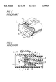
- FIG. 5 is a perspective view of a front portion of a front holder in a conventional connector
- FIG. 6 is a vertical sectional view of a connector having positive terminals in the conventional connector apparatus
- FIG. 7 is a vertical sectional view of another connector having positive terminals in another connector apparatus
- FIG. 8 is a perspective view of a front portion of the other modified front holder in the connector according to the present invention.
- FIG. 9 is a perspective view of a front portion of the other modified front holder in the connector according to the present invention.
- a connector apparatus is similar in construction to the conventional connector apparatus except for the front holder.
- a connector 1' includes a housing 2' made of injection-molded synthetic resin, waterproofing plugs 4' and a plurality of positive terminals 6' each connected to electrical wires.
- the housing 2' has a hood portion 2a' for protecting the positive terminals 6', in which a plurality of terminal receiving chambers 7' are bored therethrough, whereby the electrical joints 6a' of the plurality of positive terminals 6' can separately be fitted in the respective chambers 7'. Further, in the inner wall of each terminal receiving chamber 7', there is a lance 9' having a protrusion capable of mating with a recess 8' formed in the body of the positive terminal 6'.
- the waterproofing plug 4' attached to the wire is fitted into one terminal-insertion end portion of the housing 2' to hermetically seal each wire.
- a front holder 20 is inserted from the hood portion 2a' forming the front end portion of the housing 2' and the electrical joints 6a' of the positive terminals 6' are each passed through a plurality of holes 11' bored in a front wall portion. 10', whereas a plurality of spacers 12' extending from the front wall portion 10' are fitted into respective grooves 13' as deflection spaces of the lances 9' cut in a manner adjacent to the respective terminal receiving chambers 7' within the housing 2'.
- the deflection of the lance 9' is regulated by the spacer 12' fitted into the groove 13', and the lance 9' is completely fixed in such a state that it is kept engaging with the recess of the positive terminals 6'.
- the present invention features that the front holder 20 has an inserted guide piece 14' and a pull-out guide piece 22 extending inward and outward along the same axial line from the front wall portion 10' and that an opening 23 is bored in the front wall portion 10' along the axial line.
- the opening 23 has an open portion large enough to make the whole retaining head 17 pass therethrough and an adjoining pull-out portion 21 whose opening is slightly low so as to allow the engagement of the front wall portion 10' with the retaining head 17, whereby the opening 23 has a stepped upper edge.
- the front holder 20 may be arranged so that the retaining head 17 of the pullout tool 16 engaging with the pull-out portion 21 is completely surrounded by enlarging an internal space 24 sectioned with the rear portions 12a' of the spacers 12', the front wall portion 10' and the pull-out guide piece 22 by making the projected length of the pull-out guide piece 22 which is substantially equal to the projected length of the spacer 12'.
- the aforementioned front holder 20 of the connector apparatus is also applicable to a connector 30 equipped with a mat seal 31 and a mat seal cover 32 in place of the waterproofing plugs of the connector 1 shown in FIGS. 1 and 3.
- the front holder is not limited in shape to what has been defined in the aforementioned embodiment of the present invention but may be an engaging piece in direct engagement with a terminal instead of the spacer.
- the terminal fixing front holder 20 has the pull-out portion 21 and the pull-out guide portion 22 extending inward from the front wall portion 10', whereas the opening 23 for use in inserting the jig is bored in the front wall portion 10', whereby the whole front holder 20 is smoothly guided and pulled out by the pull-out portion 21 and the pull-out guide portion 22 via the front wall portion 10' in parallel to the inner wall face of the hood portion 2a' of the housing 2'. It is thus possible to effectively suppress the inner wall face of the hood portion 2a' from being damagingly scratched against the coupling operation of the connector.
- the pull-out portion 21 is formed between the front wall portion 10' and the rear portion 12a' of the spacer portion 12' extending inward from the front wall portion 10' along the same axial line as that of the pull-out guide portion 22, it is ensured that the retaining head 17 of the pull-out tool 16 engages with the pull-out portion 21 without touching the inner wall face of the hood portion 2a'.
- the connector apparatus since the internal space 24 sectioned with the spacer portion 12', the front wall portion 10' and the pull-out guide portion 22 is completely surrounded therewith in such a condition that the retaining head 17 of the pullout tool 16 is pulled out, the inner wall face of the hood portion 2a' can be suppressed from being scratched thereby while the pull-out tool 16 is inserted and pulled out.
- the pull-out guide portion 22 is extended up to substantially the same length of the spaces portion 12', the internal space surrounding the retaining head 17 of the pull-out tool 16 is enlarged and the parallel guide function of the extended pull-out guide piece 22 is increased, whereby the inner wall face of the hood portion 2a' is effectively suppressed from being scratched by the retaining head 17. Moreover, the front holder is never unsmoothly pulled out when it is pulled out as it is prevented from tilting in the hood portion.
- a groove 35 for use in inserting the pull-out tool 16 may be extended in the surfaces of the inserted guide piece 14" and the pull-out guide piece 22 to effect modification in that the height of the upper edge of the opening 23 is uniformized.
- an opening 23' for allowing the insertion of the pull-out tool 16 may be bored in a front wall portion 10" to effect modification in that the height of the upper edge of the opening 23' is uniformized.
- the pull-out tool 16 can engage with a rear surface of the front wall portion 10" about the opening 23' as indicated by arrow A.
Landscapes
- Connector Housings Or Holding Contact Members (AREA)
- Manufacturing Of Electrical Connectors (AREA)
Applications Claiming Priority (2)
| Application Number | Priority Date | Filing Date | Title |
|---|---|---|---|
| JP7-261625 | 1995-10-09 | ||
| JP26162595A JP3188384B2 (ja) | 1995-10-09 | 1995-10-09 | コネクタ装置 |
Publications (1)
| Publication Number | Publication Date |
|---|---|
| US5730626A true US5730626A (en) | 1998-03-24 |
Family
ID=17364498
Family Applications (1)
| Application Number | Title | Priority Date | Filing Date |
|---|---|---|---|
| US08/727,217 Expired - Lifetime US5730626A (en) | 1995-10-09 | 1996-10-08 | Connector apparatus |
Country Status (5)
| Country | Link |
|---|---|
| US (1) | US5730626A (fr) |
| EP (1) | EP0768732B1 (fr) |
| JP (1) | JP3188384B2 (fr) |
| DE (1) | DE69611499T2 (fr) |
| ES (1) | ES2154771T3 (fr) |
Cited By (14)
| Publication number | Priority date | Publication date | Assignee | Title |
|---|---|---|---|---|
| US5913697A (en) * | 1996-12-10 | 1999-06-22 | The Whitaker Corporation | Electrical connector having a secondary lock |
| US5944558A (en) * | 1997-05-08 | 1999-08-31 | Yazaki Corporation | Connector with projected rib to guide the holder and the jig to control the connectivity of the terminal |
| US6048225A (en) * | 1996-03-29 | 2000-04-11 | Framatome Connectors International | Connection module incorporating detachable contacts and connection block using said module |
| US6048226A (en) * | 1997-09-09 | 2000-04-11 | Yazaki Corporation | Front holder-incorporating connector |
| US6316951B1 (en) * | 1997-07-31 | 2001-11-13 | Sumitomo Wiring Systems, Ltd. | Inspection unit of a connector inspection apparatus |
| US6364705B1 (en) * | 1999-07-26 | 2002-04-02 | Tyco Electronics Logistics Ag | Connector including a releasable contact engaging latch |
| US6685506B1 (en) * | 2001-08-03 | 2004-02-03 | Sumitomo Wiring Systems, Ltd. | Connector and a method for connecting such connector with a mating connector |
| US20050250385A1 (en) * | 2004-05-07 | 2005-11-10 | Sumitomo Wiring Systems, Ltd. | Connector and a method of disassembling it |
| US20060141862A1 (en) * | 2002-09-25 | 2006-06-29 | Ryosei Electro-Circuit Systems, Ltd. | Electrical connector |
| US20110237098A1 (en) * | 2008-12-18 | 2011-09-29 | Shigeru Tajima | Plug, plug receptacle and electric power supplying system |
| CN102365793A (zh) * | 2009-03-24 | 2012-02-29 | Kum株式会社 | 母连接器组装件 |
| US20130230999A1 (en) * | 2010-11-12 | 2013-09-05 | Yazaki Corporation | Holder lock structure |
| KR101512852B1 (ko) | 2008-12-26 | 2015-04-16 | 주식회사 모아텍 | 커넥터의 이탈방지 구조체 |
| US20190356075A1 (en) * | 2018-05-18 | 2019-11-21 | Yazaki North America, Inc. | Electrical connector assembly with plug and cavity assembly and method of ultrasonically welding |
Families Citing this family (3)
| Publication number | Priority date | Publication date | Assignee | Title |
|---|---|---|---|---|
| EP0994310A1 (fr) | 1998-10-16 | 2000-04-19 | Polygo Holding GmbH | Rail pour support de tuyaux |
| JP2001351717A (ja) * | 2000-06-08 | 2001-12-21 | Sumitomo Wiring Syst Ltd | コネクタ |
| JP2004014271A (ja) * | 2002-06-06 | 2004-01-15 | Sumitomo Wiring Syst Ltd | リテーナを備えたコネクタ、およびリテーナ取り外し用治具 |
Citations (4)
| Publication number | Priority date | Publication date | Assignee | Title |
|---|---|---|---|---|
| US4797116A (en) * | 1987-01-26 | 1989-01-10 | Amp Incorporated | Electrical connector having a movable contact guide and lance-maintaining member |
| US5071369A (en) * | 1990-12-05 | 1991-12-10 | Amp Incorporated | Electrical connector having a terminal position assurance member |
| US5211582A (en) * | 1992-03-09 | 1993-05-18 | Amphenol Corporation | Repairable connector |
| US5529515A (en) * | 1993-08-06 | 1996-06-25 | Yazaki Corporation | Connector equipped with front member |
Family Cites Families (1)
| Publication number | Priority date | Publication date | Assignee | Title |
|---|---|---|---|---|
| JP2747501B2 (ja) * | 1993-06-08 | 1998-05-06 | 矢崎総業株式会社 | ハウジングホルダ内におけるハウジングブロックの係止解除具 |
-
1995
- 1995-10-09 JP JP26162595A patent/JP3188384B2/ja not_active Expired - Fee Related
-
1996
- 1996-10-08 EP EP96116110A patent/EP0768732B1/fr not_active Expired - Lifetime
- 1996-10-08 ES ES96116110T patent/ES2154771T3/es not_active Expired - Lifetime
- 1996-10-08 US US08/727,217 patent/US5730626A/en not_active Expired - Lifetime
- 1996-10-08 DE DE69611499T patent/DE69611499T2/de not_active Expired - Lifetime
Patent Citations (4)
| Publication number | Priority date | Publication date | Assignee | Title |
|---|---|---|---|---|
| US4797116A (en) * | 1987-01-26 | 1989-01-10 | Amp Incorporated | Electrical connector having a movable contact guide and lance-maintaining member |
| US5071369A (en) * | 1990-12-05 | 1991-12-10 | Amp Incorporated | Electrical connector having a terminal position assurance member |
| US5211582A (en) * | 1992-03-09 | 1993-05-18 | Amphenol Corporation | Repairable connector |
| US5529515A (en) * | 1993-08-06 | 1996-06-25 | Yazaki Corporation | Connector equipped with front member |
Cited By (21)
| Publication number | Priority date | Publication date | Assignee | Title |
|---|---|---|---|---|
| US6048225A (en) * | 1996-03-29 | 2000-04-11 | Framatome Connectors International | Connection module incorporating detachable contacts and connection block using said module |
| US5913697A (en) * | 1996-12-10 | 1999-06-22 | The Whitaker Corporation | Electrical connector having a secondary lock |
| US5944558A (en) * | 1997-05-08 | 1999-08-31 | Yazaki Corporation | Connector with projected rib to guide the holder and the jig to control the connectivity of the terminal |
| US6316951B1 (en) * | 1997-07-31 | 2001-11-13 | Sumitomo Wiring Systems, Ltd. | Inspection unit of a connector inspection apparatus |
| US6048226A (en) * | 1997-09-09 | 2000-04-11 | Yazaki Corporation | Front holder-incorporating connector |
| US6364705B1 (en) * | 1999-07-26 | 2002-04-02 | Tyco Electronics Logistics Ag | Connector including a releasable contact engaging latch |
| US6685506B1 (en) * | 2001-08-03 | 2004-02-03 | Sumitomo Wiring Systems, Ltd. | Connector and a method for connecting such connector with a mating connector |
| US7207841B2 (en) * | 2002-09-25 | 2007-04-24 | Mitsubishi Cable Industries, Ltd. | Electrical connector |
| US20060141862A1 (en) * | 2002-09-25 | 2006-06-29 | Ryosei Electro-Circuit Systems, Ltd. | Electrical connector |
| US7097503B2 (en) | 2004-05-07 | 2006-08-29 | Sumitomo Wiring Systems, Ltd. | Connector and a method of disassembling it |
| US20050250385A1 (en) * | 2004-05-07 | 2005-11-10 | Sumitomo Wiring Systems, Ltd. | Connector and a method of disassembling it |
| US8702435B2 (en) * | 2008-12-18 | 2014-04-22 | Sony Corporation | Plug, plug receptacle and electric power supplying system |
| US20110237098A1 (en) * | 2008-12-18 | 2011-09-29 | Shigeru Tajima | Plug, plug receptacle and electric power supplying system |
| KR101512852B1 (ko) | 2008-12-26 | 2015-04-16 | 주식회사 모아텍 | 커넥터의 이탈방지 구조체 |
| CN102365793B (zh) * | 2009-03-24 | 2013-11-20 | Kum株式会社 | 母连接器组装件 |
| CN102365793A (zh) * | 2009-03-24 | 2012-02-29 | Kum株式会社 | 母连接器组装件 |
| US20130230999A1 (en) * | 2010-11-12 | 2013-09-05 | Yazaki Corporation | Holder lock structure |
| US8926364B2 (en) * | 2010-11-12 | 2015-01-06 | Yazaki Corporation | Holder lock structure |
| US20190356075A1 (en) * | 2018-05-18 | 2019-11-21 | Yazaki North America, Inc. | Electrical connector assembly with plug and cavity assembly and method of ultrasonically welding |
| US11283211B2 (en) * | 2018-05-18 | 2022-03-22 | Yazaki North America, Inc. | Electrical connector assembly with plug and cavity assembly and method of ultrasonically welding |
| US11962107B2 (en) | 2018-05-18 | 2024-04-16 | Yazaki North America, Inc. | Electrical connector assembly with plug and cavity assembly and method of ultrasonically welding |
Also Published As
| Publication number | Publication date |
|---|---|
| EP0768732B1 (fr) | 2001-01-10 |
| ES2154771T3 (es) | 2001-04-16 |
| EP0768732A3 (fr) | 1997-05-21 |
| DE69611499D1 (de) | 2001-02-15 |
| EP0768732A2 (fr) | 1997-04-16 |
| JPH09106846A (ja) | 1997-04-22 |
| JP3188384B2 (ja) | 2001-07-16 |
| DE69611499T2 (de) | 2001-05-03 |
Similar Documents
| Publication | Publication Date | Title |
|---|---|---|
| EP0768732B1 (fr) | Boítier pour connecteur avec capuchon | |
| US4936795A (en) | Electrical connector | |
| US6364699B1 (en) | Cable connector assembly device with improved latching means | |
| US4990103A (en) | Plug with cord | |
| US5993268A (en) | Electrical connector with terminal retaining means | |
| EP0644619A2 (fr) | Méthode et appareil pour verrouillage double d'un terminal dans un connecteur | |
| US12512627B2 (en) | Shield connector | |
| US5957715A (en) | Waterproof connector | |
| EP1100156B1 (fr) | Connecteur et son assemblage | |
| EP0732771A2 (fr) | Connecteur | |
| US11081835B2 (en) | Connector | |
| US6165012A (en) | Press-connecting connector | |
| US5482476A (en) | Panel-mounted electrical connector | |
| US5123866A (en) | Electrical connector with terminal retaining member | |
| US5980332A (en) | Electrical connector | |
| US5931707A (en) | Connector with terminal hooking device | |
| US6341985B2 (en) | Connector unit having front holder | |
| US5984737A (en) | Structure of connector housing | |
| JP2000260519A (ja) | 雄型コネクタ | |
| US6042428A (en) | Connector insert retention | |
| US6227910B1 (en) | EMI shield | |
| US6183313B1 (en) | Double lock connector | |
| US7086899B1 (en) | Waterproof connector | |
| JP3097825B2 (ja) | コネクタ装置 | |
| KR100395021B1 (ko) | 모듈러 잭 |
Legal Events
| Date | Code | Title | Description |
|---|---|---|---|
| AS | Assignment |
Owner name: YAZAKI CORPORATION, JAPAN Free format text: ASSIGNMENT OF ASSIGNORS INTEREST;ASSIGNORS:TOMITA, YOSHINORI;SUZUKI, NAOMI;REEL/FRAME:008264/0921 Effective date: 19961001 |
|
| STCF | Information on status: patent grant |
Free format text: PATENTED CASE |
|
| FEPP | Fee payment procedure |
Free format text: PAYOR NUMBER ASSIGNED (ORIGINAL EVENT CODE: ASPN); ENTITY STATUS OF PATENT OWNER: LARGE ENTITY |
|
| CC | Certificate of correction | ||
| FPAY | Fee payment |
Year of fee payment: 4 |
|
| FPAY | Fee payment |
Year of fee payment: 8 |
|
| FPAY | Fee payment |
Year of fee payment: 12 |