US574032A - Mud-guard for bicycles - Google Patents
Mud-guard for bicycles Download PDFInfo
- Publication number
- US574032A US574032A US574032DA US574032A US 574032 A US574032 A US 574032A US 574032D A US574032D A US 574032DA US 574032 A US574032 A US 574032A
- Authority
- US
- United States
- Prior art keywords
- guard
- arm
- reel
- mud
- arms
- Prior art date
- Legal status (The legal status is an assumption and is not a legal conclusion. Google has not performed a legal analysis and makes no representation as to the accuracy of the status listed.)
- Expired - Lifetime
Links
- 238000010276 construction Methods 0.000 description 4
- 230000000153 supplemental effect Effects 0.000 description 2
- 241001351439 Oneida Species 0.000 description 1
- 210000005069 ears Anatomy 0.000 description 1
Images
Classifications
-
- B—PERFORMING OPERATIONS; TRANSPORTING
- B62—LAND VEHICLES FOR TRAVELLING OTHERWISE THAN ON RAILS
- B62J—CYCLE SADDLES OR SEATS; AUXILIARY DEVICES OR ACCESSORIES SPECIALLY ADAPTED TO CYCLES AND NOT OTHERWISE PROVIDED FOR, e.g. ARTICLE CARRIERS OR CYCLE PROTECTORS
- B62J15/00—Mud-guards for wheels
Definitions
- My invention relates to improvements in folded mud-guards for bicycles.
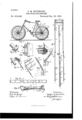
- Figure 1 shows a bicycle with my folding m ud-guard applied.
- Fig. 2 shows particularly a hook and ferrule used in securing the front end of the guard in connection with a section of the frame.
- Fig. 3 shows one of the attachments used in the construction for attaching the guard to the frame.
- Fig. 4 shows in side elevation the two arms for carrying the guard as the parts appear when in folded position, the guard being removed from the parts.
- Fig. 5 shows in side elevation one of the pair of swinging arms for carrying the end of the guard.
- Fig. 6 shows in perspective details of the upper end of the arm and the eccentric reel for the ilexible guard.
- FIG. 7 shows a slightly-modied form of construction of the lower end of the arms which carry the rear end of the guard in connection with the forked pivotal piece by means of which it is attached to the machine.
- Fig. 8 shows the same parts shown in Fig. 7 in the posit-ion which they assume when the guard is held extended.
- Fig. 9 shows details, mostly in section, of the manner of clamping the removable ears on which the swinging arms for carrying the rear end of the guard are pivoted.
- Fig. 10 shows the guard reeled.
- Fig. 11 shows the guard.
- Fig. 12 shows the guard in position preparatory to being reeled.
- 1 and 2 indicate frame-bars of an ordinary safety-bicycle, mounted on forward and rear wheels A and B in the usual manner.
- a iiexible mud-guard 3 consisting of three parts 3a, 3b, and 3", as shown in Figs. 1l and 12, with intermediate narrow connections, as shown at a b in the same iigures.
- the guard is also provided with several semilexible transverse ribs, as shown in dotted lines at c c.
- the guard I In the forward end of the guard I provide a transverse pin f1, with the guard cut ont on the middle portion of the pin, so that it can be placed upon the hook 5 of the clip G, secured upon the front frameebar 1.
- the fixture 7 On the frame-bars 2 2, adjacent to the seat, is clamped the fixture 7, which has a wire bracket having screw-threaded studs 8 S, extending between the bars 2, and on which is mounted the clamping-bar 9, and the device is held to the frame-bars 2 by the action of the clamping-nuts 10 10.
- To the fixture 7 is attached the narrow portion Z) of the guard.
- the rear end of the rear portion 3a of the guard is secured to the swinging side of the eccentric reel 1l, which reel is pivoted upon the crossbar 12, extending between the heads of the arms 13 13, which carry the rear end oi' the guard over the rear wheel.
- the bar 12 is preferably screw-threaded at each end with right and left hand threads, so that by turning it can be readily disengaged from the arms to allow the guard to be removed or applied, as desired.
- a sliding bar or reel-lock 14 On the arm 13 is mounted a sliding bar or reel-lock 14, adapted to become engaged with the reel 11, with the guard coiled or wound thereon, and prevent the same from unwinding.
- a pair of partially-split sleeves 15 15 Under the sliding bar 14 is provided a pair of partially-split sleeves 15 15, which assist in holding the bar 14 in position when in use, and the sleeves 15 are in turn held by a light spiral spring 16, confined between the sleeve and thebushing 17 on the arm.
- the arms 13, either of the form of construction shown in Fig. 4., 5, 7, or 8, are pivoted at 18 on a removable forked ear 19 straddling the rear axle 2O and clamped between the fork 21 on the rear end of the frame and the axlebearing piece 22 by the action of the arm 28.
- a sliding catch-rod 25 which slides in xed keepers 26 and 27, secured on the arm, and is held by a movable keeper 28, engaging the arm.
- the rod 25 also serves to strengthen the arm at the base.
- the lower end of the arm 25 is adapted to be projected when it is desired to have the mud-guard in extended position, so that it will engage the projecting pin or shoulder 29 in the removable ear 19.
- a light spiral spring 30 which is confined between the collar 31 and the keeper 27, and when the end of the bar is projected this spring is compressed, but the bar is held down by reason of the end binding on the pin 29.
- Above the end of the sliding bar 25 is introduced in the arm a convolution 32, which prevents the arm being kinked at the keeper 28 in case it is sprung or placed under too great tension in straining the guard in extended position.
- I also provide a supplemental piece S3, spanning the 'angle when the guard is extended between'the parts 3l and 3 at the fixture 7, and this supplemental piece passes close to the rim of the wheel and acts as a better guard than it would with the piece omitted.
- the forward end of the piece 3 is detached from the hook 5 and passed backward under the frame-bars to the reel 11 and through the loop of the reel and through a keeper 34, secured on the piece 3 in the double position shown in the drawings.
- the arms 13 are then swung slightly rearward to release the slidingbars 25 from the pins, which are moved upward and disengaged by the action of the spring 30, either independentlyT or with assistance,
- the locking-bar 14 of the upper end of the arms is slid down the same, so as to allow the reel to revolve around the shaft 12, when, by revolving it around the shaft, the guard is rolled onto the reel into the form shown in Fig. 10, when the catchbar is moved up to engage the proj ecting side of the eccentric reel with the guard wrapped thereon and secure itin folded position.
- the locking-bar is moved out of the way to disengage the reel, when the guard may be unwound and the arms swung rearward to their open position and secured by the sliding rods 25, as heretofore described.
- the portions 3l and Se of the guard are then unfolded and passed into their position and engaged upon the hook 5.
Landscapes
- Engineering & Computer Science (AREA)
- Mechanical Engineering (AREA)
- Emergency Lowering Means (AREA)
- Mechanical Means For Catching Fish (AREA)
- Axle Suspensions And Sidecars For Cycles (AREA)
Description
(No Model.)
C. M. HITCHCOCK.
MUD GUARD FOR BICYCLES.
Patented Deo. `29, 1896,
UNITED STATES ATENT OFFICE.
CHARLES M. HITCHCOCK, OF UTICA, NIJVV YORK.
MUD-GUARD FOR BICYCLES.
SPECIFICATION forming part of Letters Patent No. 574,032, dated December 29, 1896. Application filed October 14, 1893. Serial No. I188,117. (No model.)
To colt whom, it may concern:
Be it known that I, CHARLES M. HITCH- COCK, of Utica, in the county of Oneida and State of New York, haveinvented certain new and useful Improvements in Mud-Guards for Bicycles; and I do hereby declare that the following is a full, clear, and exact description of the invention, which will enable others skilled in the art to which it appertains to make and use the saine, reference being had to the accompanying drawings, and to the letters and figures of reference marked thereon, which form part of this speciiication.
My invention relates to improvements in folded mud-guards for bicycles.
In the drawings which accompany and form a part of this specification, Figure 1 shows a bicycle with my folding m ud-guard applied. Fig. 2 shows particularly a hook and ferrule used in securing the front end of the guard in connection with a section of the frame. Fig. 3 shows one of the attachments used in the construction for attaching the guard to the frame. Fig. 4 shows in side elevation the two arms for carrying the guard as the parts appear when in folded position, the guard being removed from the parts. Fig. 5 shows in side elevation one of the pair of swinging arms for carrying the end of the guard. Fig. 6 shows in perspective details of the upper end of the arm and the eccentric reel for the ilexible guard. Fig. 7 shows a slightly-modied form of construction of the lower end of the arms which carry the rear end of the guard in connection with the forked pivotal piece by means of which it is attached to the machine. Fig. 8 shows the same parts shown in Fig. 7 in the posit-ion which they assume when the guard is held extended. Fig. 9 shows details, mostly in section, of the manner of clamping the removable ears on which the swinging arms for carrying the rear end of the guard are pivoted. Fig. 10 shows the guard reeled. Fig. 11 shows the guard. Fig. 12 shows the guard in position preparatory to being reeled.
Referring to the reference letters and figures in a more specific description, 1 and 2 indicate frame-bars of an ordinary safety-bicycle, mounted on forward and rear wheels A and B in the usual manner. In connection with the wheel I provide a iiexible mud-guard 3, consisting of three parts 3a, 3b, and 3", as shown in Figs. 1l and 12, with intermediate narrow connections, as shown at a b in the same iigures. The guard is also provided with several semilexible transverse ribs, as shown in dotted lines at c c.
In the forward end of the guard I provide a transverse pin f1, with the guard cut ont on the middle portion of the pin, so that it can be placed upon the hook 5 of the clip G, secured upon the front frameebar 1. On the frame-bars 2 2, adjacent to the seat, is clamped the fixture 7, which has a wire bracket having screw-threaded studs 8 S, extending between the bars 2, and on which is mounted the clamping-bar 9, and the device is held to the frame-bars 2 by the action of the clamping-nuts 10 10. To the fixture 7 is attached the narrow portion Z) of the guard. The rear end of the rear portion 3a of the guard is secured to the swinging side of the eccentric reel 1l, which reel is pivoted upon the crossbar 12, extending between the heads of the arms 13 13, which carry the rear end oi' the guard over the rear wheel. The bar 12 is preferably screw-threaded at each end with right and left hand threads, so that by turning it can be readily disengaged from the arms to allow the guard to be removed or applied, as desired.
On the arm 13 is mounted a sliding bar or reel-lock 14, adapted to become engaged with the reel 11, with the guard coiled or wound thereon, and prevent the same from unwinding. Under the sliding bar 14 is provided a pair of partially-split sleeves 15 15, which assist in holding the bar 14 in position when in use, and the sleeves 15 are in turn held by a light spiral spring 16, confined between the sleeve and thebushing 17 on the arm. The arms 13, either of the form of construction shown in Fig. 4., 5, 7, or 8, are pivoted at 18 on a removable forked ear 19 straddling the rear axle 2O and clamped between the fork 21 on the rear end of the frame and the axlebearing piece 22 by the action of the arm 28.
On the lower end of the arm 13 is provided a sliding catch-rod 25, which slides in xed keepers 26 and 27, secured on the arm, and is held bya movable keeper 28, engaging the arm. The rod 25 also serves to strengthen the arm at the base.
IOO
The lower end of the arm 25 is adapted to be projected when it is desired to have the mud-guard in extended position, so that it will engage the projecting pin or shoulder 29 in the removable ear 19. On the arm or bar 25 is provided a light spiral spring 30, which is confined between the collar 31 and the keeper 27, and when the end of the bar is projected this spring is compressed, but the bar is held down by reason of the end binding on the pin 29. Above the end of the sliding bar 25 is introduced in the arm a convolution 32, which prevents the arm being kinked at the keeper 28 in case it is sprung or placed under too great tension in straining the guard in extended position.
In the guard, as shown in Figs. 1 and 12, I also provide a supplemental piece S3, spanning the 'angle when the guard is extended between'the parts 3l and 3 at the fixture 7, and this supplemental piece passes close to the rim of the wheel and acts as a better guard than it would with the piece omitted.
To fold or reel the guard from the position shown in Fig. 1, the forward end of the piece 3 is detached from the hook 5 and passed backward under the frame-bars to the reel 11 and through the loop of the reel and through a keeper 34, secured on the piece 3 in the double position shown in the drawings. The arms 13 are then swung slightly rearward to release the slidingbars 25 from the pins, which are moved upward and disengaged by the action of the spring 30, either independentlyT or with assistance, The locking-bar 14 of the upper end of the arms is slid down the same, so as to allow the reel to revolve around the shaft 12, when, by revolving it around the shaft, the guard is rolled onto the reel into the form shown in Fig. 10, when the catchbar is moved up to engage the proj ecting side of the eccentric reel with the guard wrapped thereon and secure itin folded position. To
extend the guard, the locking-bar is moved out of the way to disengage the reel, when the guard may be unwound and the arms swung rearward to their open position and secured by the sliding rods 25, as heretofore described. The portions 3l and Se of the guard are then unfolded and passed into their position and engaged upon the hook 5.
In the modified form of construction sh own in Figs. 8 and 9 the upper portion of the sliding bar, as indicated at 25, is shortened, so as to bring the clips or keepers 2G.and 2S:L together when the end of the bar is projected, as heretofore described.
Vhat I claim as new, and desire to secure by Lett-ers Patent, is-
1. The combination with a bicycle of a flexible mud-guard, a reel on which the guard is adapted to be wound, pivoted eccentrically and the locking device for the reel, substantially as set forth.
2. The combination in a bicycle of the fiexible 1nud-guard, a radial arm for holding the guard extended over the wheel pivoted adjacent to the center of the wheel, a sliding bar mounted on the pivotal end of the arm and the projection on the frame with which the bar is adapted to engage to hold the guard extended, substantially7 as set forth.
3. The combination with a bicycle of a flexible mud-guard, means for attaching one end to the frame, a pair of guard-holdin g arms, a guard-reel to which the other end of the guard is attached mounted eccentricallyin the projecting ends of the arms, a locking means for securing the reel with the guard wound thereon engaging with the extended side of the eccentric reel, substantially as set forth.
et. The combination with a bicycle of the flexible mudnguard, holding-arms, an armhanger to which the arm is pivoted, having a iixed locking-shoulder and adapted to be secured to the frame, the sliding catch on the arm adapted to engage the shoulder when the guard is fully extended, and hold the arm and guard extended,substantially as set forth.
In witness wheref I have affixed my signature in presence of two witnesses.
CHARLES M. HITCHCOCK.
Vitnesses:
J. II. BRoWN, GEO. A. CHAPIN.
Publications (1)
| Publication Number | Publication Date |
|---|---|
| US574032A true US574032A (en) | 1896-12-29 |
Family
ID=2642727
Family Applications (1)
| Application Number | Title | Priority Date | Filing Date |
|---|---|---|---|
| US574032D Expired - Lifetime US574032A (en) | Mud-guard for bicycles |
Country Status (1)
| Country | Link |
|---|---|
| US (1) | US574032A (en) |
-
0
- US US574032D patent/US574032A/en not_active Expired - Lifetime
Similar Documents
| Publication | Publication Date | Title |
|---|---|---|
| US4022485A (en) | Collapsible bicycle | |
| US576769A (en) | Liams | |
| US574032A (en) | Mud-guard for bicycles | |
| US2711328A (en) | Folding baby stroller | |
| US453094A (en) | Island | |
| US558377A (en) | Adam f | |
| US653681A (en) | Combined bicycle prop and lock. | |
| US544935A (en) | shone | |
| US645145A (en) | Folding bicycle. | |
| US1226323A (en) | Bicycle mud-guard. | |
| US636155A (en) | Device for coupling bicycles. | |
| US606359A (en) | Half to james mccormick | |
| US520245A (en) | Bicycle mud-guard | |
| US398945A (en) | Luggage-carrier for bicycles | |
| US598083A (en) | Bicycle | |
| US1254858A (en) | Top for bicycles and motor-cycles. | |
| US1060649A (en) | Support and lock for cycles. | |
| US1188105A (en) | Wind-shield for motor-cycles. | |
| US253211A (en) | Carrier attachment for bicycles | |
| US549792A (en) | Handle-bar attachment | |
| US594991A (en) | Bicycle | |
| US511232A (en) | Wire stringer and stretcher | |
| US506600A (en) | Bicycle-support | |
| US575453A (en) | Charles l | |
| US685424A (en) | Luggage-carrier for bicycles. |