US5746357A - Plunger and apparatus useful in extruding or dispensing viscous materials - Google Patents
Plunger and apparatus useful in extruding or dispensing viscous materials Download PDFInfo
- Publication number
- US5746357A US5746357A US08/635,984 US63598496A US5746357A US 5746357 A US5746357 A US 5746357A US 63598496 A US63598496 A US 63598496A US 5746357 A US5746357 A US 5746357A
- Authority
- US
- United States
- Prior art keywords
- disc
- plunger
- edge
- concave portion
- cylinder
- Prior art date
- Legal status (The legal status is an assumption and is not a legal conclusion. Google has not performed a legal analysis and makes no representation as to the accuracy of the status listed.)
- Expired - Fee Related
Links
- 239000011345 viscous material Substances 0.000 title claims abstract description 15
- 239000000463 material Substances 0.000 claims abstract description 37
- 239000012530 fluid Substances 0.000 claims description 7
- -1 polyethylene Polymers 0.000 claims description 6
- 239000004033 plastic Substances 0.000 claims description 5
- 229920003023 plastic Polymers 0.000 claims description 5
- 239000004698 Polyethylene Substances 0.000 claims description 3
- 229920000573 polyethylene Polymers 0.000 claims description 3
- 229920000915 polyvinyl chloride Polymers 0.000 claims description 3
- 239000004800 polyvinyl chloride Substances 0.000 claims description 3
- 239000012815 thermoplastic material Substances 0.000 claims description 3
- 239000004743 Polypropylene Substances 0.000 claims description 2
- 239000004793 Polystyrene Substances 0.000 claims description 2
- 229920001400 block copolymer Polymers 0.000 claims description 2
- 150000001993 dienes Chemical class 0.000 claims description 2
- 229920001155 polypropylene Polymers 0.000 claims description 2
- 229920002223 polystyrene Polymers 0.000 claims description 2
- PPBRXRYQALVLMV-UHFFFAOYSA-N Styrene Chemical compound C=CC1=CC=CC=C1 PPBRXRYQALVLMV-UHFFFAOYSA-N 0.000 claims 2
- 239000000203 mixture Substances 0.000 claims 1
- 239000000853 adhesive Substances 0.000 description 4
- 230000001070 adhesive effect Effects 0.000 description 4
- 229920001971 elastomer Polymers 0.000 description 3
- 238000001125 extrusion Methods 0.000 description 3
- 238000007789 sealing Methods 0.000 description 3
- 239000011521 glass Substances 0.000 description 2
- 239000002184 metal Substances 0.000 description 2
- 125000003118 aryl group Chemical group 0.000 description 1
- 230000000712 assembly Effects 0.000 description 1
- 238000000429 assembly Methods 0.000 description 1
- 239000011111 cardboard Substances 0.000 description 1
- 230000001419 dependent effect Effects 0.000 description 1
- 239000011346 highly viscous material Substances 0.000 description 1
- 239000000178 monomer Substances 0.000 description 1
- 229920000642 polymer Polymers 0.000 description 1
- 229920000098 polyolefin Polymers 0.000 description 1
- 238000003825 pressing Methods 0.000 description 1
- 229920000468 styrene butadiene styrene block copolymer Polymers 0.000 description 1
- 229940034610 toothpaste Drugs 0.000 description 1
- 239000000606 toothpaste Substances 0.000 description 1
- 239000002023 wood Substances 0.000 description 1
Images

Classifications
-
- B—PERFORMING OPERATIONS; TRANSPORTING
- B65—CONVEYING; PACKING; STORING; HANDLING THIN OR FILAMENTARY MATERIAL
- B65D—CONTAINERS FOR STORAGE OR TRANSPORT OF ARTICLES OR MATERIALS, e.g. BAGS, BARRELS, BOTTLES, BOXES, CANS, CARTONS, CRATES, DRUMS, JARS, TANKS, HOPPERS, FORWARDING CONTAINERS; ACCESSORIES, CLOSURES, OR FITTINGS THEREFOR; PACKAGING ELEMENTS; PACKAGES
- B65D83/00—Containers or packages with special means for dispensing contents
- B65D83/76—Containers or packages with special means for dispensing contents for dispensing fluent contents by means of a piston
Definitions
- the invention relates to a plunger, and dispensing device incorporating the plunger, useful in dispensing viscous materials, for instance, adhesive materials.
- Dispensing devices for dispensing or extruding viscous material generally comprise a cylindrical container having a nozzle or port which has a cross-sectional area which is significantly less then the cross-sectional area of the cylindrical container.
- the material to be dispensed is placed in the container and a plunger or piston is placed on the opposite end of the material to be dispensed from the port or nozzle. Pressure is applied by means of the plunger piston to the viscous material, thereby forcing a portion of the viscous material out of the nozzle or port and allowing its application in an appropriate manner.
- U.S. Pat. No. 4,907,727 discloses a device having improved plunger assemblies. Disclosed is a dispensing device and plunger designed to prevent this loss of sealing.
- the plunger assembly uses a plastic end-cap which can deform when pressure is applied. Internal to the end-cap is a piston having on its head, a rubber pad which fits inside of the end-cap. This rubber disc reacts to applied forces by expanding radially to tighten the seal of the end-cap so as to prevent leaking through the rear. The rubber disc and the end-cap form an air chamber which resists deformation. This is a complex solution which is costly to the user.
- the invention is a plunger useful in extruding or dispensing viscous material, which comprises a thin disc of a material which is capable of deforming when subjected to back pressure during use.
- the edge of the disc has a circular shape and a cylindrical lip attached to the edge of the disc, which lip is disposed perpendicular to the edge of the disc.
- the disc has a face and a back surface located on opposite sides of the sheet. This also has a symmetrical convex portion which protrudes beyond the plane defined by the edge of the disc in the direction of the face and a peak of the convex portion disposed in the center of the disc. This further comprises a symmetrical concave portion which protrudes beyond the plane defined by the edge of the disc in the direction of the back surface.
- the concave portion of the disc surrounds the convex portion of the disc and the convex portion starts at the bottom of the concave portion.
- the radius of the convex portion measured from the peak to the bottom of the concave portion is sufficient to withstand the back pressure exerted during use without inverting.
- the slope of the wall of the concave portion from the edge to the bottom of the concave portion is disposed such that, when back pressure is exerted on the plunger, the edge deforms radially outward.
- the invention is a plunger, as described above, fabricated from a rigid, deformable plastic.
- the plunger disclosed herein is capable of working in any commercially available system while allowing the extrusion of viscous material without the loss through the back of the cylindrical container in which the material is extruded.
- the plunger is incorporated into an apparatus which meets the object of the invention. Further, the plunger allows extrusion of materials under conditions which create back pressure of up to 450 psi.
- FIG. 1 is a side view of the plunger of the invention.
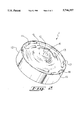
- FIG. 2 is an off-set view of the plunger illustrating the circular face and the lip of the plunger.
- FIG. 3 is an illustration of the plunger in a dispensing apparatus.
- FIG. 1 is a cut-away view of a plunger (1) according to the invention wherein the cut is taken through the center of the plunger and the view is from the side.
- FIG. 1 demonstrates a plunger (1) comprising a circular shaped disc (10) having an edge (11) located around the periphery of the disc.
- the plunger (1) is a thin sheet of a material in the shape of a cylindrical disc (10). Protruding from the edge of the disc (11) and disposed perpendicular to the edge of the disc (11) is a cylindrical lip (12).
- the cylindrical lip (12) is adapted to stabilize the plunger (1) during use in a circular dispensing apparatus (not shown in FIG. 1).
- the disc (10) has a face (13) and a backside (14).
- the face (13) of the symmetrical disc (10) has a symmetrical convex portion (15).
- the peak (16) of the symmetrical convex portion (15) protrudes beyond the plane defined by the edge (11) of the disc in the direction of the face (13), and is disposed at the center of the disc.
- the disc (10) further has a symmetrical concave portion (17) which protrudes beyond the plane defined by the edge (11) of the disc (10) in the direction of the back surface (14) wherein the concave portion (17) surrounds the convex portion (15).
- the convex portion (15) starts at the bottom (18) of the concave portion (17) of the disc (10).
- the radius of the concave portion (15) is measured from the peak (16) to the bottom (18) of the concave portion (17).
- the slope (19) of the concave portion (17) of the disc (10) from the edge (11) of the disc (10) to the bottom (18) of the concave portion (17) of the disc (10) is selected such that, when back pressure is applied to the face (15) of the disc (10), the edge (11) of the disc (10) expands radially outward and forms a seal between the edge (11) of the disc (10) and the inside wall of a dispenser (not shown).
- FIG. 2 is an off-set view of the plunger of the invention showing the entire face and a portion of the lip of the invention.
- FIG. 2 demonstrates the plunger (1), a face (13) and its edge (11) located around the periphery of a circular shaped disc (10). Also shown is the cylindrical lip (12) protruding from the edge of the disc (10) and disposed perpendicular to the edge of the disc (11).
- the symmetrical convex portion (15) of the face (13) of the symmetrical disc (10) is shown.
- the peak (16) of the symmetrical convex portion (15) protrudes beyond the plane defined by the edge (11) of the disc in the direction of the face (13) and is disposed at the center of the disc (10).
- the symmetrical concave portion (17) which surrounds the convex portion (15) and has a bottom (18) is shown.
- the slope (19) of the concave portion (17) of the disc (10) from the edge (11) of the disc (10) to the bottom (18) of the concave portion (17) of the disc (10) is shown.
- FIG. 3 is a dispenser (20) which contains a plunger (1) as described hereinbefore.
- the dispenser comprises a circular cylinder (21) which is adapted for holding materials which exhibit fluid characteristics under pressure.
- the plunger (1) is disposed in the dispenser (20) such that the lip (12) lies adjacent to the wall of a circular dispenser (20) and the plane defined by the edge of the plunger (11) is perpendicular to the direction of the cylinder (21).
- At one end of the circular cylinder (21) is an end-piece (22) which has a port (23) adapted for removal of the materials from the end of the cylinder (21).
- the port (23) has a cross-sectional area less than that of the cylinder (21).
- the face (13) of the plunger is directed toward the closed end (22) having a port (23) in it.
- the plunger further contains a piston or mechanical ram (24) adapted to push the plunger (10) in the direction of the end-piece (22) having the port (23).
- a piston or mechanical ram (24) adapted to push the plunger (10) in the direction of the end-piece (22) having the port (23).
- material contained in the circular cylinder (21) is forced through the port (23) so that it may be dispensed as desired.
- the plunger may be made of any material which has an elastic modulus such that the material will deform when exposed to significant back pressure but is also capable of pushing the material to be extruded from the dispensing apparatus through the port in the end-piece.
- the material that the plunger is made from has a modulus of 75,000 psi or greater, and more preferably 100,000 psi or greater.
- the material from which the plunger is prepared has a modulus of 600,000 psi or less and more preferably 500,000 psi or less.
- the material from which the plunger is made must be such that it has the strength to withstand the back pressure exerted by the material contained in the cylinder during extrusion of the material out the port.
- the material withstands a back pressure of 50 psi or greater, more preferably 100 psi or greater, and most preferably 150 psi or greater.
- the material from which the plunger is prepared withstands a back pressure of 400 psi or less and more preferably 250 psi or less.
- the plunger is preferably prepared from a rigid thermoplastic material. More preferably, the rigid thermoplastic material is a polyolefin, vinylidene aromatic polymer, a monovinylidene aromatic monomer-conjugated diene block copolymer, or polyvinylchloride.
- the plunger is polystyrene, polyethylene, polypropylene, polyvinylchloride, or a styrene-butadiene-styrene block copolymer. Even more preferably, the plunger is made from polyethylene.
- the thickness of the plunger should be sufficient to withstand the back pressures described hereinbefore.
- the plunger has a thickness of 0.50 mm or greater, more preferably 1.25 mm or greater and most preferably 1.75 mm or greater.
- the plunger has a thickness of 7.50 mm or less, more preferably 5.00 mm or less and most preferably 3.00 mm or less.
- the plunger preferably has a diameter, as measured along the face from edge to edge at its thickest point, which is slightly less than the inside diameter of the dispenser.
- the diameter should be such that the plunger can be inserted into the cylinder yet large enough such that when the plunger is subjected to back pressure, it deforms radially to form a seal between the edge of the plunger and the circular cylinder. It is advantageous that there be a small air gap between the edge of the plunger and the cylinder wall to allow air to flow past the plunger as it is inserted into or removed from the dispensing apparatus.
- the diameter of the plunger is 12.5 mm or greater, more preferably 25 mm or greater and most preferably 38 mm or greater.
- the diameter of the plunger is 127 mm or less more preferably 100 mm or less and most preferably 75 mm or less.
- the lip of the plunger in use is adjacent to the wall of the cylinder and is long enough to provide stability to the plunger and to prevent misalignment.
- the lip should be long enough to prevent cocking and binding of the plunger during use when back pressure is applied to the face of the plunger.
- the lip has a length of 5 mm or greater, and more preferably 15 mm or greater.
- the lip has a length of 50 mm or less and more preferably 40 mm or less.
- the convex portion of the face protrudes in the face direction from the plane defined by the edge of the disc.
- the distance that it protrudes from such plane is dependent upon the diameter of the disc and the back pressure which the plunger is designed to withstand.
- the distance ratio of protrusion to the diameter from the edge plane of the edge of the disc to the peak of the convex portion is 0.1 or greater, more preferably 0.13 or greater, and is preferably 0.4 or less and more preferably 0.25 or less.
- the radius of the convex portion of the disc, as measured from the peak to the bottom of the concave portion of the disc, is sufficient such that when the plunger is exposed to back pressure as described herein, the convex portion does not invert.
- the concave portion of the disc is symmetrical and surrounds the convex portion.
- the concave portion protrudes in the direction of the back surface and the bottom of the convex portion provides an edge on the back surface of the disc such that the means for applying pressure such as a piston can rest against the plunger and thereby force the plunger forward toward the end-piece on the cylinder which houses the plunger.
- the convex portion starts at the bottom of the concave portion.
- the slope of the wall of the concave portion, from the edge of the disc to the bottom of the concave portion, should be such that when back pressure is applied to the plunger, the plunger deforms radially and such deformation forms a seal between the edge of the plunger and the cylinder wall such that the material to be dispensed or extruded does not leak behind the plunger.
- the slope of the outer wall of the concave portion is at an angle of 10 degrees or greater, more preferably 20 degrees or greater, even more preferably 25 degrees or greater and most preferably 40 degrees or greater.
- the slope of the outer wall of the concave portion is at an angle of 90 degrees or less, more preferably 80 degrees or less, even more preferably 70 degrees or less and most preferably 50 degrees or less.
- the angle is measured from the plane defined by the edge of the plunger.
- the plunger of the invention can be used in any conventional apparatus which is useful in extruding or dispensing viscous materials.
- a preferred apparatus is illustrated in FIG. 3.
- the plunger can be used in any commercially available apparatus.
- the cylinder itself can be plastic, metal or cardboard.
- the cylinder has one end closed with a port in it designed for extruding or dispensing material.
- the port has a cross-section which is less than the cross-section of the cylinder.
- This port can be a hole or a nozzle or any other means for allowing material to escape from the cylinder when exposed to pressure.
- the apparatus further contains a means for exerting pressure on the back surface of the plunger. This means should exert sufficient pressure to extrude the material contained in the cylinder through the port.
- the means for exerting pressure can be any means for exerting pressure well known to those skilled in the art of dispensing apparatus wherein this dispensing apparatus is designed to extrude or dispense viscous materials.
- the pressure applied to the back surface of the plunger may be applied by mechanical means such as a piston, driven by electrical means, hydraulic means or by the application of air.
- the piston can rest on the backside of the concave portion.
- pressure can be placed on the backside of the pistons by use of high pressure air or hydraulic pressure. In this embodiment, care should be taken such that the seal between the edge or lip of the plunger is not broken.
- the apparatus of the invention is useful for extruding material which is fluid under pressure. Such materials are, for example, toothpaste, adhesive, foodstuff, etc.
- the material has a viscosity of about 50,000 centipoise or greater and more preferably about 100,000 centipoise or greater.
- the material dispensed or extruded by the apparatus under the invention has a viscosity of about 2,000,000 centipoise or less and more preferably 1,000,000 centipoise or less.
- the material can be extruded onto a variety of surfaces to be bonded together, such as glass, metal or wood or plastic.
Landscapes
- Engineering & Computer Science (AREA)
- Mechanical Engineering (AREA)
- Coating Apparatus (AREA)
- Containers And Packaging Bodies Having A Special Means To Remove Contents (AREA)
Priority Applications (2)
| Application Number | Priority Date | Filing Date | Title |
|---|---|---|---|
| US08/635,984 US5746357A (en) | 1996-04-22 | 1996-04-22 | Plunger and apparatus useful in extruding or dispensing viscous materials |
| CA002203203A CA2203203C (fr) | 1996-04-22 | 1997-04-21 | Piston plongeur et appareil servant a extruder et distribuer des materiaux visqueux |
Applications Claiming Priority (1)
| Application Number | Priority Date | Filing Date | Title |
|---|---|---|---|
| US08/635,984 US5746357A (en) | 1996-04-22 | 1996-04-22 | Plunger and apparatus useful in extruding or dispensing viscous materials |
Publications (1)
| Publication Number | Publication Date |
|---|---|
| US5746357A true US5746357A (en) | 1998-05-05 |
Family
ID=24549915
Family Applications (1)
| Application Number | Title | Priority Date | Filing Date |
|---|---|---|---|
| US08/635,984 Expired - Fee Related US5746357A (en) | 1996-04-22 | 1996-04-22 | Plunger and apparatus useful in extruding or dispensing viscous materials |
Country Status (2)
| Country | Link |
|---|---|
| US (1) | US5746357A (fr) |
| CA (1) | CA2203203C (fr) |
Cited By (9)
| Publication number | Priority date | Publication date | Assignee | Title |
|---|---|---|---|---|
| US6334553B1 (en) * | 2000-03-06 | 2002-01-01 | Nordson Corporation | Anti-float plunger for pneumatically actuated syringe |
| WO2003099480A1 (fr) * | 2002-05-29 | 2003-12-04 | Alex-Tech Aps | Grain de poussee pour une presse a filer |
| WO2005123544A1 (fr) * | 2004-03-09 | 2005-12-29 | Chung Hyun Jung | Dispositif d'extraction de contenus en pate |
| US7520406B2 (en) | 2005-07-08 | 2009-04-21 | S. C. Johnson & Son, Inc. | Device for dispensing a controlled dose of a flowable material |
| US20090250491A1 (en) * | 2006-09-08 | 2009-10-08 | A.C. Dispensing Equipment, Inc. | Cartridge based fluid dispensing apparatus |
| US9016508B1 (en) | 2012-11-05 | 2015-04-28 | Joseph Paul Leighton | Container with movable bottom plate |
| WO2018092941A1 (fr) * | 2016-11-17 | 2018-05-24 | 주식회사 탑프라 | Cartouche de produit d'étanchéité |
| US20210121636A1 (en) * | 2018-04-06 | 2021-04-29 | Krui Medical Ab | Auto disable prefilled syringe with plunger rod spring |
| CN116081087A (zh) * | 2023-01-10 | 2023-05-09 | 上海洁诺德塑胶制品有限公司 | 一种活塞结构以及含有该活塞的膏泵管 |
Citations (16)
| Publication number | Priority date | Publication date | Assignee | Title |
|---|---|---|---|---|
| FR468627A (fr) * | 1913-12-24 | 1914-07-10 | Friedrich Mueschenborn & C | Moutardier |
| FR1057415A (fr) * | 1952-05-27 | 1954-03-08 | Perfectionnements apportés aux récipients distributeurs de moutarde | |
| US2809774A (en) * | 1954-11-04 | 1957-10-15 | Alf K Berle | Pressure-feed device |
| CA650964A (en) * | 1962-10-23 | R C Can Company | Flexible closure and plunger for cartridge-container | |
| US4083477A (en) * | 1976-08-09 | 1978-04-11 | Zetterberg Niklas F | Baiting tool for storing and dispensing fish bait |
| US4169547A (en) * | 1976-10-26 | 1979-10-02 | Glaxo Laboratories Limited | Ointment container with finger actuated piston |
| US4311258A (en) * | 1980-05-30 | 1982-01-19 | Dale W. Clark | Tuck pointing gun with flexible plunger |
| US4645098A (en) * | 1984-02-16 | 1987-02-24 | Hilti Aktiengesellschaft | Press-out piston for dispensing substance from a container |
| US4715518A (en) * | 1984-07-16 | 1987-12-29 | Realex Corporation | Dispenser for striped viscous products |
| US4854485A (en) * | 1986-11-12 | 1989-08-08 | Metal Box P.L.C. | Pistons for pressure-dispensing containers |
| US4874115A (en) * | 1985-11-12 | 1989-10-17 | Coronet-Werke Heinrich Schlerf Gmbh | Dispenser for pasty or flowable media |
| US4890773A (en) * | 1988-03-15 | 1990-01-02 | Calmar, Inc. | Viscous product dispenser |
| US4907727A (en) * | 1988-10-31 | 1990-03-13 | Illinois Tool Works, Inc. | Dispensing device having improved plunger assemblies |
| US4964541A (en) * | 1988-03-28 | 1990-10-23 | L'oreal | Dispensing device for mixing an additive |
| US5092496A (en) * | 1991-03-11 | 1992-03-03 | Package Research Corp. | Dispenser for flowable materials having a piston with a flexible sealing rim |
| US5547107A (en) * | 1993-01-04 | 1996-08-20 | Package Research, Inc. | Dispenser for flowable materials |
-
1996
- 1996-04-22 US US08/635,984 patent/US5746357A/en not_active Expired - Fee Related
-
1997
- 1997-04-21 CA CA002203203A patent/CA2203203C/fr not_active Expired - Fee Related
Patent Citations (17)
| Publication number | Priority date | Publication date | Assignee | Title |
|---|---|---|---|---|
| CA650964A (en) * | 1962-10-23 | R C Can Company | Flexible closure and plunger for cartridge-container | |
| FR468627A (fr) * | 1913-12-24 | 1914-07-10 | Friedrich Mueschenborn & C | Moutardier |
| FR1057415A (fr) * | 1952-05-27 | 1954-03-08 | Perfectionnements apportés aux récipients distributeurs de moutarde | |
| US2809774A (en) * | 1954-11-04 | 1957-10-15 | Alf K Berle | Pressure-feed device |
| US4083477A (en) * | 1976-08-09 | 1978-04-11 | Zetterberg Niklas F | Baiting tool for storing and dispensing fish bait |
| US4169547A (en) * | 1976-10-26 | 1979-10-02 | Glaxo Laboratories Limited | Ointment container with finger actuated piston |
| US4311258A (en) * | 1980-05-30 | 1982-01-19 | Dale W. Clark | Tuck pointing gun with flexible plunger |
| US4645098A (en) * | 1984-02-16 | 1987-02-24 | Hilti Aktiengesellschaft | Press-out piston for dispensing substance from a container |
| US4715518A (en) * | 1984-07-16 | 1987-12-29 | Realex Corporation | Dispenser for striped viscous products |
| US4874115A (en) * | 1985-11-12 | 1989-10-17 | Coronet-Werke Heinrich Schlerf Gmbh | Dispenser for pasty or flowable media |
| US4854485A (en) * | 1986-11-12 | 1989-08-08 | Metal Box P.L.C. | Pistons for pressure-dispensing containers |
| US4890773A (en) * | 1988-03-15 | 1990-01-02 | Calmar, Inc. | Viscous product dispenser |
| US4964541A (en) * | 1988-03-28 | 1990-10-23 | L'oreal | Dispensing device for mixing an additive |
| US4907727A (en) * | 1988-10-31 | 1990-03-13 | Illinois Tool Works, Inc. | Dispensing device having improved plunger assemblies |
| US5092496A (en) * | 1991-03-11 | 1992-03-03 | Package Research Corp. | Dispenser for flowable materials having a piston with a flexible sealing rim |
| US5092496B1 (en) * | 1991-03-11 | 1995-01-24 | Package Res Corp | Dispenser for flowable materials having a piston with a flexible sealing rim |
| US5547107A (en) * | 1993-01-04 | 1996-08-20 | Package Research, Inc. | Dispenser for flowable materials |
Cited By (12)
| Publication number | Priority date | Publication date | Assignee | Title |
|---|---|---|---|---|
| US6334553B1 (en) * | 2000-03-06 | 2002-01-01 | Nordson Corporation | Anti-float plunger for pneumatically actuated syringe |
| EP1132146A3 (fr) * | 2000-03-06 | 2005-06-01 | Nordson Corporation | Piston pour seringue pneumatique |
| WO2003099480A1 (fr) * | 2002-05-29 | 2003-12-04 | Alex-Tech Aps | Grain de poussee pour une presse a filer |
| WO2005123544A1 (fr) * | 2004-03-09 | 2005-12-29 | Chung Hyun Jung | Dispositif d'extraction de contenus en pate |
| US7520406B2 (en) | 2005-07-08 | 2009-04-21 | S. C. Johnson & Son, Inc. | Device for dispensing a controlled dose of a flowable material |
| US20090250491A1 (en) * | 2006-09-08 | 2009-10-08 | A.C. Dispensing Equipment, Inc. | Cartridge based fluid dispensing apparatus |
| US8561841B2 (en) * | 2006-09-08 | 2013-10-22 | A.C. Dispensing Equipment, Inc. | Cartridge based fluid dispensing apparatus |
| USRE46143E1 (en) * | 2006-09-08 | 2016-09-13 | A.C. Dispensing Equipment, Inc. | Cartridge based fluid dispensing apparatus |
| US9016508B1 (en) | 2012-11-05 | 2015-04-28 | Joseph Paul Leighton | Container with movable bottom plate |
| WO2018092941A1 (fr) * | 2016-11-17 | 2018-05-24 | 주식회사 탑프라 | Cartouche de produit d'étanchéité |
| US20210121636A1 (en) * | 2018-04-06 | 2021-04-29 | Krui Medical Ab | Auto disable prefilled syringe with plunger rod spring |
| CN116081087A (zh) * | 2023-01-10 | 2023-05-09 | 上海洁诺德塑胶制品有限公司 | 一种活塞结构以及含有该活塞的膏泵管 |
Also Published As
| Publication number | Publication date |
|---|---|
| CA2203203C (fr) | 2000-04-04 |
| CA2203203A1 (fr) | 1997-10-22 |
Similar Documents
| Publication | Publication Date | Title |
|---|---|---|
| US4907727A (en) | Dispensing device having improved plunger assemblies | |
| US4834268A (en) | Dispensing cartridge with delivery piston | |
| US4869403A (en) | Cartridge for pasty materials | |
| US5746357A (en) | Plunger and apparatus useful in extruding or dispensing viscous materials | |
| KR100292590B1 (ko) | 밀봉재카트리지 | |
| US8220668B2 (en) | Cartridge dispenser | |
| US6017176A (en) | Adhesive-dispensing fastener | |
| CN1144735C (zh) | 样品型的喷雾装置 | |
| CN101157409B (zh) | 料筒活塞 | |
| US5505342A (en) | Composite container for low viscosity liquids and a method of manufacturing the same | |
| US6416173B2 (en) | Capped liquid container and a cap | |
| US7014079B2 (en) | Caulking tube replacement tip | |
| US4138040A (en) | Dispenser for anaerobic and cyanoacrylate adhesives | |
| US5139178A (en) | Sealant cartridge under pressure during storage | |
| JP2003135487A (ja) | 後垂れ防止注入器、並びに、該注入器用プランジャ及びシール体 | |
| US8250828B2 (en) | Anchor with cement contour | |
| JPH1076194A (ja) | 内容物分配用加圧装置 | |
| US4027810A (en) | Sealing plunger for cartridge | |
| CA2312089C (fr) | Accessoire de calfeutrage | |
| JP3275180B2 (ja) | 工業用注入器 | |
| AU2006201587A1 (en) | Cartridge for multicomponent masses | |
| JPH0326918Y2 (fr) | ||
| US3075675A (en) | Piston arrangement for dispensing partially compressible plastic materials | |
| US7353972B2 (en) | Sealing piston for cartridges with de-aeration and barrier properties | |
| US4979656A (en) | Disposable container/dispenser for RTV silicon rubber products |
Legal Events
| Date | Code | Title | Description |
|---|---|---|---|
| AS | Assignment |
Owner name: ESSEX SPECIALTY PRODUCTS, MICHIGAN Free format text: ASSIGNMENT OF ASSIGNORS INTEREST;ASSIGNORS:BEVERIDGE, KEITH A.;BENNETT, MARK A.;WAEBER, KENNETH R.;AND OTHERS;REEL/FRAME:008981/0310 Effective date: 19960514 |
|
| FPAY | Fee payment |
Year of fee payment: 4 |
|
| REMI | Maintenance fee reminder mailed | ||
| LAPS | Lapse for failure to pay maintenance fees | ||
| LAPS | Lapse for failure to pay maintenance fees |
Free format text: PATENT EXPIRED FOR FAILURE TO PAY MAINTENANCE FEES (ORIGINAL EVENT CODE: EXP.); ENTITY STATUS OF PATENT OWNER: LARGE ENTITY |
|
| STCH | Information on status: patent discontinuation |
Free format text: PATENT EXPIRED DUE TO NONPAYMENT OF MAINTENANCE FEES UNDER 37 CFR 1.362 |
|
| FP | Lapsed due to failure to pay maintenance fee |
Effective date: 20060505 |