US5765368A - Exhaust gas purification by gas reaction in exhaust catalyst - Google Patents
Exhaust gas purification by gas reaction in exhaust catalyst Download PDFInfo
- Publication number
- US5765368A US5765368A US08/735,053 US73505396A US5765368A US 5765368 A US5765368 A US 5765368A US 73505396 A US73505396 A US 73505396A US 5765368 A US5765368 A US 5765368A
- Authority
- US
- United States
- Prior art keywords
- catalytic converter
- fuel injection
- internal combustion
- exhaust gas
- combustion engine
- Prior art date
- Legal status (The legal status is an assumption and is not a legal conclusion. Google has not performed a legal analysis and makes no representation as to the accuracy of the status listed.)
- Expired - Fee Related
Links
Images



Classifications
-
- F—MECHANICAL ENGINEERING; LIGHTING; HEATING; WEAPONS; BLASTING
- F01—MACHINES OR ENGINES IN GENERAL; ENGINE PLANTS IN GENERAL; STEAM ENGINES
- F01N—GAS-FLOW SILENCERS OR EXHAUST APPARATUS FOR MACHINES OR ENGINES IN GENERAL; GAS-FLOW SILENCERS OR EXHAUST APPARATUS FOR INTERNAL-COMBUSTION ENGINES
- F01N3/00—Exhaust or silencing apparatus having means for purifying, rendering innocuous, or otherwise treating exhaust
- F01N3/08—Exhaust or silencing apparatus having means for purifying, rendering innocuous, or otherwise treating exhaust for rendering innocuous
- F01N3/10—Exhaust or silencing apparatus having means for purifying, rendering innocuous, or otherwise treating exhaust for rendering innocuous by thermal or catalytic conversion of noxious components of exhaust
- F01N3/18—Exhaust or silencing apparatus having means for purifying, rendering innocuous, or otherwise treating exhaust for rendering innocuous by thermal or catalytic conversion of noxious components of exhaust characterised by methods of operation; Control
- F01N3/22—Control of additional air supply only, e.g. using by-passes or variable air pump drives
- F01N3/222—Control of additional air supply only, e.g. using by-passes or variable air pump drives using electric valves only
-
- F—MECHANICAL ENGINEERING; LIGHTING; HEATING; WEAPONS; BLASTING
- F01—MACHINES OR ENGINES IN GENERAL; ENGINE PLANTS IN GENERAL; STEAM ENGINES
- F01N—GAS-FLOW SILENCERS OR EXHAUST APPARATUS FOR MACHINES OR ENGINES IN GENERAL; GAS-FLOW SILENCERS OR EXHAUST APPARATUS FOR INTERNAL-COMBUSTION ENGINES
- F01N13/00—Exhaust or silencing apparatus characterised by constructional features
- F01N13/009—Exhaust or silencing apparatus characterised by constructional features having two or more separate purifying devices arranged in series
- F01N13/0097—Exhaust or silencing apparatus characterised by constructional features having two or more separate purifying devices arranged in series the purifying devices are arranged in a single housing
-
- F—MECHANICAL ENGINEERING; LIGHTING; HEATING; WEAPONS; BLASTING
- F01—MACHINES OR ENGINES IN GENERAL; ENGINE PLANTS IN GENERAL; STEAM ENGINES
- F01N—GAS-FLOW SILENCERS OR EXHAUST APPARATUS FOR MACHINES OR ENGINES IN GENERAL; GAS-FLOW SILENCERS OR EXHAUST APPARATUS FOR INTERNAL-COMBUSTION ENGINES
- F01N3/00—Exhaust or silencing apparatus having means for purifying, rendering innocuous, or otherwise treating exhaust
- F01N3/08—Exhaust or silencing apparatus having means for purifying, rendering innocuous, or otherwise treating exhaust for rendering innocuous
- F01N3/10—Exhaust or silencing apparatus having means for purifying, rendering innocuous, or otherwise treating exhaust for rendering innocuous by thermal or catalytic conversion of noxious components of exhaust
- F01N3/18—Exhaust or silencing apparatus having means for purifying, rendering innocuous, or otherwise treating exhaust for rendering innocuous by thermal or catalytic conversion of noxious components of exhaust characterised by methods of operation; Control
- F01N3/20—Exhaust or silencing apparatus having means for purifying, rendering innocuous, or otherwise treating exhaust for rendering innocuous by thermal or catalytic conversion of noxious components of exhaust characterised by methods of operation; Control specially adapted for catalytic conversion
- F01N3/2006—Periodically heating or cooling catalytic reactors, e.g. at cold starting or overheating
-
- F—MECHANICAL ENGINEERING; LIGHTING; HEATING; WEAPONS; BLASTING
- F01—MACHINES OR ENGINES IN GENERAL; ENGINE PLANTS IN GENERAL; STEAM ENGINES
- F01N—GAS-FLOW SILENCERS OR EXHAUST APPARATUS FOR MACHINES OR ENGINES IN GENERAL; GAS-FLOW SILENCERS OR EXHAUST APPARATUS FOR INTERNAL-COMBUSTION ENGINES
- F01N3/00—Exhaust or silencing apparatus having means for purifying, rendering innocuous, or otherwise treating exhaust
- F01N3/08—Exhaust or silencing apparatus having means for purifying, rendering innocuous, or otherwise treating exhaust for rendering innocuous
- F01N3/10—Exhaust or silencing apparatus having means for purifying, rendering innocuous, or otherwise treating exhaust for rendering innocuous by thermal or catalytic conversion of noxious components of exhaust
- F01N3/18—Exhaust or silencing apparatus having means for purifying, rendering innocuous, or otherwise treating exhaust for rendering innocuous by thermal or catalytic conversion of noxious components of exhaust characterised by methods of operation; Control
- F01N3/22—Control of additional air supply only, e.g. using by-passes or variable air pump drives
-
- F—MECHANICAL ENGINEERING; LIGHTING; HEATING; WEAPONS; BLASTING
- F01—MACHINES OR ENGINES IN GENERAL; ENGINE PLANTS IN GENERAL; STEAM ENGINES
- F01N—GAS-FLOW SILENCERS OR EXHAUST APPARATUS FOR MACHINES OR ENGINES IN GENERAL; GAS-FLOW SILENCERS OR EXHAUST APPARATUS FOR INTERNAL-COMBUSTION ENGINES
- F01N3/00—Exhaust or silencing apparatus having means for purifying, rendering innocuous, or otherwise treating exhaust
- F01N3/08—Exhaust or silencing apparatus having means for purifying, rendering innocuous, or otherwise treating exhaust for rendering innocuous
- F01N3/10—Exhaust or silencing apparatus having means for purifying, rendering innocuous, or otherwise treating exhaust for rendering innocuous by thermal or catalytic conversion of noxious components of exhaust
- F01N3/24—Exhaust or silencing apparatus having means for purifying, rendering innocuous, or otherwise treating exhaust for rendering innocuous by thermal or catalytic conversion of noxious components of exhaust characterised by constructional aspects of converting apparatus
- F01N3/30—Arrangements for supply of additional air
- F01N3/32—Arrangements for supply of additional air using air pump
- F01N3/323—Electrically driven air pumps
-
- F—MECHANICAL ENGINEERING; LIGHTING; HEATING; WEAPONS; BLASTING
- F02—COMBUSTION ENGINES; HOT-GAS OR COMBUSTION-PRODUCT ENGINE PLANTS
- F02D—CONTROLLING COMBUSTION ENGINES
- F02D35/00—Controlling engines, dependent on conditions exterior or interior to engines, not otherwise provided for
- F02D35/0015—Controlling engines, dependent on conditions exterior or interior to engines, not otherwise provided for using exhaust gas sensors
- F02D35/0023—Controlling air supply
- F02D35/0038—Controlling air supply by means of air pumps
-
- F—MECHANICAL ENGINEERING; LIGHTING; HEATING; WEAPONS; BLASTING
- F02—COMBUSTION ENGINES; HOT-GAS OR COMBUSTION-PRODUCT ENGINE PLANTS
- F02D—CONTROLLING COMBUSTION ENGINES
- F02D41/00—Electrical control of supply of combustible mixture or its constituents
- F02D41/02—Circuit arrangements for generating control signals
- F02D41/021—Introducing corrections for particular conditions exterior to the engine
- F02D41/0235—Introducing corrections for particular conditions exterior to the engine in relation with the state of the exhaust gas treating apparatus
- F02D41/024—Introducing corrections for particular conditions exterior to the engine in relation with the state of the exhaust gas treating apparatus to increase temperature of the exhaust gas treating apparatus
-
- F—MECHANICAL ENGINEERING; LIGHTING; HEATING; WEAPONS; BLASTING
- F01—MACHINES OR ENGINES IN GENERAL; ENGINE PLANTS IN GENERAL; STEAM ENGINES
- F01N—GAS-FLOW SILENCERS OR EXHAUST APPARATUS FOR MACHINES OR ENGINES IN GENERAL; GAS-FLOW SILENCERS OR EXHAUST APPARATUS FOR INTERNAL-COMBUSTION ENGINES
- F01N2430/00—Influencing exhaust purification, e.g. starting of catalytic reaction, filter regeneration, or the like, by controlling engine operating characteristics
- F01N2430/06—Influencing exhaust purification, e.g. starting of catalytic reaction, filter regeneration, or the like, by controlling engine operating characteristics by varying fuel-air ratio, e.g. by enriching fuel-air mixture
-
- Y—GENERAL TAGGING OF NEW TECHNOLOGICAL DEVELOPMENTS; GENERAL TAGGING OF CROSS-SECTIONAL TECHNOLOGIES SPANNING OVER SEVERAL SECTIONS OF THE IPC; TECHNICAL SUBJECTS COVERED BY FORMER USPC CROSS-REFERENCE ART COLLECTIONS [XRACs] AND DIGESTS
- Y02—TECHNOLOGIES OR APPLICATIONS FOR MITIGATION OR ADAPTATION AGAINST CLIMATE CHANGE
- Y02A—TECHNOLOGIES FOR ADAPTATION TO CLIMATE CHANGE
- Y02A50/00—TECHNOLOGIES FOR ADAPTATION TO CLIMATE CHANGE in human health protection, e.g. against extreme weather
- Y02A50/20—Air quality improvement or preservation, e.g. vehicle emission control or emission reduction by using catalytic converters
-
- Y—GENERAL TAGGING OF NEW TECHNOLOGICAL DEVELOPMENTS; GENERAL TAGGING OF CROSS-SECTIONAL TECHNOLOGIES SPANNING OVER SEVERAL SECTIONS OF THE IPC; TECHNICAL SUBJECTS COVERED BY FORMER USPC CROSS-REFERENCE ART COLLECTIONS [XRACs] AND DIGESTS
- Y02—TECHNOLOGIES OR APPLICATIONS FOR MITIGATION OR ADAPTATION AGAINST CLIMATE CHANGE
- Y02T—CLIMATE CHANGE MITIGATION TECHNOLOGIES RELATED TO TRANSPORTATION
- Y02T10/00—Road transport of goods or passengers
- Y02T10/10—Internal combustion engine [ICE] based vehicles
- Y02T10/12—Improving ICE efficiencies
Definitions
- the present invention relates to an exhaust gas purification system and method for an internal combustion engine, which can activate a catalytic converter quickly just after the start of the internal combustion engine at an engine cold start thereby to improve the exhaust gas purification.
- Japanese Patent Laid-Open No. 202613/1991 or 88870/1985 are proposed.
- a small-sized catalytic converter of small heat capacity, as excellent in an early temperature activity is arranged at a position relatively remote from the exit of the exhaust manifold, and a main catalytic converter of large capacity is arranged downstream the former one so as to avoid the overheat of the catalytic converter and to retain the exhaust gas purification at the cold engine time.
- the exhaust gas temperature is raised at the cold engine time by the well-known ignition angle delay control and idle speed raising control thereby to activate the catalytic converter early.
- the exhaust gas temperature may become lower than the activation temperature of the catalyst if a low speed/load run continues even once the catalytic converter is activated after the engine start. That is, the catalytic converter of small heat capacity, as located at the most upstream position, sensitively follows the exhaust gas temperature because of its small heat capacity so that it cannot keep the active state. If the ignition angle is delayed during the run, moreover, the output torque of the engine lowers to deteriorate the running performance, thus causing a problem that the practicability is poor.
- the present invention has an object to provide an exhaust gas purification system and method for an internal combustion engine, which is capable of keeping the exhaust gas purification by activating a catalytic converter early immediately after the cold start of the internal combustion engine.
- the internal combustion engine is fed with the fuel injection rate which is calculated on the basis of running state of the internal combustion engine, as detected in terms of various parameters of the internal combustion engine. If, in the running state of the internal combustion engine, the catalytic converter disposed midway of an exhaust passage is not in a predetermined active region for the predetermined temperature/purification characteristics, the calculated fuel injection rate is corrected to increase, and the secondary air flow to be fed to the catalytic converter is controlled.
- the fuel injection rate is increased with respect to the stoichiometric air/fuel ratio simultaneously as a portion of the catalytic converter reaches the activation temperature, and the secondary air flow is fed so that the catalytic converter and the exhaust gas temperature can be kept over the activation temperature by the heat of reaction of the increased fuel in the catalytic converter.
- the air/fuel ratio of the exhaust gas to be fed into the catalytic converter is set in the vicinity of the stoichiometric value, that is, the air excess factor is kept within a range of 1.0 to 1.1.
- the secondary air flow for the increase in the fuel to be injected into the catalytic converter is optimized to activate the catalytic converter quickly and to improve the exhaust gas purification.
- the corrected increase in the fuel injection rate is either calculated on the basis of the running state of the internal combustion engine or calculated from a predetermined map value.
- the secondary air flow is an estimated value which is either sequentially controlled on the basis of the running state of the internal combustion engine or calculated from a predetermined map value.
- one of a noble metal of palladium group, platinum or a noble metal of rhodium group, or its mixture or compound is carried as the catalyst component on the carrier surface of the catalytic converter.
- This catalytic converter made of such catalyst component can be quickly activated to purify the noxious content in the exhaust gas efficiently.
- the catalytic converter is small-sized to have a small heat capacity, and a catalytic converter of large heat capacity is arranged just downstream the former.
- the catalytic converter at the upstream stage is quickly activated even at the cold start to keep itself and the exhaust gas temperature at the activation temperature of the catalyst, and the noxious component of the exhaust gas from the internal combustion engine is purified to an optimum by the catalytic converter at the downstream stage.
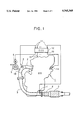
- FIG. 1 is a schematic diagram showing a construction of an exhaust gas purification system for an internal combustion engine according to one embodiment of the present invention
- FIGS. 2A to 2C are explanatory diagrams illustrating relations between the mounting position of a catalytic converter and an exhaust gas temperature in the exhaust gas purification system according to one embodiment of the present invention
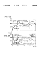
- FIGS. 3A and 3B are state transition diagrams plotting an exhaust gas temperature immediately after a cold start of the internal combustion engine at the stage before the exhaust gas purification system is applied;
- FIG. 4 is a characteristic diagram plotting an HC purification factor against the exhaust gas temperature of the catalytic converter to be used in the exhaust gas purification system;
- FIG. 5 is a characteristic diagram plotting the exhaust gas temperature against a fuel injection increase to be used in the exhaust gas purification
- FIG. 6 is a characteristic diagram plotting the HC purification factor against a fuel injection increase to be used in the exhaust gas purification system
- FIG. 7 is a characteristic diagram plotting an intake gas HC concentration against a fuel injection increase to be used in the exhaust gas purification system
- FIG. 8 is a characteristic diagram plotting an HC emission ratio against a fuel injection increase to be used in the exhaust gas purification system
- FIGS. 9A and 9B are state transition diagrams plotting an exhaust gas temperature and an HC concentration when a fuel injection increasing control is executed by applying the exhaust gas purification system.
- FIG. 10 is a flow chart showing a processing procedure of an ECU, as used in the exhaust gas purification system.
- FIG. 1 showing a construction of an exhaust gas purification system for an internal combustion engine
- an exhaust port 1a of an internal combustion engine (ICE) 1 as shown in FIG. 1
- an exhaust manifold 2 Downstream of these, there is arranged a small-sized catalytic converter 4 of small heat capacity, which is immediately followed by a catalytic converter 5 of large capacity.
- an O 2 sensor 6 In the exhaust manifold 2, there is arranged an O 2 sensor 6 for detecting the oxygen concentration in the exhaust gas.
- an exhaust temperature sensor 7 for detecting the temperature of the exhaust gas.
- an electric air pump 9 which is driven by an electric motor 8, so that secondary air is fed from the air pump 9 through a secondary air feed port 10 into the exhaust gas in the exhaust manifold 2.
- An ECU (Electronic Control Unit) 12 is used as an arithmetic logic circuit and is composed of a well-known central processing unit CPU, a ROM for storing a control program, a RAM for storing various data, an input/output circuit and a bus line for connecting the foregoing components.
- Various data 11, as coming from the O 2 sensor 6, the temperature sensor 7 and the not-shown various sensors, are read in and operated by the ECU 12 so that various signals 13 are outputted to an injector 14 and not-shown various actuators to control the running condition of the internal combustion engine 1.
- the calculation of the fuel injection rate (amount), as based upon the running condition of the internal combustion engine by the ECU 12, and the air/fuel ratio feedback control, as based upon the oxygen concentration signal indicating the oxygen concentration in the exhaust gas and coming from the O 2 sensor 6, are well known in the art so that a further description thereof is omitted for brevity.
- FIGS. 2A to 2C are a relation between a distance L mm! from the exit of the exhaust manifold 2 of the internal combustion engine 1 to the front end of the catalytic converter 4 in the exhaust gas purification system and an exhaust gas temperatures.
- the heat release from the exhaust pipe 3 increases more so that the exhaust gas temperature lowers more, as the distance from the exit of the exhaust manifold 2 increases more.
- the delay in the ignition angle and the rise in the idle speed are executed in the low speed/load running state immediately after the cold start, the temperature of the exhaust gas to flow into the catalytic converter 4 rises, but the concentration of the reacted component in the exhaust gas such as the HC (hydrocarbons) or CO (carbon monoxide) drops so that the reaction in the catalytic converter 4 after the catalyzation temperature is reached declines. As a result, it takes a long time for the catalytic converter 4 to be activated in its entirety, so that the effect of improving the exhaust gas purification is halved. If the delay of ignition angle is executed at a low running speed, on the other hand, the drivability may be deteriorated due to shortage of torque.
- FIGS. 3A and 3B Actually measured data of the exhaust gas temperature behaviors upstream and downstream of the catalytic converter 4 immediately after the cold start when no fuel injection increasing control is executed in the exhaust gas purification system are shown in FIGS. 3A and 3B.
- the catalytic converter 4 In the idle state immediately after the start, the catalytic converter 4 is activated for ten and several seconds by the delay in the ignition angle and the increase in the idle speed so that the outflow gas temperature of the catalytic converter 4 exceeds the inflow gas temperature. After this, the inflow gas temperature is lowered in the low speed/load running state after the release of the delay in the ignition angle and the increase in the idle speed, so that the catalytic converter 4 cannot keep its activated state.
- the reaction in the catalytic converter 4 is promoted to keep the activated state by controlling the increase in the fuel injection rate and the feeding rate of the secondary air to the inside of the exhaust manifold in the vicinity of the exhaust port la of the internal combustion engine 1 or the exhaust passage upstream the catalytic converter 4.
- N cf.increment.T/( ⁇ rq) mol! - - - (3).
- the exhaust gas temperature is raised from T0 to T1 when it passes through the catalytic converter 4, as described above.
- N mol! of CnHm is required in order to keep the catalytic converter 4 Activated. This requirement is satisfied by additionally feeding the increased amount of fuel to be injected as the unburned gas in the combustion chamber into the catalytic converter 4 and by feeding the oxygen necessary for the reaction in the form of the secondary air.
- the characteristics, as plotted in FIG. 6, is obtained if the relation between the fuel injection increase ⁇ and the HC purification factor ⁇ is deduced by eliminating the outflow gas temperature T1 from FIGS. 4 and 5. It is apparently seen from FIG. 6 that the HC purification factor ⁇ of the catalytic converter 4 is given the ⁇ max (the maximum HC purification factor) or about 65% according to the present embodiment by setting the fuel injection increase ⁇ , and that the outflow gas temperature T1 at this time is about 380° C., as plotted in FIG. 5, which exceeds the activation temperature of the catalyst.
- the HC emission can be reduced as a whole.
- the optimization of the HC in the exhaust gas has been described in the present embodiment, a similar optimization can be effected for the Co.
- FIGS. 9A and 9B show state transitions produced by the optimization confirming tests by applying the control of the fuel injection increase in the exhaust gas purification system of the present embodiment to an actual internal combustion engine. It is apparent from FIGS. 9A and 9B that the outflow gas temperature drops for no fuel injection increase once it exceeds the activation temperature of the catalyst but that the activated state can be kept from about 19 seconds after the start of the partial activation of the catalytic converter 4 even in the subsequent low speed/load running condition. It is further seen that the HC concentration for the outflow gas at the fuel injection increase time is accordingly far lower than that for no fuel injection increase thereby to retain the satisfactory exhaust gas purification.
- the running state of the internal combustion engine 1 is detected at step S101 on the basis of the read signals including an engine speed NE, an intake air flow QA, an intake pressure PM, a throttle opening TA, a cooling water temperature THW or other signals of the internal combustion engine 1. Then, the routine advances to step S102, at which it is decided whether or not the cooling water temperature THW is below a predetermined temperature Ts corresponding to the cold start of the engine. If the determination result at step S102 is NO or if it is not at the cold start, the present routine is ended.
- step S104 it is determined on the basis of the detected signal of the exhaust temperature sensor 7 whether or not an exhaust gas temperature Te is below a predetermined temperature Ts1 sufficient for keeping the activated state of the catalytic converter 4. If the determination at step S104 is NO indicating so that the exhaust gas temperature Te exceeds the predetermined temperature Ts1, the present routine is ended.
- step S104 determines whether or not the exhaust gas temperature Te is below the predetermined temperature Ts1
- step S107 if the determination at step S107 is YES, as exemplified by the idle state of the internal combustion engine 1, the stop state of the vehicle and the inactivated state of the catalytic converter 4, the routine advances to step S108, at which the ignition angle delaying control and the idle speed raising control are executed to effect the early warming-up control of the catalytic converter 4. Thereafter, the routine advances to step S109, at which it is determined whether the exhaust gas temperature Te has risen to a predetermined temperature Ts2 (Ts2 ⁇ Ts1) at which the influence of the cooling by feeding the secondary air can be ignored.
- Ts2 predetermined temperature
- step S109 determines whether the determination at step S109 is YES. If the determination at step S109 is YES, the routine advances to step S110, at which the air pump 9 is driven by the electric motor 8 to feed the secondary air through the secondary air feed port 10 to the inside of the exhaust manifold 2, and the present routine is ended.
- step S110 the air pump 9 is driven by the electric motor 8 to feed the secondary air through the secondary air feed port 10 to the inside of the exhaust manifold 2, and the present routine is ended.
- step S110 determines whether the determination at step S109 is NO, the operation of step S110 is skipped.
- step S111 determines whether the catalytic converter 4 is activated partially or wholly whereas the catalytic converter 5 is not sufficiently activated
- the routine advances to step S112, at which the fuel injection rate increase control is executed in the mode of the present embodiment.
- the optimum value of the fuel injection increase at this time may be either sequentially calculated by the ECU 12 reading the various signals including the detected signal of the temperature sensor 7 and on the detected engine running state or calculated a map value which is present from the various conditions.
- step S110 at which the secondary air is fed like before, and the present routine is ended.
- the fuel injection rate is increased to be richer in fuel than the stoichiometric air/fuel ratio to feed the secondary air simultaneously as a portion of the catalytic converter 4 reaches the activation temperature, so that the temperatures of the catalytic converter 4 itself and the exhaust gas can be kept over the activation temperature by the heat of the reaction of the increased fuel in the catalytic converter 4.
- the small-sized catalytic converter 4 of small heat capacity at the upstream stage is quickly activated even at the cold start of the engine so that it can be kept together with the exhaust gas temperature at the activation temperature of the catalyst, and the catalytic converter 5 of large capacity at the downstream stage can reliably purify the noxious components in the exhaust gas discharged from the internal combustion engine 1.
- the temperature sensor 7 is arranged in the vicinity of the exit of the exhaust pipe 3, the temperature sensor 7 may be replaced by a variety of sensors for detecting the running state of the internal combustion engine 1 to estimate the exhaust gas temperature from the information of the various sensors.
Landscapes
- Engineering & Computer Science (AREA)
- Chemical & Material Sciences (AREA)
- Combustion & Propulsion (AREA)
- Mechanical Engineering (AREA)
- General Engineering & Computer Science (AREA)
- Chemical Kinetics & Catalysis (AREA)
- Health & Medical Sciences (AREA)
- Toxicology (AREA)
- Exhaust Gas After Treatment (AREA)
- Electrical Control Of Air Or Fuel Supplied To Internal-Combustion Engine (AREA)
Applications Claiming Priority (2)
| Application Number | Priority Date | Filing Date | Title |
|---|---|---|---|
| JP7278926A JPH09119310A (ja) | 1995-10-26 | 1995-10-26 | 内燃機関の排ガス浄化装置 |
| JP7-278926 | 1995-10-26 |
Publications (1)
| Publication Number | Publication Date |
|---|---|
| US5765368A true US5765368A (en) | 1998-06-16 |
Family
ID=17604011
Family Applications (1)
| Application Number | Title | Priority Date | Filing Date |
|---|---|---|---|
| US08/735,053 Expired - Fee Related US5765368A (en) | 1995-10-26 | 1996-10-23 | Exhaust gas purification by gas reaction in exhaust catalyst |
Country Status (3)
| Country | Link |
|---|---|
| US (1) | US5765368A (ja) |
| JP (1) | JPH09119310A (ja) |
| DE (1) | DE19644139A1 (ja) |
Cited By (14)
| Publication number | Priority date | Publication date | Assignee | Title |
|---|---|---|---|---|
| US5836152A (en) * | 1995-01-10 | 1998-11-17 | Schatz Thermo Gastech Gmbh | Process for reducing the exhaust gas emissions of an internal combustion engine for motor vehicles with catalytic converter |
| WO2000053903A1 (en) * | 1999-03-11 | 2000-09-14 | Johnson Matthey Public Limited Company | Improvements in catalyst systems |
| US6155043A (en) * | 1998-06-30 | 2000-12-05 | Siemens Aktiengesellschaft | Method for injection duration correction in an internal combustion engine having a secondary-air system |
| US6244044B1 (en) * | 1999-09-20 | 2001-06-12 | Southwest Research Institute | Method for reducing cold-start hydrocarbon emissions in a gasoline, natural gas, or propane fueled engine |
| US6293094B1 (en) * | 1998-09-17 | 2001-09-25 | Daimlerchrysler Ag | Method for operating an internal combustion engine and system and with sulfur-rich exhaust gas purification component and an internal combustion engine system operable therewith |
| US20050039445A1 (en) * | 2001-11-02 | 2005-02-24 | Wolfgang Boerkel | Method for control secondary air amounts |
| US6915629B2 (en) * | 2002-03-07 | 2005-07-12 | General Motors Corporation | After-treatment system and method for reducing emissions in diesel engine exhaust |
| US20060120430A1 (en) * | 2004-12-06 | 2006-06-08 | Siemens Aktiengesellschaft | Method and device for checking temperature values of a temperature sensor of an internal combustion engine |
| US20100186386A1 (en) * | 2008-08-25 | 2010-07-29 | Toyota Jidosha Kabushiki Kaisha | Exhaust gas purification apparatus for internal combustion engine and method of controlling the same |
| US20100313857A1 (en) * | 2004-03-16 | 2010-12-16 | Yamaha Hatsudoki Kabushiki Kaisha | Engine with a charging system |
| US20110231079A1 (en) * | 2008-11-19 | 2011-09-22 | Tino Arlt | Method and device for operating an internal combustion engine |
| US8272208B1 (en) * | 2007-10-02 | 2012-09-25 | Brunswick Corporation | Exhaust system with air injection |
| US8806868B2 (en) * | 2011-02-17 | 2014-08-19 | GM Global Technology Operations LLC | Secondary air injection system and method |
| US8966896B2 (en) | 2011-07-19 | 2015-03-03 | GM Global Technology Operations LLC | Secondary air injection system and method |
Families Citing this family (3)
| Publication number | Priority date | Publication date | Assignee | Title |
|---|---|---|---|---|
| DE19801815A1 (de) * | 1998-01-19 | 1999-07-22 | Volkswagen Ag | Mager-Regeneration von NOx-Speichern |
| DE19959605A1 (de) * | 1999-12-10 | 2001-06-13 | Volkswagen Ag | Vorrichtung und Verfahren zur NOx- und/oder SOx-Regeneration eines NOx-Speicherkatalysators |
| DE19963930A1 (de) * | 1999-12-31 | 2001-07-12 | Bosch Gmbh Robert | Verfahren zum Betreiben einer Brennkraftmaschine insbesondere eines Kraftfahrzeugs |
Citations (11)
| Publication number | Priority date | Publication date | Assignee | Title |
|---|---|---|---|---|
| US4209981A (en) * | 1975-05-16 | 1980-07-01 | Nissan Motor Company, Limited | Method and an apparatus to control the temperature of an engine exhaust gas purifying device |
| JPS6088870A (ja) * | 1983-10-21 | 1985-05-18 | Mazda Motor Corp | エンジンの点火時期制御装置 |
| JPS60261949A (ja) * | 1984-06-08 | 1985-12-25 | Nissan Motor Co Ltd | 内燃機関の空燃比制御装置 |
| JPH0315637A (ja) * | 1989-06-14 | 1991-01-24 | Toyota Motor Corp | 内燃機関の空燃比制御装置 |
| JPH03202613A (ja) * | 1989-12-28 | 1991-09-04 | Komatsu Ltd | 内燃機関の排気触媒装置 |
| JPH0518235A (ja) * | 1991-07-12 | 1993-01-26 | Japan Electron Control Syst Co Ltd | 内燃機関の二次空気制御装置 |
| US5184463A (en) * | 1990-09-20 | 1993-02-09 | Robert Bosch Gmbh | Method of reducing the emission of toxic exhaust gas components in an internal combustion engine |
| US5483946A (en) * | 1994-11-03 | 1996-01-16 | Ford Motor Company | Engine control system with rapid catalyst warm-up |
| US5501073A (en) * | 1993-09-13 | 1996-03-26 | Honda Giken Kogyo Kabushiki Kaisha | Ignition timing control system for internal combustion engines |
| US5537321A (en) * | 1992-10-15 | 1996-07-16 | Toyota Jidosha Kabushiki Kaisha | Diagnostic apparatus for controlling the operation of a catalytic converter |
| US5577383A (en) * | 1991-09-20 | 1996-11-26 | Hitachi, Ltd. | Apparatus for controlling internal combustion engine |
-
1995
- 1995-10-26 JP JP7278926A patent/JPH09119310A/ja active Pending
-
1996
- 1996-10-23 DE DE19644139A patent/DE19644139A1/de not_active Ceased
- 1996-10-23 US US08/735,053 patent/US5765368A/en not_active Expired - Fee Related
Patent Citations (11)
| Publication number | Priority date | Publication date | Assignee | Title |
|---|---|---|---|---|
| US4209981A (en) * | 1975-05-16 | 1980-07-01 | Nissan Motor Company, Limited | Method and an apparatus to control the temperature of an engine exhaust gas purifying device |
| JPS6088870A (ja) * | 1983-10-21 | 1985-05-18 | Mazda Motor Corp | エンジンの点火時期制御装置 |
| JPS60261949A (ja) * | 1984-06-08 | 1985-12-25 | Nissan Motor Co Ltd | 内燃機関の空燃比制御装置 |
| JPH0315637A (ja) * | 1989-06-14 | 1991-01-24 | Toyota Motor Corp | 内燃機関の空燃比制御装置 |
| JPH03202613A (ja) * | 1989-12-28 | 1991-09-04 | Komatsu Ltd | 内燃機関の排気触媒装置 |
| US5184463A (en) * | 1990-09-20 | 1993-02-09 | Robert Bosch Gmbh | Method of reducing the emission of toxic exhaust gas components in an internal combustion engine |
| JPH0518235A (ja) * | 1991-07-12 | 1993-01-26 | Japan Electron Control Syst Co Ltd | 内燃機関の二次空気制御装置 |
| US5577383A (en) * | 1991-09-20 | 1996-11-26 | Hitachi, Ltd. | Apparatus for controlling internal combustion engine |
| US5537321A (en) * | 1992-10-15 | 1996-07-16 | Toyota Jidosha Kabushiki Kaisha | Diagnostic apparatus for controlling the operation of a catalytic converter |
| US5501073A (en) * | 1993-09-13 | 1996-03-26 | Honda Giken Kogyo Kabushiki Kaisha | Ignition timing control system for internal combustion engines |
| US5483946A (en) * | 1994-11-03 | 1996-01-16 | Ford Motor Company | Engine control system with rapid catalyst warm-up |
Cited By (18)
| Publication number | Priority date | Publication date | Assignee | Title |
|---|---|---|---|---|
| US5836152A (en) * | 1995-01-10 | 1998-11-17 | Schatz Thermo Gastech Gmbh | Process for reducing the exhaust gas emissions of an internal combustion engine for motor vehicles with catalytic converter |
| US6155043A (en) * | 1998-06-30 | 2000-12-05 | Siemens Aktiengesellschaft | Method for injection duration correction in an internal combustion engine having a secondary-air system |
| US6293094B1 (en) * | 1998-09-17 | 2001-09-25 | Daimlerchrysler Ag | Method for operating an internal combustion engine and system and with sulfur-rich exhaust gas purification component and an internal combustion engine system operable therewith |
| DE19842625C2 (de) * | 1998-09-17 | 2003-03-27 | Daimler Chrysler Ag | Verfahren zum Betrieb einer Verbrennungsmotoranlage mit schwefelanreichernder Abgasreinigungskomponente und damit betreibbare Verbrennungsmotoranlage |
| WO2000053903A1 (en) * | 1999-03-11 | 2000-09-14 | Johnson Matthey Public Limited Company | Improvements in catalyst systems |
| US6651424B1 (en) | 1999-03-11 | 2003-11-25 | Johnson Matthey Public Limited | Catalyst systems |
| US6244044B1 (en) * | 1999-09-20 | 2001-06-12 | Southwest Research Institute | Method for reducing cold-start hydrocarbon emissions in a gasoline, natural gas, or propane fueled engine |
| US7520125B2 (en) * | 2001-11-02 | 2009-04-21 | Robert Bosch Gmbh | Method for controlling the amount of secondary air |
| US20050039445A1 (en) * | 2001-11-02 | 2005-02-24 | Wolfgang Boerkel | Method for control secondary air amounts |
| US6915629B2 (en) * | 2002-03-07 | 2005-07-12 | General Motors Corporation | After-treatment system and method for reducing emissions in diesel engine exhaust |
| US20100313857A1 (en) * | 2004-03-16 | 2010-12-16 | Yamaha Hatsudoki Kabushiki Kaisha | Engine with a charging system |
| US7380983B2 (en) * | 2004-12-06 | 2008-06-03 | Siemens Aktiengesellschaft | Method and device for checking temperature values of a temperature sensor of an internal combustion engine |
| US20060120430A1 (en) * | 2004-12-06 | 2006-06-08 | Siemens Aktiengesellschaft | Method and device for checking temperature values of a temperature sensor of an internal combustion engine |
| US8272208B1 (en) * | 2007-10-02 | 2012-09-25 | Brunswick Corporation | Exhaust system with air injection |
| US20100186386A1 (en) * | 2008-08-25 | 2010-07-29 | Toyota Jidosha Kabushiki Kaisha | Exhaust gas purification apparatus for internal combustion engine and method of controlling the same |
| US20110231079A1 (en) * | 2008-11-19 | 2011-09-22 | Tino Arlt | Method and device for operating an internal combustion engine |
| US8806868B2 (en) * | 2011-02-17 | 2014-08-19 | GM Global Technology Operations LLC | Secondary air injection system and method |
| US8966896B2 (en) | 2011-07-19 | 2015-03-03 | GM Global Technology Operations LLC | Secondary air injection system and method |
Also Published As
| Publication number | Publication date |
|---|---|
| DE19644139A1 (de) | 1997-04-30 |
| JPH09119310A (ja) | 1997-05-06 |
Similar Documents
| Publication | Publication Date | Title |
|---|---|---|
| US5765368A (en) | Exhaust gas purification by gas reaction in exhaust catalyst | |
| US7730718B2 (en) | Control system for internal combustion engine | |
| US6311482B1 (en) | Air-fuel ratio control apparatus for internal combustion engines | |
| US8302378B2 (en) | Degradation diagnosis device for catalyst | |
| US20040221571A1 (en) | Diesel aftertreatment systems | |
| US6205776B1 (en) | Air-fuel ration control system for multi-cylinder internal combustion engine | |
| US5388402A (en) | Secondary air supply control system for internal combustion engines | |
| JPH09236569A (ja) | 内燃機関の排気浄化装置の機能診断装置 | |
| US6880329B2 (en) | Exhaust gas purifying system for internal combustion engines | |
| US5493857A (en) | Exhaust gas-purifying system for internal combustion engines | |
| EP1895131B1 (en) | Abnormality determination apparatus and method for temperature detector | |
| JP2962127B2 (ja) | 内燃機関の制御装置 | |
| JP3774910B2 (ja) | 内燃機関の排気ガス浄化装置 | |
| JP2004060563A (ja) | 内燃機関の燃料噴射量制御装置 | |
| US7107762B2 (en) | Secondary air supplying apparatus | |
| JP2003120382A (ja) | 内燃機関の触媒早期暖機制御システムの異常診断装置 | |
| JP2003176714A (ja) | 内燃機関の排気浄化装置の機能診断装置 | |
| JP2000310140A (ja) | 内燃機関の空燃比制御装置 | |
| EP2233725B1 (en) | Elevated-temperature operation controller for internal-combustion engine | |
| JP4547617B2 (ja) | 内燃機関の二次空気供給システムの異常診断装置 | |
| JP2005002974A (ja) | 排気ガスセンサのヒータ制御装置 | |
| JP3216265B2 (ja) | 触媒の活性化判定装置 | |
| JP4706977B2 (ja) | 内燃機関の排気浄化装置の劣化診断装置 | |
| US7313912B2 (en) | Secondary air supply system for internal combustion engine | |
| JP4061676B2 (ja) | 内燃機関の2次空気供給装置における自己診断装置 |
Legal Events
| Date | Code | Title | Description |
|---|---|---|---|
| AS | Assignment |
Owner name: DENSO CORPORATION, JAPAN Free format text: ASSIGNMENT OF ASSIGNORS INTEREST;ASSIGNORS:MATSUMOTO, TOSHIKI;HODAIRA, KINJI;REEL/FRAME:008281/0480 Effective date: 19961001 |
|
| FPAY | Fee payment |
Year of fee payment: 4 |
|
| FPAY | Fee payment |
Year of fee payment: 8 |
|
| REMI | Maintenance fee reminder mailed | ||
| LAPS | Lapse for failure to pay maintenance fees | ||
| STCH | Information on status: patent discontinuation |
Free format text: PATENT EXPIRED DUE TO NONPAYMENT OF MAINTENANCE FEES UNDER 37 CFR 1.362 |
|
| FP | Lapsed due to failure to pay maintenance fee |
Effective date: 20100616 |