US5784085A - Ink jet print head with flexible wall member having low and high elasticity portions - Google Patents
Ink jet print head with flexible wall member having low and high elasticity portions Download PDFInfo
- Publication number
- US5784085A US5784085A US08/533,934 US53393495A US5784085A US 5784085 A US5784085 A US 5784085A US 53393495 A US53393495 A US 53393495A US 5784085 A US5784085 A US 5784085A
- Authority
- US
- United States
- Prior art keywords
- flexible wall
- pressure generating
- wall member
- print head
- flow path
- Prior art date
- Legal status (The legal status is an assumption and is not a legal conclusion. Google has not performed a legal analysis and makes no representation as to the accuracy of the status listed.)
- Expired - Fee Related
Links
Images


Classifications
-
- B—PERFORMING OPERATIONS; TRANSPORTING
- B41—PRINTING; LINING MACHINES; TYPEWRITERS; STAMPS
- B41J—TYPEWRITERS; SELECTIVE PRINTING MECHANISMS, i.e. MECHANISMS PRINTING OTHERWISE THAN FROM A FORME; CORRECTION OF TYPOGRAPHICAL ERRORS
- B41J2/00—Typewriters or selective printing mechanisms characterised by the printing or marking process for which they are designed
- B41J2/005—Typewriters or selective printing mechanisms characterised by the printing or marking process for which they are designed characterised by bringing liquid or particles selectively into contact with a printing material
- B41J2/01—Ink jet
- B41J2/135—Nozzles
- B41J2/14—Structure thereof only for on-demand ink jet heads
- B41J2/14201—Structure of print heads with piezoelectric elements
- B41J2/14274—Structure of print heads with piezoelectric elements of stacked structure type, deformed by compression/extension and disposed on a diaphragm
-
- B—PERFORMING OPERATIONS; TRANSPORTING
- B41—PRINTING; LINING MACHINES; TYPEWRITERS; STAMPS
- B41J—TYPEWRITERS; SELECTIVE PRINTING MECHANISMS, i.e. MECHANISMS PRINTING OTHERWISE THAN FROM A FORME; CORRECTION OF TYPOGRAPHICAL ERRORS
- B41J2/00—Typewriters or selective printing mechanisms characterised by the printing or marking process for which they are designed
- B41J2/005—Typewriters or selective printing mechanisms characterised by the printing or marking process for which they are designed characterised by bringing liquid or particles selectively into contact with a printing material
- B41J2/01—Ink jet
- B41J2/135—Nozzles
- B41J2/14—Structure thereof only for on-demand ink jet heads
- B41J2002/14387—Front shooter
-
- B—PERFORMING OPERATIONS; TRANSPORTING
- B41—PRINTING; LINING MACHINES; TYPEWRITERS; STAMPS
- B41J—TYPEWRITERS; SELECTIVE PRINTING MECHANISMS, i.e. MECHANISMS PRINTING OTHERWISE THAN FROM A FORME; CORRECTION OF TYPOGRAPHICAL ERRORS
- B41J2/00—Typewriters or selective printing mechanisms characterised by the printing or marking process for which they are designed
- B41J2/005—Typewriters or selective printing mechanisms characterised by the printing or marking process for which they are designed characterised by bringing liquid or particles selectively into contact with a printing material
- B41J2/01—Ink jet
- B41J2/135—Nozzles
- B41J2/14—Structure thereof only for on-demand ink jet heads
- B41J2002/14419—Manifold
Definitions
- the present invention relates to an ink jet print head in use with an image forming apparatus of the type in which ink is jetted in the form of ink droplets from nozzle openings to an image recording medium, thereby forming an image of ink thereon.
- Examples of this type of the image forming apparatus are printers, copying machines, facsimile machines, and machines each having the functions of those machines.
- This type of the image forming apparatus has the following advantageous features. 1) It operates at low noise. 2) The cost to manufacture and the running cost are both low. 3) It is well adaptable for the color printing. With those features, the image forming apparatus rapidly increases its market share.
- each pressure generating chamber is hermetically covered with a flexible wall member, which is fixedly supported at both ends.
- An electromechanical transducing element, or the piezoelectric vibrating element is constructed such that piezoelectric vibrating members and electrode members are alternately layered in a state that a high elasticity portion formed on the flexible wall member intervenes therebetween.
- a displacement of the piezoelectric vibrating element is transmitted to the pressure generating chamber.
- the pressure generating chamber when receiving the displacement, expands or compresses, so that ink contained in the chamber is shot forth in the form of ink droplet, through the nozzle opening.
- a pressure is caused by making use of a mechanical oscillation of the member of large elastic modulus. Because of this, a low elasticity portion for converting a displacement of the electromechanical transducing element into a variation of the volume of the pressure generating chamber, is required for the ink jet print head.
- the pressure generating chamber is thinned at a portion thereof in the vicinity of the nozzle opening and the ink supply path.
- the amount of ink droplet may be increased with respect to the quantity of displacement of the electromechanical transducing element.
- a response rate of the pressure generating chamber is reduced since the natural period of the pressure generating chamber is caused to be long by the compliance thereof by the low elasticity portion.
- each pixel is printed by area modulation, viz., supposedly shooting forth a plural number of ink droplets, thereby increasing an effective print density.
- the pressure generating chamber has the low elasticity portion of a relatively large area.
- minute dots are formed in order to effect the area modulation, ink is improperly shot forth or no ink is shot forth because the compliance of the pressure generating chamber is excessively large with respect to the quantity of the displacement of the electromechanical transducing element.
- an object of the present invention is to provide an ink jet print head in which the amount of ink droplet by one shooting operation of ink is reduced, and the pressure generating chamber is driven at high speed, whereby printing by area modulation is realized.
- an ink jet print head having a flow path forming member with pressure generating chambers, ink supply paths, and reservoirs, a nozzle plate for covering one side of the flow path forming member, the nozzle plate having nozzle openings communicating with pressure generating chambers, a flexible wall member for varying the volumes of the pressure generating chambers, the flexible wall member covering the other side of the flow path forming member, and piezoelectric vibrating elements for elastically deforming the flexible wall member, the piezoelectric vibrating elements being in contact with the flexible wall member.
- the ink jet print head is improved in that the flexible wall member includes low elasticity portions and high elasticity portions for transmitting expanding and compressing motions of the piezoelectric vibrating elements to the pressure generating chambers, one end of each high elasticity portion being extended to a region of the ink supply path.
- the compliance of the pressure generating chamber defined substantially by the low elasticity portion, is dispersed into the ink supply path and the reservoir.
- the pressure loss in the pressure generating chamber is reduced.
- Ink can be shot forth by a minute displacement of the electromechanical transducing element.
- a variation of the volume of the pressure generating chamber is reduced, and hence the amount of jetted ink is reduced.
- reduction of the compliance of the pressure generating chamber leads to reduction of the ink jetting period, so that one pixel can be printed by a plural number of ink droplets for area tone.
- FIG. 1 is a perspective view showing an embodiment of an ink jet print head according to the present invention
- FIG. 2A is a cross sectional view showing a portion of the ink jet print head of FIG. 1 in the vicinity of the pressure generating chambers;
- FIG. 2B is a plan view showing a flexible wall member used in the ink jet print head of FIG. 1;
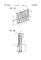
- FIG. 3A is a perspective view showing an assembly of laminated piezoelectric vibrating elements, used in the ink jet print head;
- FIG. 3B is a sectional view showing the assembly of laminated piezoelectric vibrating elements shown in FIG. 3A;
- FIG. 4 is a perspective view showing another embodiment of an ink jet print head according to the present invention.
- FIG. 5A is a cross sectional view showing a portion of the ink jet print head of FIG. 4 in the vicinity of the pressure generating chambers;
- FIG. 5B is a plan view showing a flexible wall member used in the ink jet print head of FIG. 4;
- FIG. 6 is a cross sectional view showing a portion of another ink jet print head in the vicinity of the pressure generating chambers.
- FIG. 7 is a cross sectional view showing a portion of yet another ink jet print head in the vicinity of the pressure generating chambers.
- FIGS. 1 and 2 show an embodiment of an ink jet print head according to the present invention.
- a nozzle forming member 2, a flow path forming member 3, and a flexible wall member 10 are coupled into an assembly.
- the assembly is fastened to a frame member 8 (FIG. 2).
- the nozzle forming member 2 includes a plural number of nozzle openings 1.
- the flow path forming member 3 includes pressure generating chambers 4 communicating with the nozzle openings 1, ink supply paths 5, and reservoirs 6.
- the flexible wall member 10 includes low elasticity portions 11 and high elasticity portions 12. Each of the low elasticity portions 11 of approximately 2 ⁇ m thick is formed by selectively patterning a stainless steel of 20 to 0.30 ⁇ m thick by etching process, for example.
- the flexible wall member 10 is supported by the frame member 8 and the flow path forming member 3 at the outer ends of the pressure generating chambers 4 and at the outer ends of the reservoirs 6.
- Each of the high elasticity portions 12 has such a rigidity as to reliability transmit a displacement of the piezoelectric vibrating element 7 to the pressure generating chamber 4.
- One end 12a of the high elasticity portion 12, located closer to the nozzle opening 1, is extended to a location where it faces the flow path forming member 3, while the other end 12b thereof is extended up to a region of the ink supply path 5.
- Each low,elasticity portion 11 extends from a part of portion of the wall member 10 facing the pressure generating chamber 4 associated therewith, i.e., from one side of the flexible wall member 10 not including the portion where the high elasticity portion 12 is formed (see FIG. 2B), to a portion facing the reservoir 6 beyond the ink supply paths 5.
- Reference numeral 9 designates partition walls which partition the pressure generating chambers 4.
- Precision press work work by examiner laser, an electroforming process by nickel, and anisotropic etching process are preferable examples of working the nozzle forming member 2 and the flow path forming member 3.
- each of the laminated type piezoelectric vibrating elements 7 is bonded to the high elasticity portion 12 by welding, for example.
- piezoelectric layers 14 and electrode layers 15 and 16 are laminated such that each piezoelectric layer 14 is sandwiched between its adjacent electrode layers.
- the piezoelectric layer 14, made of piezoelectric material has the thickness of 20 to 30 ⁇ m.
- Each of the electrode layers 15 and 16, made of suitable electrode material has the thickness of 2 to 5 ⁇ m.
- the piezoelectric vibrating element 7 vibrates in d31 mode; it displaces in the direction orthogonal to the laminating direction.
- piezoelectric vibrating elements 7 are fastened at one end to a base member 13, to form a piezoelectric vibrator unit, for ease of assembling of the resultant head.
- the piezoelectric vibrating elements 7 are arrayed at pitches equal to those of the nozzle openings 1 in their array.
- Electrodes 17 and 18 are mounted respectively on the bottom and the top of the piezoelectric vibrator unit.
- the electrodes 15 are connected to the electrodes 17 at the bottom of the piezoelectric vibrator unit, and the electrodes 17 are individual electrodes.
- the electrodes 16 are connected to the electrodes 18 at the top of the piezoelectric vibrator unit, and the electrodes 18 are connected together to the common electrode 19.
- a distance L12a between the first end 12a of the high elasticity portion 12 and the piezoelectric vibrating element 7 is selected such that a reaction force of the flexible wall member 10 when it receives a displacement force from the piezoelectric vibrating element 7 is reduced to 1/100.
- the distance L12a becomes shorter, the second end 12b of the high elasticity portion 12 is more greatly displaced.
- it is necessary to optimize this distance by taking account of the displacement efficiency and a reaction acting on the bonding face.
- the piezoelectric vibrating element 7 contracts. Then, the high elasticity portion 12, of which the first end 12a extends to a region of the nozzle opening 1 and the second end 12b extends to a region of the ink supply paths 5, is deformed by the compliance of the low elasticity portion 11 of the ink supply paths 5 and the reservoirs 6. As a result, the pressure generating chamber 4 is expanded.
- the drive signal to the piezoelectric vibrating element 7 is stopped. Then, the piezoelectric vibrating element 7 is expanded, and the pressure generating chamber 4 is contracted. Also in this case, the high elasticity portion 12, of which the first end 12a extends to a region of the nozzle opening 1 and the second end 12b extends to a region of the ink supply path 5 and beyond the ink supply path 5, is deformed with the aid of the compliance of the low elasticity portion 11 of the ink supply path 5 and the reservoir 6. As a result, the pressure generating chamber 4 of a low compliance is contracted.
- both ends 12a and 12b of the high elasticity portion 12 may be extended to a region of the flow path forming member 3, as shown in FIG. 4.
- This modification further reduces the compliance of the pressure generating chamber 4.
- the amount of ink droplet by one shooting operation of ink is reduced, and a high response of the pressure generating chamber 4 is realized.
- reference numeral 30 designates a flow path forming member.
- a space is defined by the flow path forming member 30, a nozzle plate 37 with a nozzle 36, and a flexible member 38.
- a pressure generating chamber 31 two reservoirs 32 and 33, and ink supply paths 34 and 35 are formed.
- the reservoirs 32 and 33 are disposed on both sides of the pressure generating chamber 31.
- the pressure generating chamber 31 communicates with the reservoir 32 through the ink supply path 34.
- the pressure generating chamber 31 communicates with the reservoir 33 through the ink supply path 35.
- the flexible member 38 includes high elasticity portions 40 and low elasticity portions 39.
- the high elasticity portion 40 is extended at both ends to reach a frame member 41.
- the high elasticity portion 40 is located between the paired low elasticity portions 39 when viewed in the width direction of the pressure generating chamber 31.
- the high elasticity portion 40 receives a displacement of a piezoelectric vibrating element 42 through a pressure transmission member 42a, which is extended in the longitudinal direction of the pressure generating chamber 31, and varies the volume of the pressure generating chamber 31.
- one side of the high elasticity portion 40 is extended from one end of the pressure generating chamber 31 to the frame member 41 beyond the ink supply path 34 and the reservoir 32, while the other side thereof is extended from the other end of the pressure generating chamber 31 to the frame member 41 beyond the ink supply path 35 and the reservoir 33.
- the paired low elasticity portions 39 are located on both sides of the high elasticity portion 40.
- the compliance of the pressure generating chamber 31 is defined by only the paired low elasticity portions 39 that are located on both sides of the pressure generating chamber 31. Because of this, it is extremely small. The ink amount reduction and the high response of the pressure generating chamber are both achieved.
- the piezoelectric vibrating element 42 is provided with the pressure transmission member 42a.
- the pressure transmission member 42a With provision of the pressure transmission member 42a, a displacement force is uniformly distributed over the entire high elasticity portion 40. For this reason, the high elasticity portion 40 is constructed as a continuous member extended to reach the frame member 41. Further, since both the ends of the pressure transmission member 42a are formed to extend up to the ink supply paths 34 and 35 as shown in FIG. 5A, the compliance of the pressure generating chamber 31 can be made lower.
- low elasticity portions 44 are formed in the portions of the flexible member 38 which partially define the reservoirs 32 and 33 and are apart from the pressure generating chamber 31, as shown in FIG. 6. The low elasticity portions 44 assist the high elasticity portion 40 to vary the volume of the pressure generating chamber 31.
- a displacement d31 of the piezoelectric vibrating element in the direction orthogonal to the electric field is used.
- a piezoelectric vibrating element 54 vibrating in a d33 mode may also be used as shown in FIG. 7.
- the piezoelectric vibrating element 54 is constructed such that electrodes 51 and 52, and piezoelectric members 53 are alternately layered while being oriented in its desired displacing direction.
- the flexible wall member for varying the volumes of the pressure generating chambers which hermetically covers the second side of the flow path forming member, includes low elasticity portions and high elasticity portions for transmitting expanding and compressing motions of the piezoelectric vibrating elements to the pressure generating chambers, one end of each high elasticity portion being extended up to a region of the flow path forming member, which is located closer to the nozzle opening, and the other end thereof being extended at least to a region of the ink supply path.
- the compliance of the low elasticity portion which occupies most of the compliance of the print head, is dispersed into the ink supply paths and the reservoirs. Accordingly, ink can be shot forth by a minute displacement of the electromechanical transducing element. The reduced amount of jetted ink and a high response of the print head are both realized.
- the low elasticity portion which substantially determines the compliance of the print head, is located in the region of the reservoir, which has a larger area than the pressure generating chamber.
- This construction brings about many advantages. For example, formation of the low elasticity portion is easy. The shooting speed of the ink droplet is increased, the amount of the jetted ink is reduced, and a variation of the frequency of the head drive signal is minimized since those low elasticity portions do not take part in the jetting of ink.
- the vibrating plate which serves as a mere rigid plate in the regions of the ink supply path and the reservoir, gives rise to the compliance in those regions. Therefore, the necessary amount of jetting ink necessary for the print is secured without elongating the pressure generating chamber.
- the high density array of the nozzle openings is realized without enlarging the print head.
Landscapes
- Particle Formation And Scattering Control In Inkjet Printers (AREA)
Applications Claiming Priority (6)
| Application Number | Priority Date | Filing Date | Title |
|---|---|---|---|
| JP6-229747 | 1994-09-26 | ||
| JP22974894 | 1994-09-26 | ||
| JP6-229748 | 1994-09-26 | ||
| JP22974794 | 1994-09-26 | ||
| JP7-262237 | 1995-09-14 | ||
| JP26223795A JP3484841B2 (ja) | 1994-09-26 | 1995-09-14 | インクジェット式記録ヘッド |
Publications (1)
| Publication Number | Publication Date |
|---|---|
| US5784085A true US5784085A (en) | 1998-07-21 |
Family
ID=27331559
Family Applications (1)
| Application Number | Title | Priority Date | Filing Date |
|---|---|---|---|
| US08/533,934 Expired - Fee Related US5784085A (en) | 1994-09-26 | 1995-09-26 | Ink jet print head with flexible wall member having low and high elasticity portions |
Country Status (4)
| Country | Link |
|---|---|
| US (1) | US5784085A (de) |
| EP (1) | EP0703078B1 (de) |
| JP (1) | JP3484841B2 (de) |
| DE (1) | DE69524513T2 (de) |
Cited By (5)
| Publication number | Priority date | Publication date | Assignee | Title |
|---|---|---|---|---|
| US6497476B1 (en) * | 1998-10-12 | 2002-12-24 | Matsushita Electric Industrial Co., Ltd. | Liquid injection device, manufacturing method therefor, liquid injection method and manufacturing method for piezo-electric actuator |
| US20030016273A1 (en) * | 2000-03-27 | 2003-01-23 | Fujitsu Limited | Multi-nozzle ink jet head and manufacturing method thereof |
| US6616270B1 (en) * | 1998-08-21 | 2003-09-09 | Seiko Epson Corporation | Ink jet recording head and ink jet recording apparatus comprising the same |
| US20050285911A1 (en) * | 2004-06-29 | 2005-12-29 | Brother Kogyo Kabushiki Kaisha | Liquid delivering device |
| US20100321424A1 (en) * | 2009-06-22 | 2010-12-23 | Brother Kogyo Kabushiki Kaisha | Liquid ejecting apparatus |
Families Citing this family (8)
| Publication number | Priority date | Publication date | Assignee | Title |
|---|---|---|---|---|
| JP2861980B2 (ja) * | 1997-01-30 | 1999-02-24 | 日本電気株式会社 | インク滴噴射装置 |
| JP3456380B2 (ja) * | 1997-09-02 | 2003-10-14 | 株式会社村田製作所 | 圧電アクチュエータ |
| JP2000218787A (ja) | 1999-01-29 | 2000-08-08 | Seiko Epson Corp | インクジェット式記録ヘッド及び画像記録装置 |
| DE60201300T2 (de) | 2001-07-09 | 2006-02-23 | Ricoh Co., Ltd. | Flüssigkeitstropfenstrahlkopf und Tintenstrahlaufzeichnungsgerät |
| JP4670205B2 (ja) * | 2001-08-24 | 2011-04-13 | リコープリンティングシステムズ株式会社 | インクジェットヘッド |
| US7264338B2 (en) * | 2003-03-24 | 2007-09-04 | Ricoh Company, Ltd. | Recording head, carriage and image forming apparatus |
| JP5130100B2 (ja) * | 2007-06-19 | 2013-01-30 | 株式会社リコー | 液体吐出ヘッド及び画像形成装置 |
| JP5715345B2 (ja) * | 2010-03-03 | 2015-05-07 | 富士フイルム株式会社 | 液体吐出ヘッド |
Citations (7)
| Publication number | Priority date | Publication date | Assignee | Title |
|---|---|---|---|---|
| JPH0331141A (ja) * | 1989-06-28 | 1991-02-08 | Canon Inc | プリンター装置 |
| JPH041052A (ja) * | 1990-02-23 | 1992-01-06 | Seiko Epson Corp | インクジェット式記録ヘッド、圧電振動体、及びこれらの製造方法 |
| US5424769A (en) * | 1992-06-05 | 1995-06-13 | Seiko Epson Corporation | Ink jet recording head |
| US5539982A (en) * | 1992-03-03 | 1996-07-30 | Seiko Epson Corporation | Method of manufacturing an ink jet recording head |
| US5560090A (en) * | 1993-08-20 | 1996-10-01 | Kabushiki Kaisha Tec | Method of fabricating ink jet print head |
| US5594475A (en) * | 1993-08-27 | 1997-01-14 | Kabushiki Kaisha Tec | Ink jet printer head and a method of driving the same |
| US5617127A (en) * | 1992-12-04 | 1997-04-01 | Ngk Insulators, Ltd. | Actuator having ceramic substrate with slit(s) and ink jet print head using the actuator |
-
1995
- 1995-09-14 JP JP26223795A patent/JP3484841B2/ja not_active Expired - Lifetime
- 1995-09-26 US US08/533,934 patent/US5784085A/en not_active Expired - Fee Related
- 1995-09-26 DE DE69524513T patent/DE69524513T2/de not_active Expired - Fee Related
- 1995-09-26 EP EP95115167A patent/EP0703078B1/de not_active Expired - Lifetime
Patent Citations (7)
| Publication number | Priority date | Publication date | Assignee | Title |
|---|---|---|---|---|
| JPH0331141A (ja) * | 1989-06-28 | 1991-02-08 | Canon Inc | プリンター装置 |
| JPH041052A (ja) * | 1990-02-23 | 1992-01-06 | Seiko Epson Corp | インクジェット式記録ヘッド、圧電振動体、及びこれらの製造方法 |
| US5539982A (en) * | 1992-03-03 | 1996-07-30 | Seiko Epson Corporation | Method of manufacturing an ink jet recording head |
| US5424769A (en) * | 1992-06-05 | 1995-06-13 | Seiko Epson Corporation | Ink jet recording head |
| US5617127A (en) * | 1992-12-04 | 1997-04-01 | Ngk Insulators, Ltd. | Actuator having ceramic substrate with slit(s) and ink jet print head using the actuator |
| US5560090A (en) * | 1993-08-20 | 1996-10-01 | Kabushiki Kaisha Tec | Method of fabricating ink jet print head |
| US5594475A (en) * | 1993-08-27 | 1997-01-14 | Kabushiki Kaisha Tec | Ink jet printer head and a method of driving the same |
Cited By (13)
| Publication number | Priority date | Publication date | Assignee | Title |
|---|---|---|---|---|
| US6966635B2 (en) | 1998-08-21 | 2005-11-22 | Seiko Epson Corporation | Ink jet recording head and ink jet recording apparatus comprising the same |
| US6616270B1 (en) * | 1998-08-21 | 2003-09-09 | Seiko Epson Corporation | Ink jet recording head and ink jet recording apparatus comprising the same |
| US20030206218A1 (en) * | 1998-08-21 | 2003-11-06 | Seiko Epson Corporation | Ink jet recording head and ink jet recording apparatus comprising the same |
| US6497476B1 (en) * | 1998-10-12 | 2002-12-24 | Matsushita Electric Industrial Co., Ltd. | Liquid injection device, manufacturing method therefor, liquid injection method and manufacturing method for piezo-electric actuator |
| US20030016273A1 (en) * | 2000-03-27 | 2003-01-23 | Fujitsu Limited | Multi-nozzle ink jet head and manufacturing method thereof |
| US6921159B2 (en) * | 2000-03-27 | 2005-07-26 | Fuji Photo Film Co., Ltd. | Multi-nozzle ink jet head and manufacturing method thereof |
| US20050168538A1 (en) * | 2000-03-27 | 2005-08-04 | Fuji Photo Film Co., Ltd. | Multi-nozzle ink jet head and manufacturing method thereof |
| US7134172B2 (en) | 2000-03-27 | 2006-11-14 | Fuji Photo Film Co., Ltd. | Method of manufacturing a multi-nozzle ink jet head |
| US20050285911A1 (en) * | 2004-06-29 | 2005-12-29 | Brother Kogyo Kabushiki Kaisha | Liquid delivering device |
| US7654649B2 (en) | 2004-06-29 | 2010-02-02 | Brother Kogyo Kabushiki Kaisha | Liquid delivering device |
| US20100321424A1 (en) * | 2009-06-22 | 2010-12-23 | Brother Kogyo Kabushiki Kaisha | Liquid ejecting apparatus |
| US8562118B2 (en) * | 2009-06-22 | 2013-10-22 | Brother Kogyo Kabushiki Kaisha | Liquid ejecting apparatus |
| US9302488B2 (en) | 2009-06-22 | 2016-04-05 | Brother Kogyo Kabushiki Kaisha | Liquid ejecting apparatus |
Also Published As
| Publication number | Publication date |
|---|---|
| EP0703078A2 (de) | 1996-03-27 |
| EP0703078B1 (de) | 2001-12-12 |
| DE69524513D1 (de) | 2002-01-24 |
| JPH08150716A (ja) | 1996-06-11 |
| DE69524513T2 (de) | 2002-08-22 |
| JP3484841B2 (ja) | 2004-01-06 |
| EP0703078A3 (de) | 1997-03-12 |
Similar Documents
| Publication | Publication Date | Title |
|---|---|---|
| US5144342A (en) | Head for ink-jet printer | |
| US5784085A (en) | Ink jet print head with flexible wall member having low and high elasticity portions | |
| EP0677386B1 (de) | Farbstrahlaufzeichnungskopf | |
| JP3386119B2 (ja) | 積層型インクジェット記録ヘッドの流路ユニット | |
| JP2009160841A (ja) | 液体噴射ヘッドの製造方法及び液体噴射ヘッド並びに液体噴射装置 | |
| US6467885B2 (en) | Ink jet record head | |
| US4788557A (en) | Ink jet method and apparatus for reducing cross talk | |
| EP1306216B1 (de) | Piezoelektrische Vibratoreinheit | |
| US6007189A (en) | Piezoelectric type ink-jet printing head having a pressure chamber plate which is less flexible than piezoelectric elements | |
| JPH09314832A (ja) | インクジェットヘッド | |
| JP2870462B2 (ja) | インクジェット記録ヘッド | |
| JP3161026B2 (ja) | インクジェット式印字ヘッド駆動方法 | |
| JP2002086724A (ja) | インクジェット式記録ヘッド及びインクジェット式記録装置 | |
| JP3339288B2 (ja) | インクジェット式記録ヘッド | |
| JP3681288B2 (ja) | インクジェットヘッド及びインクジェット記録装置 | |
| JPH0729425B2 (ja) | インクジェット記録ヘッド | |
| JP2003182076A (ja) | インクジェット式記録ヘッド及びインクジェット式記録装置 | |
| JP2000190497A (ja) | インクジェット式記録ヘッド及びインクジェット式記録装置 | |
| JP3412156B2 (ja) | インクジェット記録ヘッド | |
| JP4639492B2 (ja) | インクジェット式記録ヘッド及びインクジェット式記録装置 | |
| JP2000108348A (ja) | インクジェット式記録ヘッド、及びこれを用いた画像形成装置 | |
| JP3381790B2 (ja) | 積層型インクジェット記録ヘッドの圧力発生ユニット | |
| JP3381791B2 (ja) | 積層型インクジェット記録ヘッドの圧力発生ユニットの製造方法 | |
| JP2988265B2 (ja) | インクジェット式プリンタヘッド及びその駆動方法 | |
| JPH09295403A (ja) | インクジェットヘッド |
Legal Events
| Date | Code | Title | Description |
|---|---|---|---|
| FEPP | Fee payment procedure |
Free format text: PAYOR NUMBER ASSIGNED (ORIGINAL EVENT CODE: ASPN); ENTITY STATUS OF PATENT OWNER: LARGE ENTITY |
|
| FPAY | Fee payment |
Year of fee payment: 4 |
|
| FPAY | Fee payment |
Year of fee payment: 8 |
|
| REMI | Maintenance fee reminder mailed | ||
| LAPS | Lapse for failure to pay maintenance fees | ||
| STCH | Information on status: patent discontinuation |
Free format text: PATENT EXPIRED DUE TO NONPAYMENT OF MAINTENANCE FEES UNDER 37 CFR 1.362 |
|
| FP | Lapsed due to failure to pay maintenance fee |
Effective date: 20100721 |