US5789997A - Bypassable wilkinson divider - Google Patents
Bypassable wilkinson divider Download PDFInfo
- Publication number
- US5789997A US5789997A US08/776,758 US77675897A US5789997A US 5789997 A US5789997 A US 5789997A US 77675897 A US77675897 A US 77675897A US 5789997 A US5789997 A US 5789997A
- Authority
- US
- United States
- Prior art keywords
- transmission line
- port
- power divider
- combiner
- divider
- Prior art date
- Legal status (The legal status is an assumption and is not a legal conclusion. Google has not performed a legal analysis and makes no representation as to the accuracy of the status listed.)
- Expired - Lifetime
Links
Images



Classifications
-
- H—ELECTRICITY
- H01—ELECTRIC ELEMENTS
- H01P—WAVEGUIDES; RESONATORS, LINES, OR OTHER DEVICES OF THE WAVEGUIDE TYPE
- H01P5/00—Coupling devices of the waveguide type
- H01P5/12—Coupling devices having more than two ports
- H01P5/16—Conjugate devices, i.e. devices having at least one port decoupled from one other port
Definitions
- the invention relates to high-frequency engineering, more exactly to power dividers used in microwave and radio engineering.
- the same switching device has to be used either as a power divider from one input port into two output ports or as a lossless transmission line from one input port into one output port as required at each time.
- selection devices such as bridges, placed on circuit boards.
- a surface-mounted resistor of zero ohms can operate as a bridging component suitable for industrial mass production.
- Standard junction lines also conventionally called bond wires can also be used.
- FIG. 1A One generally used passive switching device is a so-called Wilkinson divider.
- the operation of a standard Wilkinson divider appears from FIG. 1A.
- the figure shows a situation in which the signal splits from one input port into two output ports.
- the divider can be used also in the opposite way for combining a signal from two input ports into one output port.
- the Wilkinson divider When operating as a power divider, the Wilkinson divider comprises an input port IN, output ports OUTI and OUT2, a T-junction 1, a transmission line 2 connecting the input port IN and the output port OUT1, and a transmission line 3 connecting the input port IN and the output port OUT2.
- the output ports OUT1 and OUT2 are further connected by a resistor R.
- the length of the transmission lines is a quarter of wavelength.
- the characteristic impedance of the input port IN is Z 0 .
- the characteristic impedances of the output ports OUTI and OUT2 are Z 1 and Z 2 , respectively.
- the characteristic impedance of the transmission line 2 is ⁇ 2Z 0 Z 1 and, correspondingly, the characteristic impedance of the transmission line 3 is ⁇ 2Z 0 Z 2
- the impedance of the resistor R is then 2 ⁇ Z 1 Z 2 .
- FIGS. 1A, 1B, 2A and 2B A known arrangement for transforming the Wilkinson divider into a lossless transmission line is disclosed in FIGS. 1A, 1B, 2A and 2B.
- the circuit in FIG. 1B comprises a transmission line 5 with respect to FIG. 1A and bridging devices B1 to B5.
- FIG. 2A shows how the Wilkinson divider thus transformed is transformed into a Wilkinson divider according to FIG. 1A.
- the resistor R and the bridges B1, B4 and B5 are installed, but not the bridges B2 and B3.
- the transmission line 5 has in this case no effect on the operation of the divider.
- FIG. 2B It is shown in FIG. 2B how the Wilkinson divider is bypassed, that is, transformed into a lossless transmission line.
- the resistor R is not installed, nor the bridges B1, B4 and B5.
- the circuit shown in FIG. 2B is a lossless transmission line between the input port IN and the output port OUT1.
- a disadvantage of the circuit according to FIG. 1B is e.g., the great number (five in this embodiment) of bridging places operating as selection devices and the great number of installed bridges (three in divider use, two as a transmission path).
- a further disadvantage of the prior art circuit is that the bridges B2 and B3 required for operating as a transmission path cannot be easily produced with small stray impedances since they combine wide lines.
- Another disadvantage of the prior art circuit becomes evident when the input port IN and the output ports OUTI and OUT2 are not opposite to one another, especially when the Wilkinson divider is folded to reduce its size. Especially in cases such as this, it is difficult or even impossible to fit a wide transmission line within the divider.
- the arrangement cannot be used at all when the divider is simultaneously being used as an impedance adapter, that is, Z 1 ⁇ Z 0 .
- the object of the present invention is to provide a power divider which can be installed flexibly, with small changes either as a divider or as a lossless transmission line and which does not share the problems associated with the prior art arrangement described above.
- the object is achieved with the arrangement according to the characterizing part of an arrangement in which the configuration of the power divider into a lossless transmission line is realized by a parallel connection of two non-symmetrical transmission lines which usually have different impedances.
- One of the transmission lines is a branch present in the Wilkinson divider and the other is an extra branch formed inside the divider.
- FIG. 1A shows a standard Wilkinson divider
- FIG. 1B shows a prior art way of transforming the Wilkinson divider into a lossless transmission path
- FIG. 2A illustrates a switching device shown in FIG. 1B installed as a Wilkinson divider
- FIG. 2B illustrates a switching device shown in FIG. 1B installed as a lossless transmission path
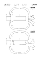
- FIG. 3A shows a modified Wilkinson divider according to the invention
- FIG. 3B shows a modified Wilkinson divider according to the invention folded into as small a space as possible
- FIG. 3C shows how a coupling device can be folded so that its transmission lines are not situated in the same place.
- FIG. 4A shows a switching device according to the invention installed as a Wilkinson divider
- FIG. 4B shows a switching device according to the invention installed as a lossless transmission path.
- the idea of the invention is to implement a transmission line with a characteristic impedance Z 0 by a parallel (i.e., an electrically parallel) connection of two narrow high-impedance transmission lines: one transmission line 2 with an impedance Z 0 ⁇ 2, which is already present in a standard Wilkinson divider, and another transmission line 4 with an impedance 2Z 0 /(2- ⁇ 2).
- the latter impedance cannot be produced on most substrates without special procedures.
- One such procedure is to etch ground plane from under the 170 ⁇ line 4.
- Non-splitting operation is studied in FIG. 4B.
- the bridge B1 and the resistor R are not installed but the bridges B2 and B3 are installed.
- the signal meets the parallel connection of the transmission lines 2 and 4 of a quarter of wavelength, the impedances of which are Z 0/ ⁇ 2 and 2Z 0 /(2- ⁇ 2), respectively.
- a quarter-wavelength long transmission line with the impedance Z 0 is produced by the parallel connection of the impedances.
- FIG. 3B shows how a modified Wilkinson divider according to the invention can be folded in order to minimize the space it takes up on a circuit board.
- FIG 3C shows how a coupling device can be folded so that its transmission lines are not situated on the same plane.
- transmission line 3 is shown, comprising a section 3 which has been drawn with dotted lines and which is located on a different plane than the rest of transmission line 3.
- An advantage of the solution according to the invention is that the Wilkinson divider on the same circuit board can be used as required at each time both in splitting and non-splitting operation which will reduce the required number of different circuit boards. Also, in the solution according to the invention a smaller number of bridges and places for bridges are needed than in prior art solutions.
- a further advantage of the solution according to the invention is that very little stray impedance is produced as bridges are needed only in high-impedance lines.
- Another advantage is that the extra line needed in the Wilkinson divider can easily be fitted into a limited space since the extra line is very narrow.
- the extra line 4 may also run close to the branch 2 in the Wilkinson divider, as long as the connection is taken into consideration in planning. See e.g. Matthaei, Young and Jones, Microwave fllters, impedance-matching networks and coupling structures, Artech House Books, 1980, Figure 5.09-1, p. 219. By means of meandering, a quarter-wavelength long line can be placed into the available space.
- a power divider such as a Wilkinson divider
- the same component substrate such as a circuit board
- transmission lines such as microstrips, suspended substrate microstrips, striplines, coaxial lines, coplanar waveguides or combinations of the above mentioned.
- transmission lines and bridging devices are not restricted to the example described above, but the field of the invention can vary within the scope of the claims.
Landscapes
- Waveguides (AREA)
- Variable-Direction Aerials And Aerial Arrays (AREA)
- Measuring Instrument Details And Bridges, And Automatic Balancing Devices (AREA)
- Control Of Electrical Variables (AREA)
- Emergency Protection Circuit Devices (AREA)
- Direct Current Feeding And Distribution (AREA)
- Tubes (AREA)
- Cable Transmission Systems, Equalization Of Radio And Reduction Of Echo (AREA)
- Waveguide Switches, Polarizers, And Phase Shifters (AREA)
Applications Claiming Priority (3)
| Application Number | Priority Date | Filing Date | Title |
|---|---|---|---|
| FI952796A FI98418C (fi) | 1995-06-07 | 1995-06-07 | Ohitettava Wilkinsonin tehojakaja |
| FI952796 | 1995-06-07 | ||
| PCT/FI1996/000325 WO1996041396A1 (en) | 1995-06-07 | 1996-05-31 | Bypassable wilkinson divider |
Publications (1)
| Publication Number | Publication Date |
|---|---|
| US5789997A true US5789997A (en) | 1998-08-04 |
Family
ID=8543557
Family Applications (1)
| Application Number | Title | Priority Date | Filing Date |
|---|---|---|---|
| US08/776,758 Expired - Lifetime US5789997A (en) | 1995-06-07 | 1996-05-31 | Bypassable wilkinson divider |
Country Status (9)
| Country | Link |
|---|---|
| US (1) | US5789997A (de) |
| EP (1) | EP0774171B1 (de) |
| JP (1) | JPH10504161A (de) |
| AT (1) | ATE204405T1 (de) |
| AU (1) | AU706738B2 (de) |
| DE (1) | DE69614484T2 (de) |
| FI (1) | FI98418C (de) |
| NO (1) | NO970558D0 (de) |
| WO (1) | WO1996041396A1 (de) |
Cited By (8)
| Publication number | Priority date | Publication date | Assignee | Title |
|---|---|---|---|---|
| WO2001080350A1 (en) * | 2000-04-13 | 2001-10-25 | Raytheon Company | Suspended transmission line with embedded signal channeling device |
| US6507320B2 (en) | 2000-04-12 | 2003-01-14 | Raytheon Company | Cross slot antenna |
| US6518844B1 (en) | 2000-04-13 | 2003-02-11 | Raytheon Company | Suspended transmission line with embedded amplifier |
| US6535088B1 (en) | 2000-04-13 | 2003-03-18 | Raytheon Company | Suspended transmission line and method |
| US6552635B1 (en) | 2000-04-13 | 2003-04-22 | Raytheon Company | Integrated broadside conductor for suspended transmission line and method |
| US6622370B1 (en) | 2000-04-13 | 2003-09-23 | Raytheon Company | Method for fabricating suspended transmission line |
| US6885264B1 (en) | 2003-03-06 | 2005-04-26 | Raytheon Company | Meandered-line bandpass filter |
| WO2016153591A1 (en) * | 2015-03-25 | 2016-09-29 | Raytheon Company | Expandable analog manifold |
Families Citing this family (1)
| Publication number | Priority date | Publication date | Assignee | Title |
|---|---|---|---|---|
| JP6361288B2 (ja) * | 2014-05-30 | 2018-07-25 | 船井電機株式会社 | 分配回路 |
Citations (6)
| Publication number | Priority date | Publication date | Assignee | Title |
|---|---|---|---|---|
| US3904990A (en) * | 1974-06-07 | 1975-09-09 | Hazeltine Corp | N-way power divider with remote isolating resistors |
| EP0095808A1 (de) * | 1982-05-28 | 1983-12-07 | Laboratoires D'electronique Et De Physique Appliquee L.E.P. | Mikrowellen Richtungskoppler mit vier Übertragungsleitungen und in ähnlicher Weise ausgeführte passive Leistungsverteilerschaltung |
| US4616196A (en) * | 1985-01-28 | 1986-10-07 | Rca Corporation | Microwave and millimeter wave switched-line type phase shifter including exponential line portion |
| DE3640937A1 (de) * | 1986-11-29 | 1988-06-01 | Licentia Gmbh | Mikrowellen-leistungsteiler |
| US4901042A (en) * | 1987-04-01 | 1990-02-13 | Tokyo Keiki Co. | High frequency power divider |
| DE4241148A1 (en) * | 1991-12-09 | 1993-06-17 | Murata Manufacturing Co | Directional coupler with stripline electrodes on stacked substrates - has multilayer chip structure with external electrodes connected to ends of quarter-wavelength series stripline combination |
-
1995
- 1995-06-07 FI FI952796A patent/FI98418C/fi active
-
1996
- 1996-05-31 AU AU58234/96A patent/AU706738B2/en not_active Ceased
- 1996-05-31 AT AT96919845T patent/ATE204405T1/de not_active IP Right Cessation
- 1996-05-31 US US08/776,758 patent/US5789997A/en not_active Expired - Lifetime
- 1996-05-31 WO PCT/FI1996/000325 patent/WO1996041396A1/en not_active Ceased
- 1996-05-31 DE DE69614484T patent/DE69614484T2/de not_active Expired - Fee Related
- 1996-05-31 EP EP96919845A patent/EP0774171B1/de not_active Expired - Lifetime
- 1996-05-31 JP JP9500176A patent/JPH10504161A/ja active Pending
-
1997
- 1997-02-06 NO NO970558A patent/NO970558D0/no not_active Application Discontinuation
Patent Citations (6)
| Publication number | Priority date | Publication date | Assignee | Title |
|---|---|---|---|---|
| US3904990A (en) * | 1974-06-07 | 1975-09-09 | Hazeltine Corp | N-way power divider with remote isolating resistors |
| EP0095808A1 (de) * | 1982-05-28 | 1983-12-07 | Laboratoires D'electronique Et De Physique Appliquee L.E.P. | Mikrowellen Richtungskoppler mit vier Übertragungsleitungen und in ähnlicher Weise ausgeführte passive Leistungsverteilerschaltung |
| US4616196A (en) * | 1985-01-28 | 1986-10-07 | Rca Corporation | Microwave and millimeter wave switched-line type phase shifter including exponential line portion |
| DE3640937A1 (de) * | 1986-11-29 | 1988-06-01 | Licentia Gmbh | Mikrowellen-leistungsteiler |
| US4901042A (en) * | 1987-04-01 | 1990-02-13 | Tokyo Keiki Co. | High frequency power divider |
| DE4241148A1 (en) * | 1991-12-09 | 1993-06-17 | Murata Manufacturing Co | Directional coupler with stripline electrodes on stacked substrates - has multilayer chip structure with external electrodes connected to ends of quarter-wavelength series stripline combination |
Cited By (11)
| Publication number | Priority date | Publication date | Assignee | Title |
|---|---|---|---|---|
| US6507320B2 (en) | 2000-04-12 | 2003-01-14 | Raytheon Company | Cross slot antenna |
| WO2001080350A1 (en) * | 2000-04-13 | 2001-10-25 | Raytheon Company | Suspended transmission line with embedded signal channeling device |
| US6518844B1 (en) | 2000-04-13 | 2003-02-11 | Raytheon Company | Suspended transmission line with embedded amplifier |
| US6535088B1 (en) | 2000-04-13 | 2003-03-18 | Raytheon Company | Suspended transmission line and method |
| US6542048B1 (en) | 2000-04-13 | 2003-04-01 | Raytheon Company | Suspended transmission line with embedded signal channeling device |
| US6552635B1 (en) | 2000-04-13 | 2003-04-22 | Raytheon Company | Integrated broadside conductor for suspended transmission line and method |
| US6608535B2 (en) | 2000-04-13 | 2003-08-19 | Raytheon Company | Suspended transmission line with embedded signal channeling device |
| US6622370B1 (en) | 2000-04-13 | 2003-09-23 | Raytheon Company | Method for fabricating suspended transmission line |
| US6885264B1 (en) | 2003-03-06 | 2005-04-26 | Raytheon Company | Meandered-line bandpass filter |
| WO2016153591A1 (en) * | 2015-03-25 | 2016-09-29 | Raytheon Company | Expandable analog manifold |
| US9622108B2 (en) | 2015-03-25 | 2017-04-11 | Raytheon Company | Expandable analog manifold |
Also Published As
| Publication number | Publication date |
|---|---|
| FI952796L (fi) | 1996-12-08 |
| DE69614484D1 (de) | 2001-09-20 |
| WO1996041396A1 (en) | 1996-12-19 |
| JPH10504161A (ja) | 1998-04-14 |
| NO970558L (no) | 1997-02-06 |
| FI98418C (fi) | 1997-06-10 |
| AU5823496A (en) | 1996-12-30 |
| FI952796A0 (fi) | 1995-06-07 |
| AU706738B2 (en) | 1999-06-24 |
| EP0774171A1 (de) | 1997-05-21 |
| DE69614484T2 (de) | 2002-04-25 |
| ATE204405T1 (de) | 2001-09-15 |
| NO970558D0 (no) | 1997-02-06 |
| EP0774171B1 (de) | 2001-08-16 |
| FI98418B (fi) | 1997-02-28 |
Similar Documents
| Publication | Publication Date | Title |
|---|---|---|
| US5455545A (en) | Compact low-loss microwave balun | |
| US5264860A (en) | Metal flared radiator with separate isolated transmit and receive ports | |
| US3516024A (en) | Interdigitated strip line coupler | |
| Tanaka et al. | Slot-coupled directional couplers between double-sided substrate microstrip lines and their applications | |
| US4902992A (en) | Millimeter-wave multiplexers | |
| US6078227A (en) | Dual quadrature branchline in-phase power combiner and power splitter | |
| US6636126B1 (en) | Four port hybrid | |
| US5235296A (en) | Directional coupler using a microstrip line | |
| US4862120A (en) | Wideband stripline to microstrip transition | |
| US5097233A (en) | Coplanar 3dB quadrature coupler | |
| US8174338B2 (en) | Impedance transforming hybrid coupler | |
| US5412354A (en) | Single layer double ring hybrid magic-tee | |
| US12087993B2 (en) | Broadband and low cost printed circuit board based 180° hybrid couplers on a single layer board | |
| US3991390A (en) | Series connected stripline balun | |
| US6778037B1 (en) | Means for handling high-frequency energy | |
| EP0774171B1 (de) | Überbrückbarer leistungsteiler | |
| EP1346432B1 (de) | Vierport-hybrid-mikrostreifenschaltung des lange-typs | |
| KR930004493B1 (ko) | 플래너 에어스트립라인-스트립라인 매직-t회로망 장치 | |
| GB2170358A (en) | Microwave power divider | |
| US6411175B1 (en) | Power distribution/synthesis apparatus | |
| KR20070089579A (ko) | 스터브 소자를 이용한 다단 마이크로스트립 브랜치 라인결합기 | |
| KR20020012935A (ko) | 3단 체비셰프 매칭변환기를 이용한 전력분배기/합성기 | |
| US20060119452A1 (en) | Apparatuses for coupling radio frequency signal power | |
| JPS6345901A (ja) | 方向性結合器 | |
| CN1155946A (zh) | 可旁路的威尔金森分配器 |
Legal Events
| Date | Code | Title | Description |
|---|---|---|---|
| AS | Assignment |
Owner name: NOKIA TELECOMMUNICATIONS OY, FINLAND Free format text: ASSIGNMENT OF ASSIGNORS INTEREST;ASSIGNOR:DEKKER, ANDRE P.;REEL/FRAME:008583/0916 Effective date: 19970107 |
|
| AS | Assignment |
Owner name: NOKIA TELECOMMUNICATIONS OY, FINLAND Free format text: CORRECTIVE ASSIGNMENT TO CORRECT ASSIGNEE'S ADDRESS PREVIOUSLY RECORDED ON REEL 8583, FRAME 0916;ASSIGNOR:DEKKER, ANDRE P.;REEL/FRAME:008675/0259 Effective date: 19970107 |
|
| STCF | Information on status: patent grant |
Free format text: PATENTED CASE |
|
| FPAY | Fee payment |
Year of fee payment: 4 |
|
| FPAY | Fee payment |
Year of fee payment: 8 |
|
| FPAY | Fee payment |
Year of fee payment: 12 |
|
| AS | Assignment |
Owner name: NOKIA NETWORKS OY, FINLAND Free format text: CHANGE OF NAME;ASSIGNOR:NOKIA TELECOMMUNICATIONS OY;REEL/FRAME:037095/0847 Effective date: 19990930 Owner name: NOKIA CORPORATION, FINLAND Free format text: MERGER;ASSIGNOR:NOKIA NETWORKS OY;REEL/FRAME:037096/0790 Effective date: 20011001 Owner name: NOKIA TECHNOLOGIES OY, FINLAND Free format text: ASSIGNMENT OF ASSIGNORS INTEREST;ASSIGNOR:NOKIA CORPORATION;REEL/FRAME:037097/0045 Effective date: 20150116 |