US5799733A - Early evaluation system with pump and method of servicing a well - Google Patents
Early evaluation system with pump and method of servicing a well Download PDFInfo
- Publication number
- US5799733A US5799733A US08/941,883 US94188397A US5799733A US 5799733 A US5799733 A US 5799733A US 94188397 A US94188397 A US 94188397A US 5799733 A US5799733 A US 5799733A
- Authority
- US
- United States
- Prior art keywords
- pump
- fluid
- sampling tube
- packer
- tubing string
- Prior art date
- Legal status (The legal status is an assumption and is not a legal conclusion. Google has not performed a legal analysis and makes no representation as to the accuracy of the status listed.)
- Expired - Lifetime
Links
- 238000000034 method Methods 0.000 title claims abstract description 78
- 238000011156 evaluation Methods 0.000 title claims abstract description 58
- 239000012530 fluid Substances 0.000 claims abstract description 287
- 238000005070 sampling Methods 0.000 claims abstract description 258
- 230000015572 biosynthetic process Effects 0.000 claims abstract description 153
- 238000004891 communication Methods 0.000 claims abstract description 139
- 238000005553 drilling Methods 0.000 claims abstract description 51
- 238000005086 pumping Methods 0.000 claims description 31
- 230000008859 change Effects 0.000 claims description 23
- 238000007789 sealing Methods 0.000 claims description 20
- 230000000750 progressive effect Effects 0.000 claims description 16
- 230000000717 retained effect Effects 0.000 claims description 3
- 230000004936 stimulating effect Effects 0.000 claims description 3
- 238000005259 measurement Methods 0.000 abstract description 18
- 238000005755 formation reaction Methods 0.000 description 126
- 238000012360 testing method Methods 0.000 description 62
- 238000004519 manufacturing process Methods 0.000 description 17
- 230000002706 hydrostatic effect Effects 0.000 description 7
- 239000000243 solution Substances 0.000 description 7
- 238000004364 calculation method Methods 0.000 description 6
- 230000005484 gravity Effects 0.000 description 6
- 230000000704 physical effect Effects 0.000 description 6
- 238000010276 construction Methods 0.000 description 4
- 239000000706 filtrate Substances 0.000 description 4
- 238000012544 monitoring process Methods 0.000 description 4
- 230000035699 permeability Effects 0.000 description 4
- 238000013459 approach Methods 0.000 description 3
- 230000006835 compression Effects 0.000 description 3
- 238000007906 compression Methods 0.000 description 3
- 230000003247 decreasing effect Effects 0.000 description 3
- 238000002347 injection Methods 0.000 description 3
- 239000007924 injection Substances 0.000 description 3
- 239000000126 substance Substances 0.000 description 3
- 238000012546 transfer Methods 0.000 description 3
- 238000005516 engineering process Methods 0.000 description 2
- 238000013100 final test Methods 0.000 description 2
- 239000000203 mixture Substances 0.000 description 2
- 230000008569 process Effects 0.000 description 2
- 238000012545 processing Methods 0.000 description 2
- 238000012956 testing procedure Methods 0.000 description 2
- 239000004215 Carbon black (E152) Substances 0.000 description 1
- 239000002253 acid Substances 0.000 description 1
- 230000003213 activating effect Effects 0.000 description 1
- 230000005540 biological transmission Effects 0.000 description 1
- 238000009530 blood pressure measurement Methods 0.000 description 1
- 239000004568 cement Substances 0.000 description 1
- 238000011109 contamination Methods 0.000 description 1
- 230000008878 coupling Effects 0.000 description 1
- 238000010168 coupling process Methods 0.000 description 1
- 238000005859 coupling reaction Methods 0.000 description 1
- 229930195733 hydrocarbon Natural products 0.000 description 1
- 150000002430 hydrocarbons Chemical class 0.000 description 1
- 230000007774 longterm Effects 0.000 description 1
- 239000007787 solid Substances 0.000 description 1
Images


Classifications
-
- E—FIXED CONSTRUCTIONS
- E21—EARTH OR ROCK DRILLING; MINING
- E21B—EARTH OR ROCK DRILLING; OBTAINING OIL, GAS, WATER, SOLUBLE OR MELTABLE MATERIALS OR A SLURRY OF MINERALS FROM WELLS
- E21B49/00—Testing the nature of borehole walls; Formation testing; Methods or apparatus for obtaining samples of soil or well fluids, specially adapted to earth drilling or wells
- E21B49/08—Obtaining fluid samples or testing fluids, in boreholes or wells
- E21B49/087—Well testing, e.g. testing for reservoir productivity or formation parameters
- E21B49/088—Well testing, e.g. testing for reservoir productivity or formation parameters combined with sampling
-
- E—FIXED CONSTRUCTIONS
- E21—EARTH OR ROCK DRILLING; MINING
- E21B—EARTH OR ROCK DRILLING; OBTAINING OIL, GAS, WATER, SOLUBLE OR MELTABLE MATERIALS OR A SLURRY OF MINERALS FROM WELLS
- E21B21/00—Methods or apparatus for flushing boreholes, e.g. by use of exhaust air from motor
- E21B21/10—Valve arrangements in drilling-fluid circulation systems
- E21B21/103—Down-hole by-pass valve arrangements, i.e. between the inside of the drill string and the annulus
-
- E—FIXED CONSTRUCTIONS
- E21—EARTH OR ROCK DRILLING; MINING
- E21B—EARTH OR ROCK DRILLING; OBTAINING OIL, GAS, WATER, SOLUBLE OR MELTABLE MATERIALS OR A SLURRY OF MINERALS FROM WELLS
- E21B27/00—Containers for collecting or depositing substances in boreholes or wells, e.g. bailers, baskets or buckets for collecting mud or sand; Drill bits with means for collecting substances, e.g. valve drill bits
- E21B27/02—Dump bailers, i.e. containers for depositing substances, e.g. cement or acids
-
- E—FIXED CONSTRUCTIONS
- E21—EARTH OR ROCK DRILLING; MINING
- E21B—EARTH OR ROCK DRILLING; OBTAINING OIL, GAS, WATER, SOLUBLE OR MELTABLE MATERIALS OR A SLURRY OF MINERALS FROM WELLS
- E21B33/00—Sealing or packing boreholes or wells
- E21B33/10—Sealing or packing boreholes or wells in the borehole
- E21B33/12—Packers; Plugs
- E21B33/124—Units with longitudinally-spaced plugs for isolating the intermediate space
- E21B33/1243—Units with longitudinally-spaced plugs for isolating the intermediate space with inflatable sleeves
-
- E—FIXED CONSTRUCTIONS
- E21—EARTH OR ROCK DRILLING; MINING
- E21B—EARTH OR ROCK DRILLING; OBTAINING OIL, GAS, WATER, SOLUBLE OR MELTABLE MATERIALS OR A SLURRY OF MINERALS FROM WELLS
- E21B49/00—Testing the nature of borehole walls; Formation testing; Methods or apparatus for obtaining samples of soil or well fluids, specially adapted to earth drilling or wells
- E21B49/08—Obtaining fluid samples or testing fluids, in boreholes or wells
- E21B49/081—Obtaining fluid samples or testing fluids, in boreholes or wells with down-hole means for trapping a fluid sample
Definitions
- the present invention relates generally to methods and apparatus for servicing a well, and more particularly, to methods and apparatus for the early evaluation of a well after the borehole has been drilled and before casing has been cemented in the borehole wherein the apparatus utilizes a pump to move fluid therethrough.
- One very commonly used well testing procedure is to first cement a casing in the borehole and then to perforate the casing adjacent zones of interest. Subsequently, the well is flow-tested through the perforations. Such flow tests are commonly performed with a drill stem test string which is a string of tubing located within the casing.
- the drill stem test string carries packers, tester valves, circulating valves and the like to control the flow of fluids through the drill stem test string.
- drill stem testing of cased wells provides very good test data, it has the disadvantage that the well must first be cased before the test can be conducted. Also, better reservoir data can often be obtained immediately after the well is drilled and before the formation has been severely damaged by drilling fluids and the like.
- this type of test string is undesirable for use offshore because the pipe string can become stuck in the open borehole due to differential pressures between the borehole and various formations.
- portions of the pipe string will lay against the side of the borehole and sometimes a differential pressure situation will be encountered wherein the pipe string becomes very tightly stuck against the sidewall of the borehole. This is an especially dangerous problem when the flow control valves of the test string are operated by manipulation of the test string. In these situations, if the test string becomes stuck, it may be impossible to control the flow of fluid through the test string.
- a similar procedure may be carried out using a straddle packer with compressible packer elements.
- Use of this device has the additional disadvantage of requiring that the packer be supported on the bottom of the hole or that a sidewall anchor is required.
- pad-type wireline testers which simply press a small resilient pad against the sidewall of the borehole and take a very small unidirectional sample through an orifice in the pad.
- An example of such a pad-type tester is shown in U.S. Pat. No. 3,577,781 to Lebourg.
- the primary disadvantage of pad-type testers is that they take a very small unidirectional sample which is often not truly representative of the formation and which provides very little data on the production characteristics of the formation. It is also sometimes difficult to seal the pad. When the pad does seal, it is subject to differential sticking and sometimes the tool may be damaged when it is removed.
- a system including an outer tubing string having an inflatable packer, a communication passage disposed through the tubing string below the packer, an inflation passage communicated with the inflatable element of the packer, and an inflation valve controlling flow of inflation fluid through the inflation passage.
- the inflation valve is constructed so that the opening and closing of the inflation valve is controlled by surface manipulation of the outer tubing string.
- the inflatable packer can be set in the well simply by manipulation of the outer tubing string and applying fluid pressure to the tubing string without running an inner well tool into the tubing string.
- an inner well tool such as a surge chamber, may be run into and engaged with the outer tubing string to place the inner well tool in fluid communication with a subsurface formation through the communication passage.
- a straddle packer having upper and lower packer elements which are engaged on opposite sides of the formation.
- the well fluid samples are collected by running an inner tubing string, preferably an inner coiled tubing string, into the previously described outer tubing string.
- the coiled tubing string is engaged with the outer tubing string, and the bore of the coiled tubing string is communicated with a subsurface formation through the circulation passage defined in the outer tubing string. Then well fluid from the subsurface is flowed through the communication passage and up the coiled tubing string.
- a coiled tubing string may include various valves for control of fluid flow therethrough.
- This prior invention may also be used to treat a subsurface formation.
- a pressure injection canister may be run into and engaged with the outer tubing string.
- the pressurized injection canister is communicated with the subsurface formation through the circulation passage.
- a treatment fluid such as acid can then be injected into the subsurface formation.
- the present invention presents improvements on the prior art by providing a sampling tube with multiple, independently activated samplers in communication therewith. Electronic instruments may also be placed in communication with the sampling tube to measure and/or record pressure, temperature, fluid resistivity, and other fluid properties.
- a formation pump is preferably located above the sampling tube and is used to draw fluid through the tube. The pump may be operated by a variety of means.
- Typical tests conducted with a drill string test string are known as draw-down and build-up tests.
- draw-down a tester valve in the drill stem test string is opened, and the well is allowed to flow up through the drill string until the formation pressure is drawn down to a minimum level.
- build-up the tester valve is closed, and the formation pressure is allowed to build up below the tester valve to a maximum pressure.
- draw-down and build-up tests may take many days to complete.
- One technique that has been used is to pull the drill pipe out of the wellbore when it is desired to test a subterranean zone or formation penetrated by the wellbore and to then run special test string into the well for testing the zone or formation. This, of course, involves the time and cost of pulling and running pipe and is disadvantageous from that standpoint.
- the integrated well drilling and evaluation systems of this prior invention basically comprise a drill string, a drill bit carried on a lower end of the drill string for drilling a wellbore, a logging while drilling instrument included in the drill string for generating data indicative of the hydrocarbon productive nature of subsurface zones and formations intersected by the wellbore so that a zone or formation of interest may be identified without removing the drill string from the wellbore, a packer carried on the drill string above the drill bit for sealing the zone or formation of interest between the drill string and the wellbore, and a testing means included in the drill string which provides a valve for isolating and testing the zone or formation of interest, whereby the well can be drilled, logged and tested without removing the drill string from the wellbore.
- the sampling chamber and formation pump are included in the drill string.
- Upper and lower circulation control valves allow the fluid to be pumped downwardly through the drill bit during a drilling operation and then shut off from the drill bit and opened between packers on the drill string so that a formation pump in the drill string may be actuated to flow formation fluid through a chamber containing samplers and instrumentation.
- the purpose of the early evaluation system is to measure formation pressure, obtain a fluid sample and measure fluid properties during the sampling process to verify that the sample is representative of formation fluid. These operations can be performed at several depths, on one trip of the drill pipe, in an open borehole, before the well is cased. This information is important to well operators because knowledge of formation pressures and obtaining representative formation fluid samples are key to making the decision whether to plug and abandon a well, or to case the well and spend additional resources on it.
- a pump is utilized to flow fluid into a sampling chamber where the samples may be obtained and the fluid properties measured.
- the early evaluation system of the present invention includes an apparatus for use in servicing a well having an uncased borehole intersecting a subsurface zone of interest.
- the apparatus comprises an outer tubing string, a housing adjacent to the outer tubing string and defining a sampling tube therein, a packer adjacent the housing and adapted for sealing the borehole on a side of the formation, and a formation pump disposed in the housing for flowing fluids from the formation through the sampling tube.
- the packer is an inflatable packer.
- the packer is a straddle packer having a pair of inflatable packer elements for sealing the wellbore on opposite sides of the formation.
- An equalizing means is provided for equalizing pressure on opposite sides of the packer elements when the straddle packer is engaged with the wellbore.
- the pump is mechanically actuated.
- the pump may be a progressive cavity pump having a shaft extending from a rotor thereof. The shaft is connected to the outer tubing string, and the outer tubing string is rotated with respect to the housing to actuate the pump. Bearing means may be provided between the outer tubing string and the housing to facilitate rotation.
- the pump may also be a reciprocating pump comprising a cylinder portion forming part of the housing and a plunger portion slidably disposed in the cylinder portion and connected to the outer tubing string. In this reciprocating embodiment, the outer tubing string is reciprocated with respect to the cylinder portion to actuate the pump.
- This reciprocating configuration might be reversed with the cylinder being connected to the tubing string and the plunger forming a part of the housing so that the cylinder portion is reciprocated with respect to the plunger portion.
- the pump may be driven by an electric motor.
- Other mechanical configurations may also be used.
- the pump is hydraulically actuated.
- the apparatus further comprises a hydraulic motor connected to the pump, and the hydraulic motor is actuated by pumping fluid down through the outer tubing string, thereby activating the pump.
- the hydraulic motor may also be a progressive cavity device.
- the apparatus preferably comprises a plurality of fluid samplers in communication with the sampling tube so that individual fluid samples may be taken and retained. Also, recording and measuring instruments may be in communication with the sampling tube whereby fluid characteristics of the formation may be measured and retained.
- the apparatus may further comprise a telemetry system disposed in the housing whereby measured fluid data from the apparatus may be sent to the surface in real time while circulating fluid.
- a longitudinal passage is defined through the pump and packer. A portion of this longitudinal passage may be formed by the sampling tube.
- a sampling port is defined in the packer and is in communication with the formation when the packer is engaged with the wellbore.
- a drill bit is connected to a lower end of the packer.
- This embodiment preferably further comprises an upper circulating valve having a first position wherein the outer tubing string is in communication with the longitudinal passage and a second position wherein the outer tubing string is isolated from the longitudinal passage, and a lower circulating valve having a first position wherein the sampling tube is in communication with the drill bit and isolated from the sampling port and a second position wherein the sampling tube is in communication with the sampling port and isolated from the drill bit.
- the upper and lower circulating valves When the upper and lower circulating valves are in the first positions thereof, drilling fluid pumped down the outer tubing string is discharged adjacent to the drill bit so that drilling operations may be carried out. After drilling, the upper and lower circulating valves may be actuated to the second positions thereof, and the pump is then actuated for flowing fluid from the formation fluid through the sampling port into the sampling tube and to the samplers wherein fluid samples and measurements may be taken as previously described.
- the present invention also includes a method of servicing a well having an uncased borehole intersecting a subsurface zone or formation of interest.
- the method comprises the steps of running an evaluation tool into the well wherein the evaluation tool comprises an outer tubing string, a housing adjacent to the outer tubing string and having a sampling tube therein, a packer connected to the housing, a communication passage communicating the sampling tube with a borehole below the packer, and a formation pump in communication with the sampling tube.
- the packer has an inflatable packer element
- the evaluation tool further comprises an inflation passage communicating the inflatable element with an interior of the outer tubing string, and an inflation valve having an open position wherein the inflation passage is open and having a closed position wherein the inflation passage is closed.
- the method further comprises the steps of setting the packer in the borehole above the subsurface zone or formation and actuating the pump so that fluid is flowed from the borehole below the packer through the communication passage and sampling tube.
- the step of setting the packer may include inflating the inflatable element with an inflation valve in the open position thereof by increasing fluid pressure in the interior of the outer tubing string, after which the inflation valve is closed to maintain the packer in the borehole.
- the step of actuating the pump is carried out after closing the inflation valve.
- the inflation step includes setting the upper and lower packer elements above and below the subsurface zone or formation, respectively.
- the method may further comprise the step of trapping a fluid sample in a sampler in communication with the sampling tube and repeating the pumping and trapping steps as necessary to trap additional well fluid samples.
- the pump does not pump fluid into the sampler. Rather, the pump is used to cause flow from the formation or zone of interest so that the fluid reaches the sampler. Actuation of the sampler itself draws fluid into the sampler.
- the pumping step may comprise rotating or reciprocating the outer tubing string with respect to the housing and thereby actuating the pump.
- the pumping step may comprise energizing an electric motor to drive the pump.
- the evaluation tool further comprises a hydraulic motor connected to the pump, and the pumping step comprises pumping fluid down the outer tubing string to activate or energize the hydraulic motor and further actuate the pump.
- This embodiment may further comprise exhausting fluid discharged from the motor and pump into a well annulus adjacent to the evaluation tool.
- the present invention may also be said to include a method of drilling and servicing a well comprising the steps of positioning a drill string in the well, wherein the drill string comprises a drill bit, a packer connected to the drill bit with the packer defining a sampling port therein, a housing attached to the packer and having a sampling tube therein, a formation pump disposed in the housing and in communication with the sampling tube, and an outer tubing string disposed above the housing.
- the drill string may further comprise a first circulating valve having a first position wherein the sampling tube is in communication with the drill bit and isolated from the sampling port and a second position wherein the sampling tube is in communication with the sampling port and isolated from the drill bit, and a second circulating valve having a first position wherein the outer tubing string is in communication with the sampling tube and a second position wherein the outer tubing string is isolated from the sampling tube.
- This method further comprises the steps of: drilling a borehole deeper in the well by rotation of the drill string such that the borehole intersects a subsurface zone or formation of interest; during drilling, circulating fluid down the outer tubing string to the drill bit; stopping rotation of the drill string; actuating the packer into sealing engagement with the subsurface zone or formation; and actuating the pump so that fluid is flowed from the subsurface zone or formation through the sampling port into the sampling tube.
- the method may further comprise the step of trapping a fluid sample in a sampler in communication with the sampling tube and repeating the pumping and trapping steps as desired to trap additional well fluid samples.
- the drill string further comprises a hydraulic motor connected to the pump, and the pumping step comprises pumping fluid down the outer tubing string to activate the hydraulic motor and thereby actuate the pump when the first and second circulating valves are in the second positions thereof.
- This embodiment may further comprise exhausting fluid discharged from the motor and the pump into the well annulus adjacent to the drill string.
- the method of drilling and servicing may also comprise the steps of disengaging the packer from sealing engagement, and repeating the other steps as desired.
- Any of the methods of the present invention may also comprise the steps of recording a fluid characteristic of fluid flowed into the sampling chamber by means of a recorder disposed in the sampling chamber. Any of the methods may additionally comprise transmitting fluid data from a telemetry system positioned in the evaluation tool or drill string.
- the methods of the present invention may further comprise the steps of running an inner well tool into the outer tubing string, and engaging the inner well tool with the outer tubing string, thereby placing the inner well tool in fluid communication with the subsurface zone or formation through the communication passage or sampling port.
- the method may further comprise flowing a fluid sample from the subsurface zone or formation through the sampling port and sampling tube to the inner well tool and/or stimulating the well by flowing fluid from the inner well tool through the sampling tube and sampling port to the subsurface zone or formation.
- the present invention also includes a method of servicing a well and performing a bubble point determination in a wellbore intersecting a subsurface zone or formation of interest.
- an evaluation tool is run into the well.
- the evaluation tool comprises an outer tubing string, a housing adjacent to the outer tubing string and having a sampling tube therein, a valve disposed in the sampling tube, a communication passage communicating the sampling tube with the wellbore, and a formation pump in communication with the sampling tube.
- the method further comprises the steps of actuating the pump so that fluid is flowed from the zone into the wellbore and through the communication passage and sampling tube, closing the valve and then actuating the pump to reduce the pressure of fluid between the pump and the valve.
- This latter step preferably comprises reducing the pressure until the pressure drops below the bubble point of oil contained in the fluid such that a phase change occurs as gas breaks out of solution.
- the evaluation tool may further comprise a pressure and/or temperature measuring instrument in communication with the sampling tube, and the method may further comprise using such instruments to detect the pressure and/or temperature at which the phase change occurs.
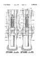
- FIGS. 1A and 1B show a first embodiment of the early evaluation system with pump of the present invention in which a formation pump may be actuated by rotation of the tubing string to draw formation fluid into a chamber containing fluid samplers and instrumentation.
- this first embodiment is shown as it is run into the wellbore, and
- FIG. 1B illustrates the apparatus in operation with the packers inflated.
- FIGS. 2A and 2B show another embodiment of the present invention in which a hydraulic or mud motor is used to actuate the formation pump by pumping mud down the tubing string.
- FIG. 2A illustrates this embodiment as it is run into the wellbore, and FIG. 2B shows it in operation.
- FIGS. 3A and 3B illustrate an embodiment of the invention utilized as part of a drill string by which drilling may be carried out and testing conducted without removal of the drill string.
- FIG. 3A illustrates this embodiment as it is used as a drill string to drill the wellbore
- FIG. 3B illustrates the apparatus in operation during a testing phase.
- FIG. 4 shows an alternate embodiment of the sampling chamber portion of the apparatus.
- FIG. 5 illustrates an alternate embodiment using a reciprocating pump.
- FIG. 6 shows an alternate embodiment with an electric driven pump.
- FIGS. 7A and 7B illustrate an alternate embodiment in which a pump is lowered on a wireline.
- Apparatus 10 is used in a method of servicing a well 12 having an uncased borehole 14 intersecting a subsurface formation or zone of interest 16.
- a reference to a method of servicing a well is used in a broad sense to include both the testing of the well wherein fluids are allowed to flow from the well and the treatment of a well wherein fluids are pumped into the well.
- a reference to a "zone of interest" includes a subsurface formation.
- Apparatus 10 is at the lower end of an outer tubing string 18.
- apparatus 10 includes a straddle packer assembly 20 having upper and lower inflatable packer elements 22 and 24, respectively.
- Packer elements 22 and 24 are adapted to sealingly engage borehole 14 on opposite sides of formation 16 or at desired locations in a zone of interest 16.
- a single element inflatable packer may be used above the formation or in the zone of interest instead of straddle packer assembly 20. That is, the apparatus is not intended to be limited specifically to a straddle packer configuration. Testing with either type of packer is similar.
- a lower housing 26 extends below lower packer element 24.
- an equalizing passage 30 which interconnects a lower equalizing port 32 in lower housing 26 with an upper equalizing port 34 disposed in an upper housing 36.
- Equalizing passage 30 insures that there is essentially the same hydrostatic pressure in upper portion 27 and lower portion 28 of well annulus 29, above upper packer element 22 and below lower packer element 24, respectively, when the packer elements are inflated.
- the system is pressure balanced, and this equalization of pressure across upper and lower packer elements 22 and 24 eliminates hydraulic forces acting on outer tubing string 18 and packer 20.
- An inflation passage 38 extends longitudinally through upper housing 36 and is in communication with upper and lower packer elements 22 and 24 at points 40 and 42, respectively.
- a packer control valve 44 which allows inflation of upper and lower packer elements 22 and 24 by pumping fluid down the inside of outer tubing string 18 and preventing overpressure of the packer elements.
- a sampling chamber 46 is defined in upper housing 36.
- a sampling tube 48 extends from sampling chamber 46 to a plurality of radially disposed sampling ports 50 which are disposed between upper and lower packer elements 22 and 24.
- Sampling chamber 46 may be said to be simply an enlarged upper portion of sampling tube 48 in the embodiment of FIGS. 1A and 1B.
- sampling chamber 46 Disposed in sampling chamber 46 are a plurality of independently activated samplers 52 and any desired electronic or mechanical pressure and temperature recording instruments 53, also called recorders 53.
- Samplers 52 may be similar to the Halliburton Mini-samplers, and pressure and temperature recording instruments 53 may be similar to the Halliburton HMR. Examples of Mini-samplers are shown in U.S. Pat. Nos. 5,240,072; 5,058,674; 4,903,765; and 4,787,447, copies of which are incorporated herein by reference.
- An electronic memory recording fluid resistivity tool such as manufactured by Sondex or Madden, may also be placed in sampling chamber 46. Samplers 52 and instruments 53 are in communication with sampling tube 48 through sampling chamber 46 in the embodiments shown in FIGS. 1A and 1B.
- FIG. 4 An alternate embodiment is shown in FIG. 4.
- the apparatus has an upper housing 36' defining a cavity 55 therein.
- a sampling tube 48' extends through cavity 55 but is not actually in fluid communication therewith.
- a plurality of connections, such as 57 and 59 connect sampling tube 48' to samplers 52' and recorders 53'.
- samplers 52' and recorders 53' are shown disposed in cavity 55, but the invention is not intended to be limited to this particular configuration.
- samplers 52' and 53' could be disposed outside of upper housing 36' and connected to sampling tube 48' directly. In such an embodiment, it would not be necessary to have a cavity 55 at all.
- valve 51 may be disposed in sampling tube 48 or 48'. This is shown in FIGS. 1A and 1B but is omitted from FIG. 4. Valve 51 is normally open, but may be closed during a procedure for performing a bubble point calculation, as will be further described herein. In most of the testing using apparatus 10 or 10', however, valve 51 is either fully opened or not present at all.
- formation pump 54 Disposed above sampling chamber 46 is a formation pump 54 which is used to flow fluid from zone 16 through sampling ports 50 and sampling tube 48 to samplers 52 and recorders 53 in chamber 46 (or to samplers 52' and recorders 53').
- formation pump 54 is a rotary, progressive cavity pump, commonly referred to as a Moineau or Moyno pump.
- This type of pump is well known in the art and generally comprises an elastomeric stator 56 with a rotor 58 rotatably disposed therein. The thread-like configuration of rotor 58 in conjunction with stator 56 allows fluid to be pulled upwardly therethrough.
- Rotor 58 is connected by a flexible shaft portion 60 to a lower end 62 of outer tubing string 18. As outer tubing string 18 is rotated, shaft portion 60 and rotor 58 are also rotated. Shaft portion 60 must be flexible or some other sort of flexible connection must be used because the center line of rotor 58 moves with respect to the center line of apparatus 10, which is an inherent feature of a progressive cavity pump. That is, rotor 58 wobbles somewhat with respect to stator 56, and thus, a flexible connection is necessary.
- packer elements 22 and 24 when packer elements 22 and 24 are inflated, they provide resistance to rotation of upper housing 36 and stator 56.
- a bearing means 64 also provides a rotatable connection between lower end 62 and upper housing 36.
- An annulus 66 is defined around shaft portion 60 in upper housing 36 above stator 56. Communication is provided between annulus 66 and central opening 68 in outer tubing string 18 by a plurality of ports 70.
- a longitudinal passage 72 extends through shaft portion 60 and rotor 58 and provides communication between sampling tube 48 and central opening 68. In fact, longitudinal passage 72 may be considered a portion of sampling tube 48.
- valve 77 is disposed in receptacle 74. In its normally closed position, valve 77 will be seen to close off the upper end of longitudinal passage 72. As will be further described herein, valve 77 is adapted to be opened by an inner well tool.
- Apparatus 10 is run into well 12 to the desired depth on the end of outer tubing string 18 as seen in FIG. 1A. Fluid is pumped down central opening 68 through ports 70 and into annulus 66. The fluid exits annulus 66 and passes through packer control valve 44 and into inflation passage 38 to inflate packer elements 22 and 24 in a manner known in the art to the position shown in FIG. 1B in which the packer elements are sealingly engaged with borehole 14 on opposite sides of formation 16 or at the desired locations in zone 16.
- packer control valve 44 closes to prevent over-inflation of the packer elements, and outer tubing string 18 is rotated at the surface. As previously described, this rotates rotor 58 of pump 54 within stator 56. Rotation of packer assembly 20 and upper housing 36 is prevented by the inflated engagement of packer elements 22 and 24 with borehole 14.
- pump 54 draws fluid from formation or zone 16 through sampling ports 50 and sampling tube 48. This fluid is discharged from pump 54 through annulus 66 and longitudinal passage 70 into central opening 68. Pump 54 is actuated in this manner for a predetermined period of time in order to draw down zone 16.
- the flow from zone 16 should displace fluid standing in central opening 68 of outer housing 18, and a good estimate of the production rate from the zone should be available by monitoring the flow rate at the surface. It is possible to control the production rate by varying the rotation of outer tubing string 18 at the surface.
- the rate of flow through pump 54 varies directly with the rotational speed thereof.
- sampling tube 48 may be sent to the surface via a telemetry system (not shown). These quantities can be observed to determine if the fluid in sampling tube 48 is free of contamination by a mud filtrate. By observing the temperature of the sampling fluid, evidence of flashing the formation fluid is seen as a sudden decrease of temperature.
- one of samplers 52 may be activated and a sample of the fluid in sampling tube 48 taken by flowing into the sampler 52. Operation of any sampler 52 is optional.
- the measurement of zone pressures by recorders 53 may be carried out without capturing any sample if desired.
- Rotation is halted, which ends the operation of pump 54, and the flow of fluid from zone 16 is accordingly stopped. At this point, zone 16 is "shut in.” This build-up phase may be maintained for another predetermined period of time. Samples may be taken in additional samplers 52 and measurements recorded in additional recorders 53 during one of these draw-down/build-up sequences as previously mentioned.
- a secondary or inner well tool 78 has been lowered into engagement with outer tubing string 18 until a stinger element 80 thereof is closely received within seal bore 76 of receptacle 74.
- Inner well tool 78 may be dropped by gravity, pumped down, or conveyed on slick or electric wireline 82 or coiled tubing 84 (shown in phantom lines in FIG. 1B) or on smaller joints of tubing or pipe.
- Potential inner well tools 78 which may be carried by gravity or pumped down include: wireline, coiled tubing or drill pipe retrievable samplers; wireline, coiled tubing or drill pipe retrievable electronic or mechanical pressure/temperature recorders; fluid chambers which may contain chemicals to be injected into zone 16; and a sub which simply opens valve 77 in receptacle 74 so that zone 16 may be in communication with the tubing.
- Potential inner well tools 78 which may be carried by a coiled tubing or slickline include those tools just mentioned.
- Potential secondary tools which may be carried by electric line include those listed above plus instruments for real time surface read-out pressure/temperature and/or fluid properties.
- Inner well tool 78 opens valve 77 in receptacle 74 and thus makes an isolated hydraulic connection between inner well tool 78 and zone 16.
- inner well tool 78 is a surge chamber which may be used to collect a fluid sample from zone 16 which can then be collected by retrieving the surge chamber with wireline 82 or coiled tubing 84.
- inner well tool 78 may also be a pressurized fluid injection canister which is adapted for injecting a treatment fluid into zone 16 through longitudinal passageway 72 and sampling tube 48.
- fluid from zone 16 can be flowed upwardly through the coiled tubing string to a surface location. Also, treatment fluids can be pumped down through coiled tubing 84 or a similar joint of tubing or pipe into zone 16.
- samplers 52, 52' and recorders 53, 53' are removed from sampling chamber 46. Samplers 52, 52' may be drained on location, their contents may be transferred to sample bottles for shipment to a pressure-volume-test (PVT) laboratory, or the entire sampler 52, 52' may be shipped to a PVT laboratory for fluid transfer and testing.
- PVT pressure-volume-test
- Memory gauges and recorders 53, 53' can be read, and the pressure, temperature and resistivity data analyzed to determine formation or zone pressure and temperature, permeability, and sample fluid resistivity.
- a change in sample fluid resistivity during each draw-down phase of the job indicates that the mud filtrate was removed from zone 16 and that fluid pumped through apparatus 10 near the end of the draw-down that was captured in sampler 52, 52' is a representative fluid in the zone.
- a significant change in fluid temperature during the draw-downs would indicate that gas dissolved in the formation fluid came out of solution and flashed to vapor during the draw-down and/or during sampling.
- a determination of the bubble point of the well fluid may be carried out.
- pump 54 is actuated by rotating outer tubing string 18, in the manner previously described, and the pump is run long enough to get formation fluid inside sampling tube 48 and sampling chamber 46 (or in sampling tube 48' in embodiment 10').
- valve 51 is closed to trap a volume of fluid between the valve and pump 54.
- Pump 54 is then operated to reduce the pressure of the trapped fluid sample. As the pressure is decreased inside the trapped volume of fluid, eventually the pressure will drop below the bubble point of the oil contained in the trapped volume of fluid.
- second embodiment 100 may be used in a method of servicing a well 12 having an uncased borehole 14 intersecting a subsurface formation or zone 16.
- second embodiment apparatus 100 actuates a pump therein by hydraulic actuation means such as a hydraulic or mud motor 144 rather than by rotation of the tubing string as in first embodiment apparatus 10.
- hydraulic actuation means such as a hydraulic or mud motor 144
- Apparatus 100 is at the lower end of an outer tubing string 102.
- apparatus 100 includes a straddle packer assembly 104 having upper and lower inflatable packer elements 106 and 108, respectively.
- Packer elements 106 and 108 are adapted to sealingly engage borehole 14 on opposite sides of formation 16 or at desired locations in a zone of interest 16.
- a single inflatable packer may be used above the formation or zone instead of straddle packer assembly 104. That is, apparatus 100 is not intended to be limited specifically to a straddle packer configuration. Testing with either type of packer is similar.
- a lower housing 110 extends below lower packer element 108.
- an equalizing passage 114 which interconnects a lower equalizing port 116 in lower housing 110 with an upper equalizing port 118 in an upper housing 120.
- Equalizing passage 114 insures that there is essentially the same hydrostatic pressure in upper portion 111 and lower portion 112 of well annulus 113 above upper packer element 106 and below lower packer element 108, respectively, when the packer elements are inflated.
- the system is pressure-balanced, and this equalization of pressure across upper and lower packer elements 106 and 108 eliminates hydraulic forces acting on outer tubing string 102 and packer 104.
- An inflation passage 122 extends longitudinally through upper housing 120 and is in communication with upper and lower packer elements 106 and 108 at points 124 and 126, respectively.
- a packer control valve 128 At the upper end of inflation passage 122 is a packer control valve 128 which allows inflation of upper and lower packer elements 106 and 108 by pumping fluid down the inside of outer tubing string 102 and preventing overpressure of the packer elements.
- a sampling chamber 130 is defined in upper housing 120.
- a sampling tube 132 extends from sampling chamber 130 to a plurality of radially disposed sampling ports 134 which are disposed between upper and lower packer elements 106 and 108.
- Sampling chamber 130 may be said to be simply an enlarged upper portion of sampling tube 132 in the embodiment of FIGS. 2A and 2B.
- samplers 136 and instruments 137 Disposed in sampling chamber 130 are a plurality of independently activated samplers 136 and any desired electronic or mechanical pressure and temperature recording instruments 137, also referred to as recorders 137.
- samplers 136 in the second embodiment may be similar to Halliburton Mini-Samplers, and the pressure and electronic pressure and temperature recording instruments 137 may be similar to the Halliburton HMR.
- An electronic memory recording fluid resistivity tool such as manufactured by Sondex or Madden, may also be placed in sampling chamber 130.
- Samplers 136 and instruments 137 are in communication with sampling tube 132 through sampling chamber 130 in the embodiments shown in FIGS. 2A and 2B.
- FIG. 4 An alternate embodiment is shown in FIG. 4.
- the apparatus has an upper housing 120' defining a cavity 55 therein.
- a sampling tube 132' extends through cavity 55 but is not actually in fluid communication therewith.
- a plurality of independently activated samplers 136' and any desired pressure and temperature recording instruments 137', also called recorders 137', are disposed around and adjacent to sampling tube 132'. Samplers 136' and recorders 137' are also not in communication with cavity 55.
- a plurality of connections, such as 57 and 59 connect sampling tube 132' to samplers 136' and recorders 137'.
- samplers 136' and recorders 137' are shown disposed in cavity 55, but the invention is not intended to be limited to this particular configuration.
- samplers 136' and 137' could be disposed outside of upper housing 120' and connected to sampling tube 132' directly. In such an embodiment, it would not be necessary to have a cavity 55 at all.
- valve 135 may be positioned in sampling tube 132 or 132'. This is shown in FIGS. 2A and 2B but omitted from FIG. 4. Valve 135 is normally open, but may be used to perform a bubble point calculation as with valve 51 in the first embodiment.
- a formation pump 138 Disposed above sampling chamber 130 is a formation pump 138 which is used to flow fluid from zone 16 through sampling ports 134 and sampling tube 132 to samplers 136 and recorders 137 in chamber 130 (or to samplers 136' and recorders 137').
- formation pump 138 is a rotary, progressive cavity pump, commonly referred to as a Moineau or Moyno pump, just as in first embodiment 10.
- Pump 138 generally comprises an elastomeric pump stator 140 with a pump rotor 142 rotatably disposed therein. The thread-like configuration of pump rotor 142 in conjunction with pump stator 140 allows fluid to be pulled upwardly therethrough.
- motor 144 Located above pump 138 is a hydraulic motor 144 which may also be referred to as a mud motor 144.
- motor 144 is a rotary, progressive cavity device (Moineau or Moyno) similar to formation pump 138.
- Motor 144 is of a configuration known in the art and generally comprises an elastomeric motor stator 146 with a motor rotor 148 rotatably disposed therein.
- Motor rotor 148 is connected to pump rotor 142 by a flexible shaft portion 150.
- pump rotor 142, shaft portion 150 and motor rotor 148 are shown as a single piece, but multiple-piece construction may be used so long as the components rotate together.
- the thread-like configuration of motor rotor 148 in conjunction with motor stator 146 causes the motor rotor to rotate as fluid is pumped downwardly through outer tubing string 102, as will be further discussed herein.
- Upper housing 120 defines an annular cavity 152 therein through which shaft portion 150 extends.
- a housing port 154 is defined transversely through upper housing 120 and provides communication between annular cavity 152 and well annulus 113.
- Motor rotor 148 is connected by a flexible shaft portion 158 to a receptacle 160.
- Shaft portions 150 and 158 must be flexible or some other sort of flexible connection must be used because the center lines of pump rotor 142 and motor rotor 148 move with respect to the center line of apparatus 100, which is an inherent feature of a progressive cavity pump or motor. That is, pump rotor 142 wobbles somewhat with respect to pump stator 140, and motor rotor 148 wobbles somewhat with respect to motor stator 146. Thus, a flexible connection is necessary.
- Pump 138 and hydraulic motor 144 are supported against longitudinal movement as a result of pressure acting thereon by a thrust bearing 161 which is mounted on a flange 163 and engaged by receptacle 160.
- Flange 161 defines an opening 165 therethrough so that fluid may flow past the flange.
- Receptacle 160 defines a seal bore 162 therein.
- a normally closed valve 173 is disposed in receptacle 160. As will be further described herein, valve 173 is adapted to be opened by an inner well tool.
- longitudinal passage 164 provides communication between seal bore 162 and sampling chamber 130.
- valve 173 will be seen to close off the upper end of longitudinal passage 164.
- Longitudinal passage 164 may be considered a portion of sampling tube 132.
- a telemetry system 166 including a mud pulser unit is disposed above hydraulic motor 144.
- This telemetry system 166 is of a kind known in the art, such as the Halliburton Measurement While Drilling (MWD) or Logging While Drilling (LWD) telemetry systems.
- the purpose of system 166 is to send measured data from apparatus 100 to the surface in real time while circulating fluid or while running pump 138 which draws down the well.
- the telemetry system 166 makes it possible to make gamma and resistivity measurements in real time as apparatus 100 is run into well 12. This allows correlation of packer depth without the need of an electric wireline.
- Telemetry 166 is required in second embodiment 100 because the fluid is discharged from pump 138 into well annul us 113 a s further described herein. That is, the fluid discharged from pump 138 is not pumped into outer tubing string 102 where the volume thereof is known as it is when pumped into outer tubing string 18 of first embodiment 10. Telemetry 166 may be used with first embodiment 10 if desired, but it is not necessary.
- Outer tubing string 102 defines a central opening 168 therethrough which is in communication with hydraulic motor 144 through opening 165 in flange 163 and an annular volume 170 generally defined around shaft portion 158.
- Packer control valve 128 is also in communication with annular volume 170.
- Apparatus 100 is run into well 12 to the desired depth on the end of outer tubing string 102 as seen in FIG. 2A. As packer assembly 104 nears the desired setting depth, circulation is started so that telemetry system 166 can send correlation data to the surface with the mud pulser.
- packer elements 106 and 108 When apparatus 100 is on depth, additional pressure is applied down the tubing to inflate packer elements 106 and 108. Fluid is pumped down central opening 168 through opening 165 and annular volume 170, then passes through packer control valve 128 into inflation passage 122. Packer elements 106 and 108 are inflated to the position shown in FIG. 2B in which the packer elements are sealingly engaged with borehole 14 on opposite sides of formation 16 or at the desired locations in zone 16.
- packer control valve 128 closes to prevent over-inflation of the packer elements.
- pump 138 draws fluid from formation or zone 16 through sampling ports 134 and sampling tube 132. This fluid is discharged from pump 138 through annular cavity 152 and housing port 154 into well annulus 113. Pump 138 is actuated for a period of time in order to draw down zone 16. It is possible to control the formation or zone fluid production rate by controlling the circulation rate through central opening 168 from the surface. The pumping flow rate varies directly with the circulation rate since the circulated fluid is what drives hydraulic motor 144.
- measurements of the physical properties of the fluid produced from zone 16 such as pressure, temperature, density, resistivity, conductivity, dielectric constant or other measurable physical fluid property can be used to determine if the fluid produced from zone 16 contains gas.
- gas is present in the fluid produced from zone 16
- pumping performed on the zone of interest and the resulting commingling of fluid from the zone with the mud in annulus portion 111 above packer 104 should be limited. This is necessary because, as the commingled gas and mud circulate toward the surface, the gas in this mixture will expand. If a large quantity of gas is present in the fluid from zone 16, this may result in a significant decrease in the hydrostatic pressure of the column of fluid in annulus 113 and may result in a well control problem.
- Measurements of the physical properties of the fluid produced from zone 16 can be sent to the surface in real time by telemetry system 166. With knowledge of these parameters, an operator at the surface may determine that gas is present and may stop or limit operation of pump 138. Alternatively, apparatus 100 may also contain sufficient downhole computer processing power to observe the physical properties the fluid from zone 16, make the determination that gas is present, and transmit an alarm to the surface via telemetry system 166.
- one of samplers 136 may be activated in order to take a sample of the fluid in sampling tube 132.
- the operation of this sampler 136 may be initiated by modulating the mud pumps at the surface as a down link command. Operation of any sampler 136 is optional.
- the measurement of zone pressures with recorders 137 without capturing a sample may be desired.
- samples may be taken in additional samplers 136, 136' and measurements recorded in additional recorders 137, 137' during one of these draw-down/build-up sequences as previously mentioned.
- mud pumps at the surface can be used to send a command to apparatus 100 to stop formation pump 138 and start the build-up while maintaining circulation.
- real time build-up pressure is sent to the surface via telemetry.
- Receptacle 160 provides a means of connecting a secondary or inner well tool 172 which may be lowered down to apparatus 100 through outer tubing string 102 until a stinger element 171 thereof is closely received within seal bore 162 of receptacle 160. This. places inner well tool 172 in fluid communication with zone 16 through sampling tube 132 and longitudinal passage 164 by opening the closed valve 173 in receptacle 160.
- Inner well tool 172 like inner well tool 78 of the first embodiment, may be dropped by gravity, pumped down, or conveyed on a slickline or wireline 174 or a coiled tubing string 176 or smaller joints of tubing or pipe, as seen in FIG. 2B.
- Inner well tool 172 can be used to open valve 173 in receptacle 160 to make an isolated hydraulic connection between inner well tool 172 and formation 16.
- Potential inner well tools 172 which may be carried by gravity or pumped down include: wireline, coiled tubing or drill pipe retrievable samplers; wireline, coiled tubing or drill pipe retrievable electronic or mechanical pressure/temperature recorders; fluid chambers which may contain chemicals to be injected into zone 16; and a sub which simply opens valve 173 in receptacle 172 so that zone 16 may be in fluid communication with outer tubing string 102.
- Potential inner well tools 172 which may be carried by coiled tubing or slick line include any of those listed above.
- Potential inner well tools 172 which may be carried by electric line include those listed above plus instruments for real time surface readout pressure/temperature and/or fluid properties.
- inner well tool 172 Preferred embodiments of inner well tool 172 are the same as those described for inner well tool 78 of first embodiment apparatus 10.
- apparatus 100 is retrieved to the surface. There, samplers 136, 136' and recording instruments 137, 137' are removed from sampling chamber 130. Samplers 136, 136' may be drained on location, their contents may be transferred to sample bottles for shipment to a PVT laboratory, or the entire sampler 136, 136' may be shipped to a PVT laboratory for fluid transfer and testing.
- the memory gauges in instruments 137, 137' can be read, and the pressure, temperature and resistivity data can be analyzed to determine formation pressure and temperature, permeability, and sample fluid resistivity.
- a change in sample fluid resistivity during each draw-down phase of the job would indicate that the mud filtrate was removed from zone 16 and that the fluid pumped through apparatus 100 near the end of the draw-down that was captured in the activated sampler 136, 136' is a representative fluid in the zone.
- a significant change in fluid temperature during the draw-downs would indicate that gas dissolved in the formation fluid came out of solution and flashed to vapor during the draw-down and/or during sampling.
- a calculation of the bubble point of the well fluid may be carried out.
- pump 138 With the apparatus positioned in wellbore 14 as shown in FIG. 2B, pump 138 is actuated in the manner previously described, and the pump is run long enough to get formation fluid inside sampling tube 132 and sampling chamber 130 (or in sampling tube 132' in embodiment 100'). With formation fluid thus inside the tool, valve 135 is closed to trap a volume of fluid between the valve and pump 138. Pump 138 is then operated to reduce the pressure of the trapped fluid sample. As the pressure is decreased inside the trapped volume of fluid, eventually the pressure will drop below the bubble point of the oil contained in the trapped volume of fluid.
- FIGS. 3A and 3B A third embodiment of the early evaluation system with pump of the present invention is shown in FIGS. 3A and 3B and generally designated by the numeral 200.
- Apparatus 200 like the first and second embodiments, is used in a method of drilling and servicing a well 12 having an uncased borehole 14 intersecting a subsurface formation or zone 16. However, apparatus 200 is also incorporated into a drill string so that such servicing can be carried out without removing the drill string from well 12.
- Apparatus 200 is at the lower end of an outer drilling string 202 which may also be referred to as a tubing string 202.
- apparatus 200 includes a straddle packer assembly 204 having upper and lower inflatable packer elements 206 and 208, respectively.
- Packer elements 206 and 208 are adapted to sealingly engage borehole 14 on opposite sides of formation 16 or at desired locations in a zone of interest 16.
- a single element inflatable packer may be used above the formation or zone instead of straddle packer assembly 204. That is, as with the other embodiments, apparatus 200 is not intended to be limited specifically to a straddle packer configuration. Testing with either packer is similar.
- a lower housing 210 extends below lower packer element 208.
- a drill bit 212 of a kind known in the art, which is used to drill borehole 14 by rotation of outer tubing string 202.
- a tube or passageway 213 extends through lower housing 210 and opens at its lower end adjacent to drill bit 212. As will be further described, tube 213 allows drilling fluid to be pumped to drill bit 212 during a drilling operation.
- Equalizing passage 214 insures that there is essentially the same hydrostatic pressure in upper portion 221 and lower portion 223 of well annulus 225, above upper packer element 206 and below lower packer element 208, respectively, when the packer elements are inflated.
- the system is pressure-balanced, and this equalization of pressure across upper and lower packer elements 206 and 208 eliminates hydraulic forces acting on outer tubing string 202 and packer 204.
- An inflation passage 222 extends longitudinally through upper housing 220 and is in communication with upper and lower packer elements 206 and 208 at points 224 and 226, respectively.
- a packer control valve 228 At the upper end of inflation passage 222 is a packer control valve 228 which allows inflation of upper and lower packer elements 206 and 208 by pumping fluid down outer tubing string 202 and preventing overpressure of the packer elements.
- a sampling chamber 230 is defined in upper housing 220.
- a sampling tube 232 extends longitudinally from sampling chamber 230.
- Sampling chamber 230 may be said to be simply an enlarged upper portion of sampling tube 232 in the embodiment of FIGS. 3A and 3B.
- samplers 234 Disposed in sampling chamber 230 are a plurality of independently activated samplers 234 and any desired electronic or mechanical pressure and temperature recording instruments 235, also called recorders 235.
- samplers 234 in the third embodiment may be similar to Halliburton Mini-Samplers, and pressure and temperature recording instruments 235 may be similar to the Halliburton HMR.
- An electronic memory recording resistivity tool such as manufactured by Sondex or Madden, may also be placed in sampling chamber 230.
- Samplers 234 and instruments 235 are in communication with sampling tube 232 through sampling chamber 230 in the embodiments shown in FIGS. 3A and 3B.
- FIG. 4 An alternate embodiment is shown in FIG. 4.
- the apparatus has an upper housing 220' defining a cavity 55 therein.
- a sampling tube 232' extends through cavity 55 but is not actually in fluid communication therewith.
- a plurality of independently activated samplers 234' and any desired pressure and temperature recording instruments 235', also called recorders 235', are disposed around and adjacent to sampling tube 232'. Samplers 234' and recorders 235' are also not in communication with cavity 55.
- a plurality of connections, such as 57 and 59 connect sampling tube 232' to samplers 234' and recorders 235'.
- samplers 234' and recorders 235' are shown disposed in cavity 55, but the invention is not intended to be limited to this particular configuration.
- samplers 234' and 235' could be disposed outside of upper housing 220' and connected to sampling tube 232' directly. In such an embodiment, it would not be necessary to have a cavity 55 at all.
- an optional valve 233 may be positioned in sampling tube 232 or 232'. This is shown in FIGS. 3A and 3B but omitted from FIG. 4. Valve 233 is normally open, but may be closed to perform a bubble point calculation as previously described for the first embodiment.
- a lower circulating valve 236 is disposed in packer 204 between packer elements 206 and 208.
- Lower circulating valve 236 may be actuated between a first, drilling position shown in FIG. 3A and a second, formation evaluation or test position shown in FIG. 3B.
- lower circulating valve 236 places sampling tube 232 in communication with tube 213 so that drilling fluid may be pumped through packer 204 to drill bit 212, as will be further described herein.
- lower circulating valve 236 closes communication between sampling tube 232 and tube 213 and places the sampling tube in communication with a plurality of radially disposed sampling ports 238 between packer elements 206 and 208.
- sampling ports 238 are in communication with sampling chamber 230.
- a formation pump 240 Disposed above sampling chamber 230 is a formation pump 240 which is used to flow fluid from zone 16 through sampling ports 238 and sampling tube 232 to samplers 234 and recorders 235 in chamber 230 when lower circulating valve 236 is in the evaluation position (or to samplers 234' and recorders 235').
- formation pump 240 is a rotary, progressive cavity pump, commonly referred to as a Moineau or Moyno pump just as in first embodiment 10 and second embodiment 100.
- Pump 240 generally comprises an elastomeric pump stator 242 with a pump rotor 244 rotatably disposed therein. The thread-like configuration of pump rotor 244 in conjunction with pump stator 242 allows fluid to be pulled upwardly therethrough.
- motor 246 In a manner similar to second embodiment 100, located above pump 240 is a hydraulic motor 246 which may also be referred to as a mud motor 246.
- motor 246 is a rotary, progressive cavity device (Moineau or Moyno) similar to formation pump 240.
- Motor 246 is of a configuration known in the art and generally comprises an elastomeric motor stator 248 with a motor rotor 250 rotatably disposed therein.
- Motor rotor 250 is connected to pump rotor 244 by a flexible shaft portion 252.
- pump rotor 244, shaft portion 252 and motor rotor 250 are shown as a single piece, but multiple-piece construction may be used so long as the components rotate together.
- the thread-like configuration of motor rotor 250 in conjunction with motor stator 248 causes the motor rotor to rotate as fluid is pumped downwardly through outer tubing string 202, as will be further discussed herein.
- Upper housing 220 defines an annular cavity 254 therein through which shaft portion 252 extends.
- a housing port 256 is defined transversely through upper housing 220 and provides communication between annular cavity 254 and well annulus 225.
- Motor rotor 250 is connected by a flexible shaft portion 260 to a receptacle 262.
- Shaft portions 252 and 260 must be flexible or some other sort of flexible connection must be used because the center lines of pump rotor 244 and motor rotor 250 move with respect to the center line of apparatus 200, which is an inherent feature of a progressive cavity pump or motor. That is, pump rotor 244 wobbles somewhat with respect to pump stator 242, and motor rotor 250 wobbles somewhat with respect to motor stator 248. Thus, a flexible connection is necessary.
- Pump 240 and hydraulic motor 246 are supported against longitudinal movement as a result of pressure acting thereon by a thrust bearing 261 which is mounted on a flange 263 and engaged by receptacle 263.
- Flange 265 defines an opening 267 therethrough which allows fluid flow past the flange.
- Receptacle 262 defines a seal bore 264 therein.
- a normally closed valve 265 is disposed in receptacle 262.
- An upper circulating valve 266 is positioned in or adjacent to shaft portion 260.
- Receptacle 262 and an upper end of shaft portion 260 define an upper portion 268 of a longitudinal passage 270 above upper circulating valve 266. In its normally closed position, valve 265 will be seen to close off the upper end of longitudinal passage 270.
- a lower end of shaft portion 260, motor rotor 250, shaft portion 252 and pump rotor 244 define a lower portion 272 of longitudinal passage 270 below lower circulating valve 266.
- Telemetry 280 is required in third embodiment 200 because the fluid is discharged from pump 240 into well annulus 225. That is, the fluid discharged from pump 240 is not pumped into outer tubing string 202 where the volume thereof is known as it is when pumped into outer tubing string 18 of first embodiment 10.
- Outer tubing string 202 defines a central opening 274 therethrough which is in communication with upper circulating valve 266 and with hydraulic motor 246 through opening 267 in flange 265 and an annular volume 276 generally defined around shaft portion 260.
- Packer control valve 228 is also in communication with annular volume 276.
- Upper circulating valve 266 has a first, drilling position shown in FIG. 3A and a second, formation evaluation or test position shown in FIG. 3B.
- a port 278 in upper circulating valve 266 is open so that annular volume 276 is in communication with longitudinal passage 270.
- upper circulating valve 266 is closed so that longitudinal passage 270 is isolated from annular volume 276 while upper portion 268 and lower portion 272 of longitudinal passage 270 are in communication with one another.
- the drilling position of upper circulating valve 266 corresponds to the drilling position of lower circulating valve 236, and similarly, the formation evaluation position of upper circulating valve 266 corresponds to the formation evaluation position of lower circulating valve 236.
- central opening 274 of outer tubing string 202 is in communication with drill bit 212 so that drilling fluid or mud may be pumped downwardly through apparatus 200 during drilling operations.
- communication is provided between seal bore 264 and sampling chamber 230, and the sampling chamber is further in communication with sampling ports 238.
- a telemetry system 280 including a mud pulser unit is disposed above hydraulic motor 246.
- the telemetry system 280 is of a kind known in the art, such as the Halliburton MWD or LWD telemetry systems, such as previously described with regard to second embodiment 100.
- the purpose of system 280 is to send measured data from apparatus 200 to the surface in real time while circulating fluid, while running pump 240 which draws down the well, or while drilling.
- the telemetry system 280 makes it possible to make gamma and resistivity measurements in real time as apparatus 200 is used to drill well 12. This allows correlation of packer depth without the need of an electric wireline.
- Apparatus 200 is initially configured as shown in FIG. 3A with upper and lower circulating valves 266 and 236 in their first or drilling positions. Normally, well 12 has already been started, and apparatus 200 is positioned so that drill bit 212 is adjacent to the bottom of the well. The entire tool string is rotated so that drill bit 212 cuts borehole 14 of well 12 further. Drilling is performed in the usual manner for rotary rigs. Drilling fluid is pumped down central opening 274 through annular volume 276, open valve port 278 in upper circulating valve 266, lower portion 272 of longitudinal passage 270, sampling tube 232, lower circulating valve 236 and tube 213 to be discharged adjacent to drill bit 212. The fluid is circulated back up well annulus 225 in a conventional manner as well 12 is drilled. During the drilling operation, telemetry system 280 can send logging information to the surface with the mud pulser.
- upper and lower circulating valves 266 and 236 are actuated to their second or formation evaluation positions. For example, if upper and lower circulating valves 266 and 236 are pressure actuated, a down link command is sent to the valves to actuate them to their second positions. As previously discussed, the actuation of upper circulating valve 266 closes valve port 278.
- the operation of upper and lower circulating valves 266 and 236 may be coordinated with the operation of packer control valve 228.
- Packer elements 206 and 208 are inflated to the position shown in FIG. 3B in which the packer elements are sealingly engaged with borehole 14 on opposite sides of formation 16 or at the desired locations in zone 16.
- packer control valve 228 closes to prevent over-inflation of the packer elements.
- pump 240 draws fluid from formation or zone 16 through sampling ports 238 and sampling tube 232. This fluid is discharged from pump 240 through annular cavity 254 and housing port 256 into well annulus 225. Pump 240 is actuated for a period of time in order to draw down zone 16. It is possible to control the formation or zone fluid production rate by controlling the circulating rate through central opening 274 from the surface. The pumping flow rate varies directly with the circulation rate since the circulated fluid is what drives hydraulic motor 246.
- measurements of the physical properties of the fluid produced from zone 16 such as pressure, temperature, density, resistivity, conductivity, dielectric constant or other measureable physical fluid property can be used to determine if the fluid produced from zone 16 contains gas.
- gas is present in the fluid produced from zone 16
- pumping performed on the zone of interest and the resulting commingling of fluid from the zone of interest with the mud in annulus portion 221 above packer 204 should be limited. This is necessary, because, as the commingled gas and mud circulate toward the surface, the gas in this mixture will expand. If a large quantity of gas is present in the fluid from zone 16, this may result in a significant decrease in the hydrostatic pressure of the column of fluid in annulus 225 and may result in a well control problem.
- Measurements of the physical properties of the fluid produced from zone 16 can be sent to the surface in real time by telemetry system 280. With knowledge of these parameters, an operator at the surface may determine that gas is present and may stop or limit the operation of pump 240. Alternatively, apparatus 200 may further comprise sufficient downhole computer processing power to observe the physical properties of the fluid from zone 16, make the determination that gas is present, and transmit an alarm to the surface via telemetry system 280.
- one of samplers 234 may be activated in order to take a sample of the fluid in sampling tube 232.
- the operation of this sampler 234 may be initiated by modulating the mud pumps at the surface as a down-link command. Operation of any sampler 234 is optional.
- the measure of zone pressures with recorders 235, 235' without capturing a sample may be desired.
- mud pumps at the surface can be used to send a command to apparatus 200 to stop formation pump 240 and start the build-up while maintaining circulation.
- real time build-up pressure is sent to the surface via telemetry.
- Receptacle 262 also provides a means of connecting a secondary or inner well tool 282, which may be lowered to apparatus 200 through outer tubing string 202 until a stinger element 283 thereof is closely received within seal bore 264 of receptacle 262. This places inner well tool 282 in fluid communication with zone 16 through sampling tube 232 and longitudinal passage 270 by opening the closed valve 265 in receptacle 262.
- Inner well tool 282, like those in embodiments 10 and 100, may be dropped by gravity, pumped down, or conveyed on a slickline or wireline 284 or a coiled tubing string 286 or smaller joints of tubing or pipe, as seen in FIG. 3B.
- Inner well tool 282 can be used to open valve 265 in receptacle 262 to make an isolated hydraulic connection between inner well tool 282 and formation 16.
- Potential inner well tools 282 which may be carried by gravity or pumped down include: wireline, coiled tubing or drill pipe retrievable samplers, wireline, coiled tubing or drill pipe retrievable electronic or mechanical pressure/temperature recorders; fluid chambers which may contain chemicals to be injected into zone 16; and a sub which simply opens receptacle 262 so that zone 16 may be in fluid communication with outer tubing string 202.
- Potential inner well tools 282 which may be carried by coiled tubing or slick line include any of those listed above.
- Potential inner well tools 282 which may be carried by electric line include those listed above plus instruments for real time surface readout pressure/temperature and/or fluid properties.
- inner well tool 282 are the same as those described for inner well tools 78 and 172 of the first and second embodiments.
- apparatus 200 is retrieved to the surface. There, samplers 234, 234' and recording instruments 235, 235' are removed from sampling chamber 230. Samplers 234, 234' may be drained on location, their contents may be transferred to sample bottles for shipment to a PVT laboratory, or the entire sampler 234, 234' may be shipped to a PVT laboratory for fluid transfer and testing.
- the memory gauges and instruments 235, 235' can be read, and the pressure, temperature and resistivity data can be analyzed to determine formation pressure and temperature, permeability, and sample fluid resistivity.
- a change in sample fluid resistivity during each draw-down phase of the job would indicate that the mud filtrate was removed from zone 16 and that the fluid pumped through apparatus 200 near the end of the draw-down that was captured in the activated sampler 234, 234' is a representative fluid in the zone.
- a significant change in fluid temperature during the draw-downs would indicate that gas dissolved in the formation fluid came out of solution and flashed vapor during the draw-down and/or during sampling.
- a calculation of the bubble point of the well fluid may be carried out.
- pump 240 is actuated in the manner previously described, and the pump is run long enough to get formation fluid inside sampling tube 232 and sampling chamber 230 (or in sampling tube 232' in embodiment 200').
- valve 233 is closed to trap a volume of fluid between the valve and pump 240.
- Pump 240 is then operated to reduce the pressure of the trapped fluid sample. As the pressure is decreased inside the trapped volume of fluid, eventually the pressure will drop below the bubble point of the oil contained in the trapped volume of fluid.
- FIGS. 5-7 additional formation pump embodiments for the early evaluation system of the present invention will be discussed.
- the pump is mechanically actuated as opposed to hydraulically actuated.
- Pump 290 comprises a cylinder housing or portion 292 defining a cylinder bore 294 therein and a plunger housing or portion 296 having a plunger 298 extending downwardly therefrom.
- Plunger 298 is connected to an outer tubing string 299 and adapted for reciprocating movement within cylinder bore 294, and sealing engagement is provided therebetween by a sealing means 300.
- a pumping chamber 302 is defined within cylinder bore 294 below plunger 298.
- Cylinder housing 292 extends upwardly from a packer (not shown) similar or identical to those previously discussed, and the cylinder housing defines a sampling chamber 304 below, and in communication with pumping chamber 302.
- a sampling tube 306 extends from sampling chamber 304 to sampling ports between upper and lower packer elements, as previously described.
- samplers 308 and recorders 310 Disposed in sampling chamber 304 are a plurality of independently activated samplers 308 and any desired electronic or mechanical pressure and temperature recording instruments 310, also called recorders 310. Samplers 308 and recorders 310 are the same as those previously described and are used in the same or similar manner. Alternatively, the arrangement shown in FIG. 4 could be incorporated into this embodiment as well.
- Cylinder housing 292 further defines an inflation passage 312 which is in communication with the inflatable elements of the packer.
- inflation passage 312 At the upper end of inflation passage 312 is a packer control valve 314 which allows inflation of the packer elements by pumping fluid down outer tubing string 299 as will be further described herein and preventing overpressure of the packer elements in the same manner as the earlier described embodiments.
- Packer control valve 314 is in communication with a transverse port 315.
- a sealing means such as a pair of seals 317 provide sealing engagement between cylinder housing 292 and plunger 298 on opposite sides of port 315.
- An inlet valve seat 316 is located at the upper end of sampling tube 306, and an inlet valve 318 is disposed adjacent to the inlet valve seat.
- inlet valve 318 is shown as a ball check valve 318 which allows fluid flow upwardly through sampling tube 306, but prevents downward flow therethrough. That is, when inlet valve 318 is closed, communication between sampling chamber 304 and sampling tube 306 is prevented, but when inlet valve 318 is open and moved upwardly with respect to inlet valve seat 316, there is fluid communication between sampling chamber 304 and sampling tube 306.
- a plunger cavity 320 is defined in plunger 298 and is in communication with a central opening 322 in outer tubing string 299.
- An outlet port 324 is defined in the lower end of plunger 298 and is in communication with pumping chamber 302. Above outlet port 324, plunger 298 defines an outlet valve seat 326.
- An outlet valve 328 is positioned adjacent to outlet valve seat 326.
- Outlet valve' 328 is also illustrated as a ball check valve 328 which allows fluid flow upwardly through outlet port 324 while preventing fluid flow downwardly therethrough. That is, when outlet valve 328 is in a closed position, communication between plunger cavity 320 and outlet port 324 is prevented, and when outlet valve 328 is in an open position, as shown in FIG. 5, upward fluid flow from outlet port 324 into plunger cavity 320 is permitted.
- a transverse port 329 is defined in plunger 298 and provides communication between plunger cavity 320 and plunger annulus 331. As will be further described herein, port 329 in plunger 298 is adapted for alignment with port 315 in cylinder housing 292 for packer inflation.
- plunger 298 Extending through plunger 298 is an elongated tubular portion 330 which defines a passage 332 therethrough.
- the lower end of passage 332 is in communication with pumping chamber 302.
- passage 332 opens into a receptacle 334 which defines a seal bore 336 therein.
- a normally closed valve 338 is disposed in seal bore 336 and normally prevents communication between passage 332 and central opening 322 and outer tubing string 299.
- the operation of the early evaluation system with pump 290 is similar to that of first embodiment apparatus 10 except that pump 290 is actuated by reciprocation of tubing string 299 rather than rotation thereof.
- plunger 298 As the apparatus is lowered into the wellbore, the weight of the components from cylinder housing 292 downwardly will cause plunger 298 to be fully retracted with respect to cylinder housing 292. In this position, port 329 in plunger 298 is in alignment with port 315 in cylinder housing 292. Fluid may be pumped downwardly through aligned ports 329 and 315 and thus through packer control valve 314 and inflation passage 312 to inflate the packer.
- plunger 298 is fully raised, the tubing string is then lowered which, of course, results in lowering plunger 298. This reduces the volume of pumping chamber 302. Fluid in pumping chamber 302 is discharged through outlet valve 328 into plunger cavity 320. During this downward stroke, fluid is prevented from entering sampling tube 306 by closed inlet valve 318.
- pump 290 draws fluid from the formation or zone of interest and discharges it into central opening 322 of outer tubing string 299.
- Pump 290 is actuated in this manner for a predetermined period of time in order to draw down the zone.
- the flow from the zone should displace fluid standing in central opening 322, and a good estimate of the production rate from the zone should be available by monitoring the flow rate at the surface. It is possible to control the production rate by varying the reciprocation of the tubing string at the surface.
- the rate of flow through pump 290 varies directly with the reciprocating speed of the tubing string .
- An inner well tool (not shown) of the type previously described may be lowered into central opening 322 of outer tubing string 299 to engage receptacle 334 and thereby open valve 338. This places the inner tubing in communication with passage 332.
- FIG. 6 another alternate embodiment pump is shown and generally designated by the numeral 340.
- Pump 340 is disposed in an upper housing 342 which is connected to a packer (not shown) in the manner previously described.
- upper housing 342 defines a sampling chamber 344 and a sampling tube 346 therein.
- the construction of these portions may be the same as the previous embodiments described, including that in FIG. 4. That is, a plurality of samplers 348 and recorders 350 are in communication with sampling tube 346.
- Pump 340 is again a rotary, progressive cavity pump having an elastomeric stator 352 and a rotor 354 rotatably disposed in the stator.
- rotor 354 is connected to, and driven by, an electric motor 356.
- the connection between electric motor 356 and pump rotor 354 may be made in any manner known in the art, such as by a flexible shaft, coupling, transmission, etc.
- An elongated tubular portion 358 defining a longitudinal passage 360 therein extends upwardly in upper housing 342 above electric motor 356.
- An annulus 362 is defined around a portion of tubular portion 358 and is in communication with a central opening 364 of an outer tubing string 366.
- Outer tubing string 366 is connected to, or forms a part of, upper housing 342.
- passage 360 is in communication with another passage 368 defined through pump rotor 354.
- Passage 368 opens into sampling chamber 344 and is in communication with sampling tube 346.
- passage 360 opens into a receptacle 370 which defines a seal bore 372 therein.
- a normally closed valve 374 is disposed in seal bore 372. When closed, valve 374 prevents communication between passage 360 and central opening 364.
- An outlet port 376 is also defined in upper housing 342 and provides communication between a discharge side of pump 340 and annulus 362.
- FIG. 6 Also shown in FIG. 6 is an inflation passage 378 with a packer control valve 380 at the upper end thereof. Inflation passage 378 and packer control valve 380 are used in the same manner as in the other embodiments.
- the early evaluation system utilizing pump 340 is lowered into the wellbore, and the packer is set in the manner previously described.
- an electric line tool 382 is lowered into central opening 364 of outer tubing string 366 so that it engages seal bore 372 in receptacle 370.
- Electric line tool 382 may also be used to open valve 374 as desired.
- Electric line tool 382 completes an electrical connection to electric motor 356 so that the electric motor can be energized to rotate pump rotor 354 within pump stator 352.
- Pump 340 thus draws fluid from the formation or zone of interest through sampling tube 346 in the previously described manner. This fluid is discharged from pump 340 through outlet port 376 into central opening 364 of outer tubing string 366. Pump 340 is operated in this manner for a predetermined period of time in order to draw down the zone. The flow from the zone should displace fluid standing in central opening 364 of outer tubing string 366, and a good estimate of the production rate from the zone and should be available by monitoring the flow rate at the surface.
- Electric motor 356 may be a variable speed motor so that it is possible to control the production rate by varying the speed of the electric motor. The rate of flow through pump 340 varies directly with the rotational speed of rotor 354.
- FIGS. 7A and 7B a further alternate pump embodiment is shown.
- the pump is not located in a housing portion of the apparatus, but rather is lowered on a wireline to be engaged with a receptacle.
- the apparatus includes an upper housing 384 defining a sampling chamber 386 and a sampling tube 388 therein.
- a plurality of samplers 390 and recorders 392 may be disposed in the apparatus and placed in communication with sampling tube 388.
- the embodiment of FIG. 4 may also be used.
- Upper housing 384 also defines an inflation passage 394 and has a packer control valve 396 disposed therein. Packer control valve 396 and inflation passage 394 are used in the previously described manner to inflate an inflatable packer (not shown) attached to upper housing 384.
- An outer tubing string 398 forms an upper portion of, or is a separate component attached to, upper housing 384.
- Outer tubing string 398 defines a central opening 400 therein.
- Packer control valve 396 is in communication with central opening 400.
- a tubular portion 402 extends upwardly in central opening 400 and defines a passage 404 therein. Passage 404 is in communication with sampling chamber 386 and sampling tube 388.
- Receptacle 406 At the upper end of tubular portion 402 is a receptacle.
- Receptacle 406 As illustrated in FIG. 7A, has a sliding valve sleeve 408 which normally covers a transverse port 410.
- Transverse port 410 is in communication with passage 404 in tubular portion 402.
- a special wireline tool 412 may be lowered on a wireline 414 as seen in FIG. 7A.
- Wireline tool 412 includes a housing 416 defining a cavity 418 therein.
- Housing 416 has an open lower end 420.
- Housing 416 further defines a housing port 422 therein which provides communication between cavity 416 and central opening 400.
- an electric pump 424 Disposed in cavity 418 of housing 416 below housing port 422 is an electric pump 424 which has a downwardly facing inlet side 426 and an upwardly facing discharge side 428 in communication with housing port 422.
- An array of samplers and sensors 430 may also be disposed in housing 416 of wireline tool 412.
- the packer is set in the previously described manner, and wireline tool 412 is lowered into engagement with receptacle 406 as seen in FIG. 7B.
- Housing 416 fits over receptacle 406 so that a portion thereof extends into cavity 418.
- Valve sleeve 408 is moved downwardly to an open position in which transverse port 410 is uncovered and placed in communication with cavity 418 and housing 416.
- pump inlet 426 is in communication with sampling chamber 386 and sampling tube 388 through cavity 418, port 410 and passage 404.
- a sealing means 432 may be used to provide sealing engagement between housing 416 and tubular portion 402 below transverse port 410 when valve sleeve 408 is in the open position shown in FIG. 7B.
- pump 424 is operated to draw fluid from the formation or zone of interest through sampling tube 388. This fluid is discharged from pump 424 through port 422 into central opening 400 of outer tubing string 398. Pump 424 is operated in this manner for a period of time in order to draw down the zone. The flow from the zone should displace fluid standing in central opening 400, and a good estimate of the production rate from the zone should be available by monitoring the flow rate at the surface. If electric pump 424 has a variable speed, the production rate may be controlled by varying the speed of the pump at the surface. The rate of flow through pump 424 would then vary directly with the speed thereof.
- the array of samplers and sensors 430 may be used to provide an indication at the surface of the position of wireline tool 412. Also, additional samples and measurements may be taken utilizing such an array as previously known in the art.
- valves 51, 135 or 233 may be positioned in the corresponding sampling tube. Such a normally opened valve could then be closed as desired to perform a bubble point calculation as previously described for the other embodiments.
Landscapes
- Engineering & Computer Science (AREA)
- Life Sciences & Earth Sciences (AREA)
- Geology (AREA)
- Mining & Mineral Resources (AREA)
- Physics & Mathematics (AREA)
- Environmental & Geological Engineering (AREA)
- Fluid Mechanics (AREA)
- General Life Sciences & Earth Sciences (AREA)
- Geochemistry & Mineralogy (AREA)
- Mechanical Engineering (AREA)
- Sampling And Sample Adjustment (AREA)
- Investigation Of Foundation Soil And Reinforcement Of Foundation Soil By Compacting Or Drainage (AREA)
Priority Applications (1)
| Application Number | Priority Date | Filing Date | Title |
|---|---|---|---|
| US08/941,883 US5799733A (en) | 1995-12-26 | 1997-09-30 | Early evaluation system with pump and method of servicing a well |
Applications Claiming Priority (2)
| Application Number | Priority Date | Filing Date | Title |
|---|---|---|---|
| US57848995A | 1995-12-26 | 1995-12-26 | |
| US08/941,883 US5799733A (en) | 1995-12-26 | 1997-09-30 | Early evaluation system with pump and method of servicing a well |
Related Parent Applications (1)
| Application Number | Title | Priority Date | Filing Date |
|---|---|---|---|
| US57848995A Continuation | 1995-12-26 | 1995-12-26 |
Publications (1)
| Publication Number | Publication Date |
|---|---|
| US5799733A true US5799733A (en) | 1998-09-01 |
Family
ID=24313104
Family Applications (1)
| Application Number | Title | Priority Date | Filing Date |
|---|---|---|---|
| US08/941,883 Expired - Lifetime US5799733A (en) | 1995-12-26 | 1997-09-30 | Early evaluation system with pump and method of servicing a well |
Country Status (6)
| Country | Link |
|---|---|
| US (1) | US5799733A (fr) |
| EP (1) | EP0781893B8 (fr) |
| AU (1) | AU720964B2 (fr) |
| CA (1) | CA2193309C (fr) |
| DE (1) | DE69636665T2 (fr) |
| NO (1) | NO319932B1 (fr) |
Cited By (113)
| Publication number | Priority date | Publication date | Assignee | Title |
|---|---|---|---|---|
| WO1999022114A1 (fr) * | 1997-10-24 | 1999-05-06 | Baird Jeffrey D | Procede et dispositif servant a fermer un puits tout en laissant le train de tiges dans le trou de forage |
| US5963138A (en) * | 1998-02-05 | 1999-10-05 | Baker Hughes Incorporated | Apparatus and method for self adjusting downlink signal communication |
| US6058772A (en) * | 1996-09-03 | 2000-05-09 | Posiva Oy | Sampling device |
| WO2000047870A1 (fr) * | 1999-01-26 | 2000-08-17 | Dybdahl Bjoern | Procede permettant d'effectuer un echantillonnage et/ou une mesure d'ecoulement de fluide a reservoir |
| WO2000065199A1 (fr) * | 1999-04-22 | 2000-11-02 | Schlumberger Technology Corporation | Procede et appareil pour tester en continu un puits de forage |
| EP1096104A1 (fr) * | 1999-10-26 | 2001-05-02 | Halliburton Energy Services, Inc. | Dispositif et procédé d'essai et de forage de puits |
| WO2001027432A3 (fr) * | 1999-10-09 | 2001-10-04 | Schlumberger Ltd | Procedes et appareil pour realiser des mesures sur des fluides produits par des formations souterraines |
| WO2001077489A1 (fr) * | 1999-01-26 | 2001-10-18 | Dybdahl Bjoern | Procede de conduite de mesures in situ de proprietes d'un fluide de gisement |
| US6325146B1 (en) * | 1999-03-31 | 2001-12-04 | Halliburton Energy Services, Inc. | Methods of downhole testing subterranean formations and associated apparatus therefor |
| US6328103B1 (en) | 1999-08-19 | 2001-12-11 | Halliburton Energy Services, Inc. | Methods and apparatus for downhole completion cleanup |
| US6330913B1 (en) | 1999-04-22 | 2001-12-18 | Schlumberger Technology Corporation | Method and apparatus for testing a well |
| US6340062B1 (en) | 2000-01-24 | 2002-01-22 | Halliburton Energy Services, Inc. | Early formation evaluation tool |
| US6357525B1 (en) | 1999-04-22 | 2002-03-19 | Schlumberger Technology Corporation | Method and apparatus for testing a well |
| WO2002035054A1 (fr) * | 2000-10-26 | 2002-05-02 | Halliburton Energy Services, Inc | Procede et appareil d'essai in-situ de puits de production |
| US6382315B1 (en) | 1999-04-22 | 2002-05-07 | Schlumberger Technology Corporation | Method and apparatus for continuously testing a well |
| WO2002063138A1 (fr) * | 2001-02-06 | 2002-08-15 | Weatherford/Lamb, Inc. | Instrument permettant de realiser une diagraphie des puits sur place |
| US6478096B1 (en) * | 2000-07-21 | 2002-11-12 | Baker Hughes Incorporated | Apparatus and method for formation testing while drilling with minimum system volume |
| US20020194907A1 (en) * | 1998-06-15 | 2002-12-26 | Schlumberger Technology Corporation | Method and apparatus for the detection of bubble point pressure |
| US6530428B1 (en) | 2000-10-26 | 2003-03-11 | Halliburton Energy Services, Inc. | Method and apparatus for in-situ production well testing |
| US20030088184A1 (en) * | 2001-10-11 | 2003-05-08 | Kelly Clifford Mark | System for processing signal data representing physiological parameters |
| WO2003042496A1 (fr) * | 2001-11-15 | 2003-05-22 | Bp Exploration Operating Company Limited | Procede de deviation d'un fluide de traitement dans une zone a faible permeabilite d'une formation |
| US6575242B2 (en) | 1997-04-23 | 2003-06-10 | Shore-Tec As | Method and an apparatus for use in production tests, testing an expected permeable formation |
| WO2003048508A1 (fr) * | 2001-12-03 | 2003-06-12 | Shell Internationale Research Maatschappij B.V. | Procede et dispositif d'injection d'un fluide dans une formation |
| US20030141055A1 (en) * | 1999-11-05 | 2003-07-31 | Paluch William C. | Drilling formation tester, apparatus and methods of testing and monitoring status of tester |
| US20030145987A1 (en) * | 2001-01-18 | 2003-08-07 | Hashem Mohamed Naguib | Measuring the in situ static formation temperature |
| US20030183422A1 (en) * | 2001-01-18 | 2003-10-02 | Hashem Mohamed Naguib | Retrieving a sample of formation fluid in as cased hole |
| US20030234120A1 (en) * | 1999-11-05 | 2003-12-25 | Paluch William C. | Drilling formation tester, apparatus and methods of testing and monitoring status of tester |
| US20040000762A1 (en) * | 2002-05-17 | 2004-01-01 | Halliburton Energy Services, Inc. | Equalizer valve |
| US20040003657A1 (en) * | 2001-06-04 | 2004-01-08 | Halliburton Energy Services, Inc. | Open hole formation testing |
| US20040011525A1 (en) * | 2002-05-17 | 2004-01-22 | Halliburton Energy Services, Inc. | Method and apparatus for MWD formation testing |
| US20040026077A1 (en) * | 2002-03-20 | 2004-02-12 | Sheldon Cote | Downhole moineau pump assembly |
| US20040035199A1 (en) * | 2000-11-01 | 2004-02-26 | Baker Hughes Incorporated | Hydraulic and mechanical noise isolation for improved formation testing |
| US20040050588A1 (en) * | 2002-09-09 | 2004-03-18 | Jean-Marc Follini | Method for measuring formation properties with a time-limited formation test |
| US6722432B2 (en) * | 2001-01-29 | 2004-04-20 | Schlumberger Technology Corporation | Slimhole fluid tester |
| US6736210B2 (en) | 2001-02-06 | 2004-05-18 | Weatherford/Lamb, Inc. | Apparatus and methods for placing downhole tools in a wellbore |
| US20040144533A1 (en) * | 2003-01-27 | 2004-07-29 | Alexander Zazovsky | Method and apparatus for fast pore pressure measurement during drilling operations |
| US20040160858A1 (en) * | 2003-02-18 | 2004-08-19 | Reinhart Ciglenec | Method and apparatus for determining downhole pressures during a drilling operation |
| US20040173363A1 (en) * | 2003-03-04 | 2004-09-09 | Juan Navarro-Sorroche | Packer with integrated sensors |
| US20050028974A1 (en) * | 2003-08-04 | 2005-02-10 | Pathfinder Energy Services, Inc. | Apparatus for obtaining high quality formation fluid samples |
| US20050028973A1 (en) * | 2003-08-04 | 2005-02-10 | Pathfinder Energy Services, Inc. | Pressure controlled fluid sampling apparatus and method |
| US20050039527A1 (en) * | 2003-08-20 | 2005-02-24 | Schlumberger Technology Corporation | Determining the pressure of formation fluid in earth formations surrounding a borehole |
| US6871713B2 (en) | 2000-07-21 | 2005-03-29 | Baker Hughes Incorporated | Apparatus and methods for sampling and testing a formation fluid |
| US20050072565A1 (en) * | 2002-05-17 | 2005-04-07 | Halliburton Energy Services, Inc. | MWD formation tester |
| US20050126638A1 (en) * | 2003-12-12 | 2005-06-16 | Halliburton Energy Services, Inc. | Check valve sealing arrangement |
| US20050155760A1 (en) * | 2002-06-28 | 2005-07-21 | Schlumberger Technology Corporation | Method and apparatus for subsurface fluid sampling |
| WO2005080752A1 (fr) * | 2004-02-19 | 2005-09-01 | Baker Hughes Incorporated | Soutirage regulier pour test de pression de formation |
| US20060011348A1 (en) * | 2002-11-12 | 2006-01-19 | Fenton Stephen P | Drilling and producing deep water subsea wells |
| US7062958B2 (en) * | 2001-07-27 | 2006-06-20 | Schlumberger Technology Corporation | Receptacle for sampling downhole |
| US20060225920A1 (en) * | 2005-03-29 | 2006-10-12 | Baker Hughes Incorporated | Method and apparatus for downlink communication |
| US20060260805A1 (en) * | 2005-05-19 | 2006-11-23 | Schlumberger Technology Corporation | Apparatus and method for obtaining downhole samples |
| US20070044960A1 (en) * | 2005-09-01 | 2007-03-01 | Lovell John R | Methods, systems and apparatus for coiled tubing testing |
| US20070236215A1 (en) * | 2006-02-01 | 2007-10-11 | Schlumberger Technology Corporation | System and Method for Obtaining Well Fluid Samples |
| US20080007423A1 (en) * | 2005-03-29 | 2008-01-10 | Baker Hughes Incorporated | Method and Apparatus for Downlink Communication Using Dynamic Threshold Values for Detecting Transmitted Signals |
| US7325606B1 (en) * | 1994-10-14 | 2008-02-05 | Weatherford/Lamb, Inc. | Methods and apparatus to convey electrical pumping systems into wellbores to complete oil and gas wells |
| WO2008045045A1 (fr) * | 2006-10-11 | 2008-04-17 | Halliburton Energy Services, Inc. | Appareil et procédé permettant de manipuler des fluides lors d'opérations de pompage ou forage |
| US20080128128A1 (en) * | 1994-10-14 | 2008-06-05 | William Banning Vail | Methods and apparatus to convey electrical pumping systems into wellbores to complete oil and gas wells |
| US7407006B2 (en) | 1999-01-04 | 2008-08-05 | Weatherford/Lamb, Inc. | System for logging formations surrounding a wellbore |
| WO2008100156A1 (fr) * | 2007-02-14 | 2008-08-21 | Statoilhydro Asa | Ensemble et procédé pour mise à l'essai transitoire et continue d'une partie ouverte d'un puits de forage |
| WO2008106239A1 (fr) * | 2007-02-28 | 2008-09-04 | Baker Hughes Incorporated | Installation de pompe submersible électrique sans colonne de production |
| US20080302529A1 (en) * | 2007-06-11 | 2008-12-11 | Fowler Jr Stewart Hampton | Multi-zone formation fluid evaluation system and method for use of same |
| US20090000785A1 (en) * | 2007-06-26 | 2009-01-01 | Schlumberger Technology Corporation | Method and Apparatus to Quantify Fluid Sample Quality |
| US20090032244A1 (en) * | 2007-08-03 | 2009-02-05 | Zupanick Joseph A | Flow control system having an isolation device for preventing gas interference during downhole liquid removal operations |
| GB2453051A (en) * | 2007-09-20 | 2009-03-25 | Schlumberger Holdings | Downhole characterisation of formation fluids by measurement of bubble point pressure |
| US7513305B2 (en) | 1999-01-04 | 2009-04-07 | Weatherford/Lamb, Inc. | Apparatus and methods for operating a tool in a wellbore |
| US20090183882A1 (en) * | 2006-07-21 | 2009-07-23 | Halliburton Energy Services, Inc. | Packer variable volume excluder and sampling method therefor |
| US20090223681A1 (en) * | 2006-02-03 | 2009-09-10 | Heller Noah R | Zone isolation assembly for isolating a fluid zone in an existing subsurface well |
| US20090229831A1 (en) * | 2008-03-13 | 2009-09-17 | Zupanick Joseph A | Gas lift system |
| US7594541B2 (en) | 2006-12-27 | 2009-09-29 | Schlumberger Technology Corporation | Pump control for formation testing |
| US20090277639A1 (en) * | 2008-05-09 | 2009-11-12 | Schultz Roger L | Fluid Operated Well Tool |
| US20090288824A1 (en) * | 2007-06-11 | 2009-11-26 | Halliburton Energy Services, Inc. | Multi-zone formation fluid evaluation system and method for use of same |
| US20100155061A1 (en) * | 2002-06-28 | 2010-06-24 | Zazovsky Alexander F | Formation evaluation system and method |
| US20100175873A1 (en) * | 2002-06-28 | 2010-07-15 | Mark Milkovisch | Single pump focused sampling |
| US20110036565A1 (en) * | 2009-08-12 | 2011-02-17 | Halliburton Energy Services, Inc. | Control Screen Assembly |
| US20110042081A1 (en) * | 2009-08-24 | 2011-02-24 | Halliburton Energy Services, Inc. | Methods and Apparatuses for Releasing a Chemical into a Well Bore Upon Command |
| EP1920135A4 (fr) * | 2005-05-03 | 2011-03-23 | Halliburton Energy Serv Inc | Outil de fond a usages multiples |
| US20110164999A1 (en) * | 2010-01-04 | 2011-07-07 | Dale Meek | Power pumping system and method for a downhole tool |
| US20110162835A1 (en) * | 2008-06-04 | 2011-07-07 | Gray Kevin L | Interface for deploying wireline tools with non-electric string |
| US20110198076A1 (en) * | 2009-08-18 | 2011-08-18 | Villreal Steven G | Adjustment of mud circulation when evaluating a formation |
| NO20111230A1 (no) * | 2009-03-06 | 2011-09-28 | Baker Hughes Inc | Apparat og fremgangsmåte for formasjonstesting |
| WO2011150465A1 (fr) * | 2010-06-04 | 2011-12-08 | Ian Gray | Système dans le train de tiges de forage ou un système d'essai aux tiges (dst) de couronne de carottier |
| US8136395B2 (en) | 2007-12-31 | 2012-03-20 | Schlumberger Technology Corporation | Systems and methods for well data analysis |
| US20140014331A1 (en) * | 2011-02-08 | 2014-01-16 | Crocker Research Pty Ltd | Method and tool for evaluating a geological formation |
| US8672026B2 (en) | 2010-07-23 | 2014-03-18 | Halliburton Energy Services, Inc. | Fluid control in reservior fluid sampling tools |
| US8727315B2 (en) | 2011-05-27 | 2014-05-20 | Halliburton Energy Services, Inc. | Ball valve |
| US8757986B2 (en) | 2011-07-18 | 2014-06-24 | Schlumberger Technology Corporation | Adaptive pump control for positive displacement pump failure modes |
| US8763696B2 (en) | 2010-04-27 | 2014-07-01 | Sylvain Bedouet | Formation testing |
| US8899323B2 (en) | 2002-06-28 | 2014-12-02 | Schlumberger Technology Corporation | Modular pumpouts and flowline architecture |
| US8905130B2 (en) | 2011-09-20 | 2014-12-09 | Schlumberger Technology Corporation | Fluid sample cleanup |
| US9062544B2 (en) | 2011-11-16 | 2015-06-23 | Schlumberger Technology Corporation | Formation fracturing |
| US9091121B2 (en) | 2011-12-23 | 2015-07-28 | Saudi Arabian Oil Company | Inflatable packer element for use with a drill bit sub |
| US9222352B2 (en) | 2010-11-18 | 2015-12-29 | Schlumberger Technology Corporation | Control of a component of a downhole tool |
| AU2010288355B2 (en) * | 2009-08-24 | 2016-01-07 | Halliburton Energy Services, Inc. | Methods and apparatus for releasing a chemical into a well bore upon command |
| US9309748B2 (en) | 2012-12-20 | 2016-04-12 | Schlumberger Technology Corporation | Power generation via drillstring pipe reciprocation |
| US9347299B2 (en) * | 2013-12-20 | 2016-05-24 | Schlumberger Technology Corporation | Packer tool including multiple ports |
| US9399913B2 (en) | 2013-07-09 | 2016-07-26 | Schlumberger Technology Corporation | Pump control for auxiliary fluid movement |
| US10113387B2 (en) * | 2014-01-23 | 2018-10-30 | Halliburton Energy Services, Inc. | Testable isolation packer |
| US10227970B2 (en) | 2016-06-15 | 2019-03-12 | Schlumberger Technology Corporation | Determining pump-out flow rate |
| US20190093654A1 (en) * | 2017-09-22 | 2019-03-28 | Mark Krpec | Downhole motor-pump assembly |
| US10711603B2 (en) | 2005-12-19 | 2020-07-14 | Schlumberger Technology Corporation | Formation evaluation while drilling |
| US10738600B2 (en) * | 2017-05-19 | 2020-08-11 | Baker Hughes, A Ge Company, Llc | One run reservoir evaluation and stimulation while drilling |
| WO2020190298A1 (fr) * | 2019-03-21 | 2020-09-24 | Halliburton Energy Services, Inc. | Cheminée de pompe à siphon pour testeur de formation |
| US11125082B2 (en) | 2015-07-20 | 2021-09-21 | Pietro Fiorentini Spa | Systems and methods for monitoring changes in a formation while dynamically flowing fluids |
| GB2597369A (en) * | 2020-07-16 | 2022-01-26 | Halliburton Energy Services Inc | High flowrate formation tester |
| US11339652B1 (en) | 2020-11-04 | 2022-05-24 | Saudi Arabian Oil Company | Sampling formation fluid in oil and gas applications |
| US11414987B2 (en) | 2019-02-21 | 2022-08-16 | Widril As | Method and apparatus for wireless communication in wells using fluid flow perturbations |
| US20230117471A1 (en) * | 2021-10-18 | 2023-04-20 | Saudi Arabian Oil Company | Wellbore sampling and testing system |
| US20240044227A1 (en) * | 2018-10-02 | 2024-02-08 | Klx Energy Services, Llc | Apparatus and method for removing debris from a well bore |
| CN117868813A (zh) * | 2023-02-13 | 2024-04-12 | 范宗宾 | 一种水文地质钻探装置 |
| US12006814B2 (en) | 2020-07-29 | 2024-06-11 | Saudi Arabian Oil Company | Downhole completion assembly for extended wellbore imaging |
| US12146375B1 (en) * | 2022-04-28 | 2024-11-19 | Schlumberger Technology Corporation | Monitoring casing annulus |
| US20250059888A1 (en) * | 2021-12-23 | 2025-02-20 | Testall As | Intelligent well testing system |
| WO2025144769A1 (fr) * | 2023-12-29 | 2025-07-03 | Schlumberger Technology Corporation | Système et procédé de test transitoire dans des puits |
| US20250270928A1 (en) * | 2024-02-22 | 2025-08-28 | Weatherford Technology Holdings, Llc | Formation testing with controlled pressure drilling |
Families Citing this family (4)
| Publication number | Priority date | Publication date | Assignee | Title |
|---|---|---|---|---|
| US5807082A (en) * | 1996-06-03 | 1998-09-15 | Halliburton Energy Services, Inc. | Automatic downhole pump assembly and method for operating the same |
| DE102004041334B3 (de) * | 2004-08-20 | 2006-03-23 | Gfi Grundwasserforschungsinstitut Gmbh Dresden | Vorrichtung zur verfälschungsfreien teufenbezogenen isobaren Entnahme von Grundwasserproben |
| US8145429B2 (en) * | 2009-01-09 | 2012-03-27 | Baker Hughes Incorporated | System and method for sampling and analyzing downhole formation fluids |
| CN115653583B (zh) * | 2022-11-08 | 2025-03-11 | 中建八局环保科技有限公司 | 多含水层多相流体抽提采样装置及采样方法 |
Citations (85)
| Publication number | Priority date | Publication date | Assignee | Title |
|---|---|---|---|---|
| US1899497A (en) * | 1925-05-22 | 1933-02-28 | Henry L Doherty | Method of developing oil fields |
| US2125159A (en) * | 1936-08-17 | 1938-07-26 | Halll Burton Oil Well Cementin | Apparatus for testing wells |
| US2222829A (en) * | 1938-02-04 | 1940-11-26 | Granville A Humason | Well tester |
| US2280785A (en) * | 1938-10-04 | 1942-04-28 | Boynton Alexander | Well testing tool |
| US2392683A (en) * | 1943-06-28 | 1946-01-08 | Lane Wells Co | Side wall sampling tool |
| US2497185A (en) * | 1947-12-30 | 1950-02-14 | Standard Oil Dev Co | Drill stem testing device |
| US2677790A (en) * | 1951-12-05 | 1954-05-04 | Jan J Arps | Borehole logging by intermittent signaling |
| US2702474A (en) * | 1948-09-10 | 1955-02-22 | Madge Johnston | Well testing device |
| US2751016A (en) * | 1954-09-08 | 1956-06-19 | Joseph D Watzlavick | Tool for testing oil wells |
| US2819038A (en) * | 1955-01-14 | 1958-01-07 | Exxon Research Engineering Co | Reservoir sampling |
| US2978046A (en) * | 1958-06-02 | 1961-04-04 | Jersey Prod Res Co | Off-bottom drill stem tester |
| US3103811A (en) * | 1960-01-19 | 1963-09-17 | Halliburton Co | Apparatus for testing wells |
| US3107729A (en) * | 1960-05-09 | 1963-10-22 | Jersey Prod Res Co | Apparatus for drill stem testing |
| US3111169A (en) * | 1959-06-19 | 1963-11-19 | Halliburton Co | Continuous retrievable testing apparatus |
| US3182725A (en) * | 1960-08-17 | 1965-05-11 | Carpac Invest Ltd | Well sealing, bridging, plugging and testing attachment device |
| US3279249A (en) * | 1962-02-07 | 1966-10-18 | Schlumberger Prospection | Apparatus for testing fluid mixtures |
| US3327781A (en) * | 1964-11-06 | 1967-06-27 | Schlumberger Technology Corp | Methods for performing operations in a well bore |
| US3353612A (en) * | 1964-06-01 | 1967-11-21 | Clyde E Bannister | Method and apparatus for exploration of the water bottom regions |
| US3412607A (en) * | 1966-06-03 | 1968-11-26 | Schlumberger Technology Corp | Method and apparatus for drill stem testing |
| US3441095A (en) * | 1967-11-28 | 1969-04-29 | Dresser Ind | Retrievable through drill pipe formation fluid sampler |
| US3448611A (en) * | 1966-09-29 | 1969-06-10 | Schlumberger Technology Corp | Method and apparatus for formation testing |
| US3459264A (en) * | 1967-05-18 | 1969-08-05 | Halliburton Co | Pressure regulating valve assembly between open hole packers and method |
| US3500911A (en) * | 1967-05-18 | 1970-03-17 | Halliburton Co | Multiple packer distribution valve and method |
| US3577781A (en) * | 1969-01-10 | 1971-05-04 | Schlumberger Technology Corp | Tool to take multiple formation fluid pressures |
| US3577783A (en) * | 1969-01-10 | 1971-05-04 | Schlumberger Technology Corp | Tool to take multiple fluid measurements |
| US3611799A (en) * | 1969-10-01 | 1971-10-12 | Dresser Ind | Multiple chamber earth formation fluid sampler |
| US3780575A (en) * | 1972-12-08 | 1973-12-25 | Schlumberger Technology Corp | Formation-testing tool for obtaining multiple measurements and fluid samples |
| US3850240A (en) * | 1972-06-14 | 1974-11-26 | Lynes Inc | Tool for running on a drill string in a well bore |
| US3859851A (en) * | 1973-12-12 | 1975-01-14 | Schlumberger Technology Corp | Methods and apparatus for testing earth formations |
| US3864970A (en) * | 1973-10-18 | 1975-02-11 | Schlumberger Technology Corp | Methods and apparatus for testing earth formations composed of particles of various sizes |
| US3876003A (en) * | 1973-10-29 | 1975-04-08 | Schlumberger Technology Corp | Drill stem testing methods and apparatus utilizing inflatable packer elements |
| US3895520A (en) * | 1973-07-27 | 1975-07-22 | Continental Oil Co | Well logging method using well logging tools run through a drill stem test string for determining in-situ change in formation water saturation values |
| US3964556A (en) * | 1974-07-10 | 1976-06-22 | Gearhart-Owen Industries, Inc. | Downhole signaling system |
| US3969937A (en) * | 1974-10-24 | 1976-07-20 | Halliburton Company | Method and apparatus for testing wells |
| US4031957A (en) * | 1976-07-23 | 1977-06-28 | Lawrence Sanford | Method and apparatus for testing and treating well formations |
| US4043407A (en) * | 1975-02-06 | 1977-08-23 | Taywood Seltrust Offshore | Drilling sampling/testing equipment |
| US4142594A (en) * | 1977-07-06 | 1979-03-06 | American Coldset Corporation | Method and core barrel apparatus for obtaining and retrieving subterranean formation samples |
| US4230180A (en) * | 1978-11-13 | 1980-10-28 | Westbay Instruments Ltd. | Isolating packer units in geological and geophysical measuring casings |
| US4246964A (en) * | 1979-07-12 | 1981-01-27 | Halliburton Company | Down hole pump and testing apparatus |
| US4287946A (en) * | 1978-05-22 | 1981-09-08 | Brieger Emmet F | Formation testers |
| US4313495A (en) * | 1980-06-13 | 1982-02-02 | Halliburton Services | Downhole pump with pressure limiter |
| US4317490A (en) * | 1980-03-07 | 1982-03-02 | Texas A & M University System | Apparatus and method for obtaining a core at in situ pressure |
| US4339948A (en) * | 1980-04-25 | 1982-07-20 | Gearhart Industries, Inc. | Well formation test-treat-test apparatus and method |
| US4370886A (en) * | 1981-03-20 | 1983-02-01 | Halliburton Company | In situ measurement of gas content in formation fluid |
| US4392376A (en) * | 1981-03-31 | 1983-07-12 | S-Cubed | Method and apparatus for monitoring borehole conditions |
| US4498536A (en) * | 1983-10-03 | 1985-02-12 | Baker Oil Tools, Inc. | Method of washing, injecting swabbing or flow testing subterranean wells |
| US4535843A (en) * | 1982-05-21 | 1985-08-20 | Standard Oil Company (Indiana) | Method and apparatus for obtaining selected samples of formation fluids |
| US4550392A (en) * | 1982-03-08 | 1985-10-29 | Exploration Logging, Inc. | Apparatus for well logging telemetry |
| US4566535A (en) * | 1982-09-20 | 1986-01-28 | Lawrence Sanford | Dual packer apparatus and method |
| US4573532A (en) * | 1984-09-14 | 1986-03-04 | Amoco Corporation | Jacquard fluid controller for a fluid sampler and tester |
| US4580632A (en) * | 1983-11-18 | 1986-04-08 | N. J. McAllister Petroleum Industries Inc. | Well tool for testing or treating a well |
| US4583595A (en) * | 1983-12-22 | 1986-04-22 | Schlumberger Technology Corp. | Method and apparatus for obtaining fluid samples in a well |
| US4589485A (en) * | 1984-10-31 | 1986-05-20 | Halliburton Company | Downhole tool utilizing well fluid compression |
| US4597439A (en) * | 1985-07-26 | 1986-07-01 | Schlumberger Technology Corporation | Full-bore sample-collecting apparatus |
| US4635717A (en) * | 1984-06-08 | 1987-01-13 | Amoco Corporation | Method and apparatus for obtaining selected samples of formation fluids |
| US4729430A (en) * | 1986-10-27 | 1988-03-08 | Halliburton Company | Pressure limiter for a downhole pump and testing apparatus |
| US4745802A (en) * | 1986-09-18 | 1988-05-24 | Halliburton Company | Formation testing tool and method of obtaining post-test drawdown and pressure readings |
| US4787447A (en) * | 1987-06-19 | 1988-11-29 | Halliburton Company | Well fluid modular sampling apparatus |
| US4790378A (en) * | 1987-02-06 | 1988-12-13 | Otis Engineering Corporation | Well testing apparatus |
| US4818197A (en) * | 1987-01-20 | 1989-04-04 | Halliburton Company | Progessive cavity pump |
| US4838349A (en) * | 1987-11-16 | 1989-06-13 | Baker Oil Tools, Inc. | Apparatus for testing selected zones of a subterranean bore |
| US4856585A (en) * | 1988-06-16 | 1989-08-15 | Halliburton Company | Tubing conveyed sampler |
| US4860580A (en) * | 1988-11-07 | 1989-08-29 | Durocher David | Formation testing apparatus and method |
| US4866607A (en) * | 1985-05-06 | 1989-09-12 | Halliburton Company | Self-contained downhole gauge system |
| US4898236A (en) * | 1986-03-07 | 1990-02-06 | Downhole Systems Technology Canada | Drill stem testing system |
| US4903765A (en) * | 1989-01-06 | 1990-02-27 | Halliburton Company | Delayed opening fluid sampler |
| US4936139A (en) * | 1988-09-23 | 1990-06-26 | Schlumberger Technology Corporation | Down hole method for determination of formation properties |
| US4955438A (en) * | 1988-04-22 | 1990-09-11 | Eastman Christensen Company | Core drilling tool |
| US4962815A (en) * | 1989-07-17 | 1990-10-16 | Halliburton Company | Inflatable straddle packer |
| US5008664A (en) * | 1990-01-23 | 1991-04-16 | Quantum Solutions, Inc. | Apparatus for inductively coupling signals between a downhole sensor and the surface |
| US5058674A (en) * | 1990-10-24 | 1991-10-22 | Halliburton Company | Wellbore fluid sampler and method |
| US5095745A (en) * | 1990-06-15 | 1992-03-17 | Louisiana State University | Method and apparatus for testing subsurface formations |
| US5097902A (en) * | 1990-10-23 | 1992-03-24 | Halliburton Company | Progressive cavity pump for downhole inflatable packer |
| US5105881A (en) * | 1991-02-06 | 1992-04-21 | Agm, Inc. | Formation squeeze monitor apparatus |
| US5184508A (en) * | 1990-06-15 | 1993-02-09 | Louisiana State University And Agricultural And Mechanical College | Method for determining formation pressure |
| US5220829A (en) * | 1990-10-23 | 1993-06-22 | Halliburton Company | Downhole formation pump |
| US5240072A (en) * | 1991-09-24 | 1993-08-31 | Halliburton Company | Multiple sample annulus pressure responsive sampler |
| US5287741A (en) * | 1992-08-31 | 1994-02-22 | Halliburton Company | Methods of perforating and testing wells using coiled tubing |
| US5329811A (en) * | 1993-02-04 | 1994-07-19 | Halliburton Company | Downhole fluid property measurement tool |
| US5337821A (en) * | 1991-01-17 | 1994-08-16 | Aqrit Industries Ltd. | Method and apparatus for the determination of formation fluid flow rates and reservoir deliverability |
| US5343963A (en) * | 1990-07-09 | 1994-09-06 | Bouldin Brett W | Method and apparatus for providing controlled force transference to a wellbore tool |
| US5361839A (en) * | 1993-03-24 | 1994-11-08 | Schlumberger Technology Corporation | Full bore sampler including inlet and outlet ports flanking an annular sample chamber and parameter sensor and memory apparatus disposed in said sample chamber |
| US5368100A (en) * | 1993-03-10 | 1994-11-29 | Halliburton Company | Coiled tubing actuated sampler |
| US5540280A (en) * | 1994-08-15 | 1996-07-30 | Halliburton Company | Early evaluation system |
| US5555945A (en) * | 1994-08-15 | 1996-09-17 | Halliburton Company | Early evaluation by fall-off testing |
Family Cites Families (3)
| Publication number | Priority date | Publication date | Assignee | Title |
|---|---|---|---|---|
| GB654862A (en) * | 1947-12-30 | 1951-07-04 | Standard Oil Dev Co | Drill stem testing device |
| US2859828A (en) * | 1953-12-14 | 1958-11-11 | Jersey Prod Res Co | Down hole hydraulic pump for formation testing |
| GB1184443A (en) * | 1967-10-17 | 1970-03-18 | Borg Warner | Method and Apparatus for obtaining a Fluid Sample from an Earth Formation |
-
1996
- 1996-08-27 EP EP96306203A patent/EP0781893B8/fr not_active Expired - Lifetime
- 1996-08-27 DE DE69636665T patent/DE69636665T2/de not_active Expired - Lifetime
- 1996-08-30 AU AU64413/96A patent/AU720964B2/en not_active Expired
- 1996-09-26 NO NO19964051A patent/NO319932B1/no not_active IP Right Cessation
- 1996-12-18 CA CA002193309A patent/CA2193309C/fr not_active Expired - Lifetime
-
1997
- 1997-09-30 US US08/941,883 patent/US5799733A/en not_active Expired - Lifetime
Patent Citations (86)
| Publication number | Priority date | Publication date | Assignee | Title |
|---|---|---|---|---|
| US1899497A (en) * | 1925-05-22 | 1933-02-28 | Henry L Doherty | Method of developing oil fields |
| US2125159A (en) * | 1936-08-17 | 1938-07-26 | Halll Burton Oil Well Cementin | Apparatus for testing wells |
| US2222829A (en) * | 1938-02-04 | 1940-11-26 | Granville A Humason | Well tester |
| US2280785A (en) * | 1938-10-04 | 1942-04-28 | Boynton Alexander | Well testing tool |
| US2392683A (en) * | 1943-06-28 | 1946-01-08 | Lane Wells Co | Side wall sampling tool |
| US2497185A (en) * | 1947-12-30 | 1950-02-14 | Standard Oil Dev Co | Drill stem testing device |
| US2702474A (en) * | 1948-09-10 | 1955-02-22 | Madge Johnston | Well testing device |
| US2677790A (en) * | 1951-12-05 | 1954-05-04 | Jan J Arps | Borehole logging by intermittent signaling |
| US2751016A (en) * | 1954-09-08 | 1956-06-19 | Joseph D Watzlavick | Tool for testing oil wells |
| US2819038A (en) * | 1955-01-14 | 1958-01-07 | Exxon Research Engineering Co | Reservoir sampling |
| US2978046A (en) * | 1958-06-02 | 1961-04-04 | Jersey Prod Res Co | Off-bottom drill stem tester |
| US3111169A (en) * | 1959-06-19 | 1963-11-19 | Halliburton Co | Continuous retrievable testing apparatus |
| US3103811A (en) * | 1960-01-19 | 1963-09-17 | Halliburton Co | Apparatus for testing wells |
| US3107729A (en) * | 1960-05-09 | 1963-10-22 | Jersey Prod Res Co | Apparatus for drill stem testing |
| US3182725A (en) * | 1960-08-17 | 1965-05-11 | Carpac Invest Ltd | Well sealing, bridging, plugging and testing attachment device |
| US3279249A (en) * | 1962-02-07 | 1966-10-18 | Schlumberger Prospection | Apparatus for testing fluid mixtures |
| US3353612A (en) * | 1964-06-01 | 1967-11-21 | Clyde E Bannister | Method and apparatus for exploration of the water bottom regions |
| US3327781A (en) * | 1964-11-06 | 1967-06-27 | Schlumberger Technology Corp | Methods for performing operations in a well bore |
| US3412607A (en) * | 1966-06-03 | 1968-11-26 | Schlumberger Technology Corp | Method and apparatus for drill stem testing |
| US3448611A (en) * | 1966-09-29 | 1969-06-10 | Schlumberger Technology Corp | Method and apparatus for formation testing |
| US3459264A (en) * | 1967-05-18 | 1969-08-05 | Halliburton Co | Pressure regulating valve assembly between open hole packers and method |
| US3500911A (en) * | 1967-05-18 | 1970-03-17 | Halliburton Co | Multiple packer distribution valve and method |
| US3441095A (en) * | 1967-11-28 | 1969-04-29 | Dresser Ind | Retrievable through drill pipe formation fluid sampler |
| US3577781A (en) * | 1969-01-10 | 1971-05-04 | Schlumberger Technology Corp | Tool to take multiple formation fluid pressures |
| US3577783A (en) * | 1969-01-10 | 1971-05-04 | Schlumberger Technology Corp | Tool to take multiple fluid measurements |
| US3611799A (en) * | 1969-10-01 | 1971-10-12 | Dresser Ind | Multiple chamber earth formation fluid sampler |
| US3850240A (en) * | 1972-06-14 | 1974-11-26 | Lynes Inc | Tool for running on a drill string in a well bore |
| US3780575A (en) * | 1972-12-08 | 1973-12-25 | Schlumberger Technology Corp | Formation-testing tool for obtaining multiple measurements and fluid samples |
| US3895520A (en) * | 1973-07-27 | 1975-07-22 | Continental Oil Co | Well logging method using well logging tools run through a drill stem test string for determining in-situ change in formation water saturation values |
| US3864970A (en) * | 1973-10-18 | 1975-02-11 | Schlumberger Technology Corp | Methods and apparatus for testing earth formations composed of particles of various sizes |
| US3876003A (en) * | 1973-10-29 | 1975-04-08 | Schlumberger Technology Corp | Drill stem testing methods and apparatus utilizing inflatable packer elements |
| US3859851A (en) * | 1973-12-12 | 1975-01-14 | Schlumberger Technology Corp | Methods and apparatus for testing earth formations |
| US3964556A (en) * | 1974-07-10 | 1976-06-22 | Gearhart-Owen Industries, Inc. | Downhole signaling system |
| US3969937A (en) * | 1974-10-24 | 1976-07-20 | Halliburton Company | Method and apparatus for testing wells |
| US4043407A (en) * | 1975-02-06 | 1977-08-23 | Taywood Seltrust Offshore | Drilling sampling/testing equipment |
| US4031957A (en) * | 1976-07-23 | 1977-06-28 | Lawrence Sanford | Method and apparatus for testing and treating well formations |
| US4142594A (en) * | 1977-07-06 | 1979-03-06 | American Coldset Corporation | Method and core barrel apparatus for obtaining and retrieving subterranean formation samples |
| US4287946A (en) * | 1978-05-22 | 1981-09-08 | Brieger Emmet F | Formation testers |
| US4230180A (en) * | 1978-11-13 | 1980-10-28 | Westbay Instruments Ltd. | Isolating packer units in geological and geophysical measuring casings |
| US4246964A (en) * | 1979-07-12 | 1981-01-27 | Halliburton Company | Down hole pump and testing apparatus |
| US4317490A (en) * | 1980-03-07 | 1982-03-02 | Texas A & M University System | Apparatus and method for obtaining a core at in situ pressure |
| US4339948A (en) * | 1980-04-25 | 1982-07-20 | Gearhart Industries, Inc. | Well formation test-treat-test apparatus and method |
| US4313495A (en) * | 1980-06-13 | 1982-02-02 | Halliburton Services | Downhole pump with pressure limiter |
| US4370886A (en) * | 1981-03-20 | 1983-02-01 | Halliburton Company | In situ measurement of gas content in formation fluid |
| US4392376A (en) * | 1981-03-31 | 1983-07-12 | S-Cubed | Method and apparatus for monitoring borehole conditions |
| US4550392A (en) * | 1982-03-08 | 1985-10-29 | Exploration Logging, Inc. | Apparatus for well logging telemetry |
| US4535843A (en) * | 1982-05-21 | 1985-08-20 | Standard Oil Company (Indiana) | Method and apparatus for obtaining selected samples of formation fluids |
| US4566535A (en) * | 1982-09-20 | 1986-01-28 | Lawrence Sanford | Dual packer apparatus and method |
| US4498536A (en) * | 1983-10-03 | 1985-02-12 | Baker Oil Tools, Inc. | Method of washing, injecting swabbing or flow testing subterranean wells |
| US4580632A (en) * | 1983-11-18 | 1986-04-08 | N. J. McAllister Petroleum Industries Inc. | Well tool for testing or treating a well |
| US4583595A (en) * | 1983-12-22 | 1986-04-22 | Schlumberger Technology Corp. | Method and apparatus for obtaining fluid samples in a well |
| US4635717A (en) * | 1984-06-08 | 1987-01-13 | Amoco Corporation | Method and apparatus for obtaining selected samples of formation fluids |
| US4573532A (en) * | 1984-09-14 | 1986-03-04 | Amoco Corporation | Jacquard fluid controller for a fluid sampler and tester |
| US4589485A (en) * | 1984-10-31 | 1986-05-20 | Halliburton Company | Downhole tool utilizing well fluid compression |
| US4866607A (en) * | 1985-05-06 | 1989-09-12 | Halliburton Company | Self-contained downhole gauge system |
| US4597439A (en) * | 1985-07-26 | 1986-07-01 | Schlumberger Technology Corporation | Full-bore sample-collecting apparatus |
| US4898236A (en) * | 1986-03-07 | 1990-02-06 | Downhole Systems Technology Canada | Drill stem testing system |
| US4745802A (en) * | 1986-09-18 | 1988-05-24 | Halliburton Company | Formation testing tool and method of obtaining post-test drawdown and pressure readings |
| US4729430A (en) * | 1986-10-27 | 1988-03-08 | Halliburton Company | Pressure limiter for a downhole pump and testing apparatus |
| US4818197A (en) * | 1987-01-20 | 1989-04-04 | Halliburton Company | Progessive cavity pump |
| US4790378A (en) * | 1987-02-06 | 1988-12-13 | Otis Engineering Corporation | Well testing apparatus |
| US4787447A (en) * | 1987-06-19 | 1988-11-29 | Halliburton Company | Well fluid modular sampling apparatus |
| US4838349A (en) * | 1987-11-16 | 1989-06-13 | Baker Oil Tools, Inc. | Apparatus for testing selected zones of a subterranean bore |
| US4955438A (en) * | 1988-04-22 | 1990-09-11 | Eastman Christensen Company | Core drilling tool |
| US4856585A (en) * | 1988-06-16 | 1989-08-15 | Halliburton Company | Tubing conveyed sampler |
| US4936139A (en) * | 1988-09-23 | 1990-06-26 | Schlumberger Technology Corporation | Down hole method for determination of formation properties |
| US4860580A (en) * | 1988-11-07 | 1989-08-29 | Durocher David | Formation testing apparatus and method |
| US4903765A (en) * | 1989-01-06 | 1990-02-27 | Halliburton Company | Delayed opening fluid sampler |
| US4962815A (en) * | 1989-07-17 | 1990-10-16 | Halliburton Company | Inflatable straddle packer |
| US5008664A (en) * | 1990-01-23 | 1991-04-16 | Quantum Solutions, Inc. | Apparatus for inductively coupling signals between a downhole sensor and the surface |
| US5095745A (en) * | 1990-06-15 | 1992-03-17 | Louisiana State University | Method and apparatus for testing subsurface formations |
| US5184508A (en) * | 1990-06-15 | 1993-02-09 | Louisiana State University And Agricultural And Mechanical College | Method for determining formation pressure |
| US5343963A (en) * | 1990-07-09 | 1994-09-06 | Bouldin Brett W | Method and apparatus for providing controlled force transference to a wellbore tool |
| US5097902A (en) * | 1990-10-23 | 1992-03-24 | Halliburton Company | Progressive cavity pump for downhole inflatable packer |
| US5220829A (en) * | 1990-10-23 | 1993-06-22 | Halliburton Company | Downhole formation pump |
| US5058674A (en) * | 1990-10-24 | 1991-10-22 | Halliburton Company | Wellbore fluid sampler and method |
| US5337821A (en) * | 1991-01-17 | 1994-08-16 | Aqrit Industries Ltd. | Method and apparatus for the determination of formation fluid flow rates and reservoir deliverability |
| US5105881A (en) * | 1991-02-06 | 1992-04-21 | Agm, Inc. | Formation squeeze monitor apparatus |
| US5240072A (en) * | 1991-09-24 | 1993-08-31 | Halliburton Company | Multiple sample annulus pressure responsive sampler |
| US5287741A (en) * | 1992-08-31 | 1994-02-22 | Halliburton Company | Methods of perforating and testing wells using coiled tubing |
| US5353875A (en) * | 1992-08-31 | 1994-10-11 | Halliburton Company | Methods of perforating and testing wells using coiled tubing |
| US5329811A (en) * | 1993-02-04 | 1994-07-19 | Halliburton Company | Downhole fluid property measurement tool |
| US5368100A (en) * | 1993-03-10 | 1994-11-29 | Halliburton Company | Coiled tubing actuated sampler |
| US5361839A (en) * | 1993-03-24 | 1994-11-08 | Schlumberger Technology Corporation | Full bore sampler including inlet and outlet ports flanking an annular sample chamber and parameter sensor and memory apparatus disposed in said sample chamber |
| US5540280A (en) * | 1994-08-15 | 1996-07-30 | Halliburton Company | Early evaluation system |
| US5555945A (en) * | 1994-08-15 | 1996-09-17 | Halliburton Company | Early evaluation by fall-off testing |
Non-Patent Citations (4)
| Title |
|---|
| Petroleum Engineer International , Jun., 1987, article entitled MWD Transmission Data Rates Can be Optimized by Robert Desbrandes, Adam T. Bourgoyne, Jr., and Joseph A. Carter. * |
| Petroleum Engineer International, Jun., 1987, article entitled "MWD Transmission Data Rates Can be Optimized" by Robert Desbrandes, Adam T. Bourgoyne, Jr., and Joseph A. Carter. |
| SPE Paper No. 17581 Coiled Tubing in Horizontal Wells by R. E. Cooper, Nov., 1988. * |
| SPE Paper No. 17581--"Coiled Tubing in Horizontal Wells" by R. E. Cooper, Nov., 1988. |
Cited By (242)
| Publication number | Priority date | Publication date | Assignee | Title |
|---|---|---|---|---|
| US20080128128A1 (en) * | 1994-10-14 | 2008-06-05 | William Banning Vail | Methods and apparatus to convey electrical pumping systems into wellbores to complete oil and gas wells |
| US7836950B2 (en) * | 1994-10-14 | 2010-11-23 | Weatherford/Lamb, Inc. | Methods and apparatus to convey electrical pumping systems into wellbores to complete oil and gas wells |
| US7325606B1 (en) * | 1994-10-14 | 2008-02-05 | Weatherford/Lamb, Inc. | Methods and apparatus to convey electrical pumping systems into wellbores to complete oil and gas wells |
| US6058772A (en) * | 1996-09-03 | 2000-05-09 | Posiva Oy | Sampling device |
| US6575242B2 (en) | 1997-04-23 | 2003-06-10 | Shore-Tec As | Method and an apparatus for use in production tests, testing an expected permeable formation |
| WO1999022114A1 (fr) * | 1997-10-24 | 1999-05-06 | Baird Jeffrey D | Procede et dispositif servant a fermer un puits tout en laissant le train de tiges dans le trou de forage |
| USRE38567E1 (en) * | 1998-02-05 | 2004-08-24 | Baker Hughes Incorporated | Apparatus and method for self adjusting downlink signal communication |
| US5963138A (en) * | 1998-02-05 | 1999-10-05 | Baker Hughes Incorporated | Apparatus and method for self adjusting downlink signal communication |
| US6758090B2 (en) * | 1998-06-15 | 2004-07-06 | Schlumberger Technology Corporation | Method and apparatus for the detection of bubble point pressure |
| US20040026076A1 (en) * | 1998-06-15 | 2004-02-12 | Schlumberger Technology Corporation | Method and system of fluid analysis and control in hydrocarbon well |
| US6988547B2 (en) * | 1998-06-15 | 2006-01-24 | Schlumberger Technology Corporation | Method and system of fluid analysis and control in hydrocarbon well |
| US20020194907A1 (en) * | 1998-06-15 | 2002-12-26 | Schlumberger Technology Corporation | Method and apparatus for the detection of bubble point pressure |
| US7513305B2 (en) | 1999-01-04 | 2009-04-07 | Weatherford/Lamb, Inc. | Apparatus and methods for operating a tool in a wellbore |
| US7407006B2 (en) | 1999-01-04 | 2008-08-05 | Weatherford/Lamb, Inc. | System for logging formations surrounding a wellbore |
| GB2362221A (en) * | 1999-01-26 | 2001-11-14 | Dybdahl Bjoern | A method for use in sampling and/or measuring in reservoir fluid |
| US6655457B1 (en) | 1999-01-26 | 2003-12-02 | Bjorn Dybdahl | Method for use in sampling and/or measuring in reservoir fluid |
| WO2001077489A1 (fr) * | 1999-01-26 | 2001-10-18 | Dybdahl Bjoern | Procede de conduite de mesures in situ de proprietes d'un fluide de gisement |
| WO2000047870A1 (fr) * | 1999-01-26 | 2000-08-17 | Dybdahl Bjoern | Procede permettant d'effectuer un echantillonnage et/ou une mesure d'ecoulement de fluide a reservoir |
| GB2362221B (en) * | 1999-01-26 | 2002-09-11 | Dybdahl Bjoern | A method for use in sampling and/or measuring in reservoir fluid |
| US7073579B2 (en) * | 1999-03-31 | 2006-07-11 | Halliburton Energy Services, Inc. | Methods of downhole testing subterranean formations and associated apparatus therefor |
| US6527052B2 (en) | 1999-03-31 | 2003-03-04 | Halliburton Energy Services, Inc. | Methods of downhole testing subterranean formations and associated apparatus therefor |
| US7021375B2 (en) * | 1999-03-31 | 2006-04-04 | Halliburton Energy Services, Inc. | Methods of downhole testing subterranean formations and associated apparatus therefor |
| US6446720B1 (en) | 1999-03-31 | 2002-09-10 | Halliburton Energy Services, Inc. | Methods of downhole testing subterranean formations and associated apparatus therefor |
| US6446719B2 (en) | 1999-03-31 | 2002-09-10 | Halliburton Energy Services, Inc. | Methods of downhole testing subterranean formations and associated apparatus therefor |
| US20040163808A1 (en) * | 1999-03-31 | 2004-08-26 | Halliburton Energy Services, Inc. | Methods of downhole testing subterranean formations and associated apparatus therefor |
| US7086463B2 (en) | 1999-03-31 | 2006-08-08 | Halliburton Energy Services, Inc. | Methods of downhole testing subterranean formations and associated apparatus therefor |
| US6325146B1 (en) * | 1999-03-31 | 2001-12-04 | Halliburton Energy Services, Inc. | Methods of downhole testing subterranean formations and associated apparatus therefor |
| US20040163803A1 (en) * | 1999-03-31 | 2004-08-26 | Halliburton Energy Services, Inc. | Methods of downhole testing subterranean formations and associated apparatus therefor |
| US6729398B2 (en) | 1999-03-31 | 2004-05-04 | Halliburton Energy Services, Inc. | Methods of downhole testing subterranean formations and associated apparatus therefor |
| US20040149437A1 (en) * | 1999-03-31 | 2004-08-05 | Halliburton Energy Services, Inc. | Methods of downhole testing subterranean formations and associated apparatus therefor |
| US6457521B1 (en) | 1999-04-22 | 2002-10-01 | Schlumberger Technology Corporation | Method and apparatus for continuously testing a well |
| US6352110B1 (en) | 1999-04-22 | 2002-03-05 | Schlumberger Technology Corporation | Method and apparatus for continuously testing a well |
| US6347666B1 (en) | 1999-04-22 | 2002-02-19 | Schlumberger Technology Corporation | Method and apparatus for continuously testing a well |
| GB2364726A (en) * | 1999-04-22 | 2002-02-06 | Schlumberger Technology Corp | Method and apparatus for continuously testing a well |
| US6357525B1 (en) | 1999-04-22 | 2002-03-19 | Schlumberger Technology Corporation | Method and apparatus for testing a well |
| WO2000065199A1 (fr) * | 1999-04-22 | 2000-11-02 | Schlumberger Technology Corporation | Procede et appareil pour tester en continu un puits de forage |
| GB2364726B (en) * | 1999-04-22 | 2003-10-08 | Schlumberger Technology Corp | Method and apparatus for continuously testing a well |
| US6382315B1 (en) | 1999-04-22 | 2002-05-07 | Schlumberger Technology Corporation | Method and apparatus for continuously testing a well |
| US6330913B1 (en) | 1999-04-22 | 2001-12-18 | Schlumberger Technology Corporation | Method and apparatus for testing a well |
| US6328103B1 (en) | 1999-08-19 | 2001-12-11 | Halliburton Energy Services, Inc. | Methods and apparatus for downhole completion cleanup |
| WO2001027432A3 (fr) * | 1999-10-09 | 2001-10-04 | Schlumberger Ltd | Procedes et appareil pour realiser des mesures sur des fluides produits par des formations souterraines |
| US6343650B1 (en) | 1999-10-26 | 2002-02-05 | Halliburton Energy Services, Inc. | Test, drill and pull system and method of testing and drilling a well |
| EP1096104A1 (fr) * | 1999-10-26 | 2001-05-02 | Halliburton Energy Services, Inc. | Dispositif et procédé d'essai et de forage de puits |
| US20030141055A1 (en) * | 1999-11-05 | 2003-07-31 | Paluch William C. | Drilling formation tester, apparatus and methods of testing and monitoring status of tester |
| US7093674B2 (en) | 1999-11-05 | 2006-08-22 | Halliburton Energy Services, Inc. | Drilling formation tester, apparatus and methods of testing and monitoring status of tester |
| US20030234120A1 (en) * | 1999-11-05 | 2003-12-25 | Paluch William C. | Drilling formation tester, apparatus and methods of testing and monitoring status of tester |
| US7096976B2 (en) | 1999-11-05 | 2006-08-29 | Halliburton Energy Services, Inc. | Drilling formation tester, apparatus and methods of testing and monitoring status of tester |
| US6412558B1 (en) | 2000-01-24 | 2002-07-02 | Halliburton Energy Services, Inc. | Early formation evaluation tool |
| US6340062B1 (en) | 2000-01-24 | 2002-01-22 | Halliburton Energy Services, Inc. | Early formation evaluation tool |
| US6457539B1 (en) | 2000-01-24 | 2002-10-01 | Halliburton Energy Services, Inc. | Early formation evaluation tool |
| US6640908B2 (en) * | 2000-07-21 | 2003-11-04 | Baker Hughes Incorporated | Apparatus and method for formation testing while drilling with minimum system volume |
| US6478096B1 (en) * | 2000-07-21 | 2002-11-12 | Baker Hughes Incorporated | Apparatus and method for formation testing while drilling with minimum system volume |
| US6871713B2 (en) | 2000-07-21 | 2005-03-29 | Baker Hughes Incorporated | Apparatus and methods for sampling and testing a formation fluid |
| GB2387404A (en) * | 2000-10-26 | 2003-10-15 | Halliburton Energy Serv Inc | Method and apparatus for in-situ production well testing |
| GB2387404B (en) * | 2000-10-26 | 2004-06-09 | Halliburton Energy Serv Inc | Method and apparatus for in-situ production well testing |
| US6530428B1 (en) | 2000-10-26 | 2003-03-11 | Halliburton Energy Services, Inc. | Method and apparatus for in-situ production well testing |
| WO2002035054A1 (fr) * | 2000-10-26 | 2002-05-02 | Halliburton Energy Services, Inc | Procede et appareil d'essai in-situ de puits de production |
| US20050205302A1 (en) * | 2000-11-01 | 2005-09-22 | Baker Hughes Incorporated | Hydraulic and mechanical noise isolation for improved formation testing |
| US20040035199A1 (en) * | 2000-11-01 | 2004-02-26 | Baker Hughes Incorporated | Hydraulic and mechanical noise isolation for improved formation testing |
| US7207216B2 (en) | 2000-11-01 | 2007-04-24 | Baker Hughes Incorporated | Hydraulic and mechanical noise isolation for improved formation testing |
| US6877559B2 (en) * | 2001-01-18 | 2005-04-12 | Shell Oil Company | Retrieving a sample of formation fluid in as cased hole |
| US20030145987A1 (en) * | 2001-01-18 | 2003-08-07 | Hashem Mohamed Naguib | Measuring the in situ static formation temperature |
| US20030183422A1 (en) * | 2001-01-18 | 2003-10-02 | Hashem Mohamed Naguib | Retrieving a sample of formation fluid in as cased hole |
| US6722432B2 (en) * | 2001-01-29 | 2004-04-20 | Schlumberger Technology Corporation | Slimhole fluid tester |
| US6736210B2 (en) | 2001-02-06 | 2004-05-18 | Weatherford/Lamb, Inc. | Apparatus and methods for placing downhole tools in a wellbore |
| WO2002063138A1 (fr) * | 2001-02-06 | 2002-08-15 | Weatherford/Lamb, Inc. | Instrument permettant de realiser une diagraphie des puits sur place |
| US6516663B2 (en) | 2001-02-06 | 2003-02-11 | Weatherford/Lamb, Inc. | Downhole electromagnetic logging into place tool |
| US20040221986A1 (en) * | 2001-02-06 | 2004-11-11 | Weatherford/Lamb, Inc. | Apparatus and methods for placing downhole tools in a wellbore |
| US7000692B2 (en) * | 2001-02-06 | 2006-02-21 | Weatherford/Lamb, Inc. | Apparatus and methods for placing downhole tools in a wellbore |
| GB2392179A (en) * | 2001-02-06 | 2004-02-25 | Weatherford Lamb | Downhole logging into place tool |
| GB2392179B (en) * | 2001-02-06 | 2005-07-13 | Weatherford Lamb | Downhole logging into place tool |
| US20040003657A1 (en) * | 2001-06-04 | 2004-01-08 | Halliburton Energy Services, Inc. | Open hole formation testing |
| US7062958B2 (en) * | 2001-07-27 | 2006-06-20 | Schlumberger Technology Corporation | Receptacle for sampling downhole |
| US20030088184A1 (en) * | 2001-10-11 | 2003-05-08 | Kelly Clifford Mark | System for processing signal data representing physiological parameters |
| WO2003042496A1 (fr) * | 2001-11-15 | 2003-05-22 | Bp Exploration Operating Company Limited | Procede de deviation d'un fluide de traitement dans une zone a faible permeabilite d'une formation |
| US20050011678A1 (en) * | 2001-12-03 | 2005-01-20 | Akinlade Monsuru Olatunji | Method and device for injecting a fluid into a formation |
| US7252162B2 (en) | 2001-12-03 | 2007-08-07 | Shell Oil Company | Method and device for injecting a fluid into a formation |
| AU2002365692B2 (en) * | 2001-12-03 | 2007-09-06 | Shell Internationale Research Maatschappij B.V. | Method and device for injecting a fluid into a formation |
| WO2003048508A1 (fr) * | 2001-12-03 | 2003-06-12 | Shell Internationale Research Maatschappij B.V. | Procede et dispositif d'injection d'un fluide dans une formation |
| US6907925B2 (en) * | 2002-03-20 | 2005-06-21 | Sheldon Cote | PC pump inlet backwash method and apparatus |
| US20040026077A1 (en) * | 2002-03-20 | 2004-02-12 | Sheldon Cote | Downhole moineau pump assembly |
| US7204309B2 (en) | 2002-05-17 | 2007-04-17 | Halliburton Energy Services, Inc. | MWD formation tester |
| US20050072565A1 (en) * | 2002-05-17 | 2005-04-07 | Halliburton Energy Services, Inc. | MWD formation tester |
| US20040000762A1 (en) * | 2002-05-17 | 2004-01-01 | Halliburton Energy Services, Inc. | Equalizer valve |
| US6983803B2 (en) | 2002-05-17 | 2006-01-10 | Halliburton Energy Services, Inc. | Equalizer valve and associated method for sealing a fluid flow |
| US7080552B2 (en) | 2002-05-17 | 2006-07-25 | Halliburton Energy Services, Inc. | Method and apparatus for MWD formation testing |
| US20040011525A1 (en) * | 2002-05-17 | 2004-01-22 | Halliburton Energy Services, Inc. | Method and apparatus for MWD formation testing |
| US7090012B2 (en) * | 2002-06-28 | 2006-08-15 | Schlumberger Technology Corporation | Method and apparatus for subsurface fluid sampling |
| US20100175873A1 (en) * | 2002-06-28 | 2010-07-15 | Mark Milkovisch | Single pump focused sampling |
| US9057250B2 (en) | 2002-06-28 | 2015-06-16 | Schlumberger Technology Corporation | Formation evaluation system and method |
| NO340737B1 (no) * | 2002-06-28 | 2017-06-06 | Schlumberger Technology Bv | Anordning og fremgangsmåte for nedihulls fluidprøvetaking |
| US8210260B2 (en) | 2002-06-28 | 2012-07-03 | Schlumberger Technology Corporation | Single pump focused sampling |
| US20100155061A1 (en) * | 2002-06-28 | 2010-06-24 | Zazovsky Alexander F | Formation evaluation system and method |
| US20050155760A1 (en) * | 2002-06-28 | 2005-07-21 | Schlumberger Technology Corporation | Method and apparatus for subsurface fluid sampling |
| US8899323B2 (en) | 2002-06-28 | 2014-12-02 | Schlumberger Technology Corporation | Modular pumpouts and flowline architecture |
| US7210344B2 (en) | 2002-09-09 | 2007-05-01 | Schlumberger Technology Corporation | Method for measuring formation properties with a time-limited formation test |
| US7263880B2 (en) | 2002-09-09 | 2007-09-04 | Schlumberger Technology Corporation | Method for measuring formation properties with a time-limited formation test |
| US7117734B2 (en) | 2002-09-09 | 2006-10-10 | Schlumberger Technology Corporation | Method for measuring formation properties with a time-limited formation test |
| US7024930B2 (en) | 2002-09-09 | 2006-04-11 | Schlumberger Technology Corporation | Method for measuring formation properties with a time-limited formation test |
| US6832515B2 (en) | 2002-09-09 | 2004-12-21 | Schlumberger Technology Corporation | Method for measuring formation properties with a time-limited formation test |
| US7290443B2 (en) | 2002-09-09 | 2007-11-06 | Schlumberger Technology Corporation | Method for measuring formation properties with a time-limited formation test |
| US7036579B2 (en) | 2002-09-09 | 2006-05-02 | Schlumberger Technology Corporation | Method for measuring formation properties with a time-limited formation test |
| US20040050588A1 (en) * | 2002-09-09 | 2004-03-18 | Jean-Marc Follini | Method for measuring formation properties with a time-limited formation test |
| US7240736B2 (en) * | 2002-11-12 | 2007-07-10 | Vetco Gray Inc. | Drilling and producing deep water subsea wells |
| US20060011348A1 (en) * | 2002-11-12 | 2006-01-19 | Fenton Stephen P | Drilling and producing deep water subsea wells |
| US20040144533A1 (en) * | 2003-01-27 | 2004-07-29 | Alexander Zazovsky | Method and apparatus for fast pore pressure measurement during drilling operations |
| US7331223B2 (en) | 2003-01-27 | 2008-02-19 | Schlumberger Technology Corporation | Method and apparatus for fast pore pressure measurement during drilling operations |
| US20040160858A1 (en) * | 2003-02-18 | 2004-08-19 | Reinhart Ciglenec | Method and apparatus for determining downhole pressures during a drilling operation |
| US6986282B2 (en) | 2003-02-18 | 2006-01-17 | Schlumberger Technology Corporation | Method and apparatus for determining downhole pressures during a drilling operation |
| US20040173363A1 (en) * | 2003-03-04 | 2004-09-09 | Juan Navarro-Sorroche | Packer with integrated sensors |
| GB2418693B (en) * | 2003-06-19 | 2006-10-18 | Baker Hughes Inc | Method and apparatus for formation testing |
| WO2004113673A1 (fr) * | 2003-06-19 | 2004-12-29 | Baker Hughes Incorporated | Procede et appareil d'essai des couches |
| GB2418693A (en) * | 2003-06-19 | 2006-04-05 | Baker Hughes Inc | Method and apparatus for formation testing |
| US20050028973A1 (en) * | 2003-08-04 | 2005-02-10 | Pathfinder Energy Services, Inc. | Pressure controlled fluid sampling apparatus and method |
| US20050028974A1 (en) * | 2003-08-04 | 2005-02-10 | Pathfinder Energy Services, Inc. | Apparatus for obtaining high quality formation fluid samples |
| GB2405652B (en) * | 2003-08-04 | 2007-05-30 | Pathfinder Energy Services Inc | Apparatus for obtaining high quality formation fluid samples |
| US7083009B2 (en) | 2003-08-04 | 2006-08-01 | Pathfinder Energy Services, Inc. | Pressure controlled fluid sampling apparatus and method |
| US7178392B2 (en) | 2003-08-20 | 2007-02-20 | Schlumberger Technology Corporation | Determining the pressure of formation fluid in earth formations surrounding a borehole |
| US20050039527A1 (en) * | 2003-08-20 | 2005-02-24 | Schlumberger Technology Corporation | Determining the pressure of formation fluid in earth formations surrounding a borehole |
| US20050126638A1 (en) * | 2003-12-12 | 2005-06-16 | Halliburton Energy Services, Inc. | Check valve sealing arrangement |
| WO2005080752A1 (fr) * | 2004-02-19 | 2005-09-01 | Baker Hughes Incorporated | Soutirage regulier pour test de pression de formation |
| US7983113B2 (en) | 2005-03-29 | 2011-07-19 | Baker Hughes Incorporated | Method and apparatus for downlink communication using dynamic threshold values for detecting transmitted signals |
| US7518950B2 (en) | 2005-03-29 | 2009-04-14 | Baker Hughes Incorporated | Method and apparatus for downlink communication |
| US20060225920A1 (en) * | 2005-03-29 | 2006-10-12 | Baker Hughes Incorporated | Method and apparatus for downlink communication |
| US20080007423A1 (en) * | 2005-03-29 | 2008-01-10 | Baker Hughes Incorporated | Method and Apparatus for Downlink Communication Using Dynamic Threshold Values for Detecting Transmitted Signals |
| EP1920135A4 (fr) * | 2005-05-03 | 2011-03-23 | Halliburton Energy Serv Inc | Outil de fond a usages multiples |
| US20060260805A1 (en) * | 2005-05-19 | 2006-11-23 | Schlumberger Technology Corporation | Apparatus and method for obtaining downhole samples |
| US7546885B2 (en) * | 2005-05-19 | 2009-06-16 | Schlumberger Technology Corporation | Apparatus and method for obtaining downhole samples |
| FR2885947A1 (fr) * | 2005-05-19 | 2006-11-24 | Schlumberger Services Petrol | Appareil et methode pour obtenir des echantillons de fond de puits |
| US7980306B2 (en) * | 2005-09-01 | 2011-07-19 | Schlumberger Technology Corporation | Methods, systems and apparatus for coiled tubing testing |
| US8991492B2 (en) | 2005-09-01 | 2015-03-31 | Schlumberger Technology Corporation | Methods, systems and apparatus for coiled tubing testing |
| US20070044960A1 (en) * | 2005-09-01 | 2007-03-01 | Lovell John R | Methods, systems and apparatus for coiled tubing testing |
| US10711603B2 (en) | 2005-12-19 | 2020-07-14 | Schlumberger Technology Corporation | Formation evaluation while drilling |
| DE102006059936B4 (de) | 2005-12-19 | 2022-06-15 | Schlumberger Technology B.V. | Probenmodul für ein Werkzeug für das Nehmen von Proben und Verfahren zum Nehmen von Proben |
| US20070236215A1 (en) * | 2006-02-01 | 2007-10-11 | Schlumberger Technology Corporation | System and Method for Obtaining Well Fluid Samples |
| US20090223681A1 (en) * | 2006-02-03 | 2009-09-10 | Heller Noah R | Zone isolation assembly for isolating a fluid zone in an existing subsurface well |
| US8151879B2 (en) * | 2006-02-03 | 2012-04-10 | Besst, Inc. | Zone isolation assembly and method for isolating a fluid zone in an existing subsurface well |
| US20090183882A1 (en) * | 2006-07-21 | 2009-07-23 | Halliburton Energy Services, Inc. | Packer variable volume excluder and sampling method therefor |
| US7866387B2 (en) | 2006-07-21 | 2011-01-11 | Halliburton Energy Services, Inc. | Packer variable volume excluder and sampling method therefor |
| US20100132941A1 (en) * | 2006-10-11 | 2010-06-03 | Halliiburton Energy Services, Inc. | Apparatus and method for manipulating fluid during drilling or pumping operations |
| WO2008045045A1 (fr) * | 2006-10-11 | 2008-04-17 | Halliburton Energy Services, Inc. | Appareil et procédé permettant de manipuler des fluides lors d'opérations de pompage ou forage |
| US8302689B2 (en) | 2006-10-11 | 2012-11-06 | Halliburton Energy Services, Inc. | Apparatus and method for manipulating fluid during drilling or pumping operations |
| US7594541B2 (en) | 2006-12-27 | 2009-09-29 | Schlumberger Technology Corporation | Pump control for formation testing |
| US8967253B2 (en) | 2006-12-27 | 2015-03-03 | Schlumberger Technology Corporation | Pump control for formation testing |
| WO2008100156A1 (fr) * | 2007-02-14 | 2008-08-21 | Statoilhydro Asa | Ensemble et procédé pour mise à l'essai transitoire et continue d'une partie ouverte d'un puits de forage |
| GB2459414A (en) * | 2007-02-14 | 2009-10-28 | Statoilhydro | Assembly and method for transient and continuous testing of an open portion of a well bore |
| US20100294033A1 (en) * | 2007-02-14 | 2010-11-25 | Statoilhydro Asa | Assembly and method for transient and continuous testing of an open portion of a well bore |
| GB2459414B (en) * | 2007-02-14 | 2011-11-02 | Statoilhydro Asa | Assembly and method for transient and continuous testing of an open portion of a well bore |
| US8528394B2 (en) | 2007-02-14 | 2013-09-10 | Statoil Asa | Assembly and method for transient and continuous testing of an open portion of a well bore |
| NO344231B1 (no) * | 2007-02-14 | 2019-10-14 | Statoil Petroleum As | Sammenstilling og fremgangsmåte for transient og kontinuerlig testing av en åpen del av et borehull |
| WO2008106239A1 (fr) * | 2007-02-28 | 2008-09-04 | Baker Hughes Incorporated | Installation de pompe submersible électrique sans colonne de production |
| US20090288824A1 (en) * | 2007-06-11 | 2009-11-26 | Halliburton Energy Services, Inc. | Multi-zone formation fluid evaluation system and method for use of same |
| US20080302529A1 (en) * | 2007-06-11 | 2008-12-11 | Fowler Jr Stewart Hampton | Multi-zone formation fluid evaluation system and method for use of same |
| NO344374B1 (no) * | 2007-06-26 | 2019-11-18 | Schlumberger Technology Bv | Fremgangsmåte og apparat for å kvantifisere kvaliteten av fluidprøver |
| US20090000785A1 (en) * | 2007-06-26 | 2009-01-01 | Schlumberger Technology Corporation | Method and Apparatus to Quantify Fluid Sample Quality |
| US8020437B2 (en) * | 2007-06-26 | 2011-09-20 | Schlumberger Technology Corporation | Method and apparatus to quantify fluid sample quality |
| US20110005744A1 (en) * | 2007-08-03 | 2011-01-13 | Pine Tree Gas, Llc | Flow control system having an isolation device for preventing gas interference during downhole liquid removal operations |
| US20090032245A1 (en) * | 2007-08-03 | 2009-02-05 | Zupanick Joseph A | Flow control system having a downhole rotatable valve |
| US7753115B2 (en) * | 2007-08-03 | 2010-07-13 | Pine Tree Gas, Llc | Flow control system having an isolation device for preventing gas interference during downhole liquid removal operations |
| US20090032244A1 (en) * | 2007-08-03 | 2009-02-05 | Zupanick Joseph A | Flow control system having an isolation device for preventing gas interference during downhole liquid removal operations |
| US7971649B2 (en) * | 2007-08-03 | 2011-07-05 | Pine Tree Gas, Llc | Flow control system having an isolation device for preventing gas interference during downhole liquid removal operations |
| US8006767B2 (en) * | 2007-08-03 | 2011-08-30 | Pine Tree Gas, Llc | Flow control system having a downhole rotatable valve |
| US7971648B2 (en) | 2007-08-03 | 2011-07-05 | Pine Tree Gas, Llc | Flow control system utilizing an isolation device positioned uphole of a liquid removal device |
| US7789157B2 (en) | 2007-08-03 | 2010-09-07 | Pine Tree Gas, Llc | System and method for controlling liquid removal operations in a gas-producing well |
| US8162065B2 (en) | 2007-08-03 | 2012-04-24 | Pine Tree Gas, Llc | System and method for controlling liquid removal operations in a gas-producing well |
| US8528648B2 (en) | 2007-08-03 | 2013-09-10 | Pine Tree Gas, Llc | Flow control system for removing liquid from a well |
| US8302694B2 (en) * | 2007-08-03 | 2012-11-06 | Pine Tree Gas, Llc | Flow control system having an isolation device for preventing gas interference during downhole liquid removal operations |
| US7789158B2 (en) | 2007-08-03 | 2010-09-07 | Pine Tree Gas, Llc | Flow control system having a downhole check valve selectively operable from a surface of a well |
| GB2453051A (en) * | 2007-09-20 | 2009-03-25 | Schlumberger Holdings | Downhole characterisation of formation fluids by measurement of bubble point pressure |
| US7788972B2 (en) | 2007-09-20 | 2010-09-07 | Schlumberger Technology Corporation | Method of downhole characterization of formation fluids, measurement controller for downhole characterization of formation fluids, and apparatus for downhole characterization of formation fluids |
| US20090078036A1 (en) * | 2007-09-20 | 2009-03-26 | Schlumberger Technology Corporation | Method of downhole characterization of formation fluids, measurement controller for downhole characterization of formation fluids, and apparatus for downhole characterization of formation fluids |
| GB2453051B (en) * | 2007-09-20 | 2012-01-18 | Schlumberger Holdings | Downhole characterization of formation fluids by measurement of bubble point pressure |
| US20100313647A1 (en) * | 2007-09-20 | 2010-12-16 | Schlumberger Technology Corporation | Method of downhole characterization of formation fluids, measurement controller for downhole characterization of formation fluids, and apparatus for downhole characterization of formation fluids |
| US8256283B2 (en) | 2007-09-20 | 2012-09-04 | Schlumberger Technology Corporation | Method of downhole characterization of formation fluids, measurement controller for downhole characterization of formation fluids, and apparatus for downhole characterization of formation fluids |
| US8136395B2 (en) | 2007-12-31 | 2012-03-20 | Schlumberger Technology Corporation | Systems and methods for well data analysis |
| US8276673B2 (en) | 2008-03-13 | 2012-10-02 | Pine Tree Gas, Llc | Gas lift system |
| US20090229831A1 (en) * | 2008-03-13 | 2009-09-17 | Zupanick Joseph A | Gas lift system |
| US7806184B2 (en) | 2008-05-09 | 2010-10-05 | Wavefront Energy And Environmental Services Inc. | Fluid operated well tool |
| US20090277639A1 (en) * | 2008-05-09 | 2009-11-12 | Schultz Roger L | Fluid Operated Well Tool |
| US8469087B2 (en) * | 2008-06-04 | 2013-06-25 | Weatherford/Lamb, Inc. | Interface for deploying wireline tools with non-electric string |
| US20110162835A1 (en) * | 2008-06-04 | 2011-07-07 | Gray Kevin L | Interface for deploying wireline tools with non-electric string |
| NO20111230A1 (no) * | 2009-03-06 | 2011-09-28 | Baker Hughes Inc | Apparat og fremgangsmåte for formasjonstesting |
| NO344966B1 (no) * | 2009-03-06 | 2020-08-03 | Baker Hughes Holdings Llc | Apparat og fremgangsmåte for formasjonstesting |
| US20110036565A1 (en) * | 2009-08-12 | 2011-02-17 | Halliburton Energy Services, Inc. | Control Screen Assembly |
| US8757254B2 (en) | 2009-08-18 | 2014-06-24 | Schlumberger Technology Corporation | Adjustment of mud circulation when evaluating a formation |
| US20110198076A1 (en) * | 2009-08-18 | 2011-08-18 | Villreal Steven G | Adjustment of mud circulation when evaluating a formation |
| AU2010288355B2 (en) * | 2009-08-24 | 2016-01-07 | Halliburton Energy Services, Inc. | Methods and apparatus for releasing a chemical into a well bore upon command |
| US20110042081A1 (en) * | 2009-08-24 | 2011-02-24 | Halliburton Energy Services, Inc. | Methods and Apparatuses for Releasing a Chemical into a Well Bore Upon Command |
| US20120061072A1 (en) * | 2009-08-24 | 2012-03-15 | Streich Steven G | Methods and apparatuses for releasing a chemical into a well bore upon command |
| US8342244B2 (en) * | 2009-08-24 | 2013-01-01 | Halliburton Energy Services, Inc. | Methods and apparatuses for releasing a chemical into a well bore upon command |
| US8136594B2 (en) * | 2009-08-24 | 2012-03-20 | Halliburton Energy Services Inc. | Methods and apparatuses for releasing a chemical into a well bore upon command |
| US10208558B2 (en) | 2010-01-04 | 2019-02-19 | Schlumberger Technology Corporation | Power pumping system and method for a downhole tool |
| US20110164999A1 (en) * | 2010-01-04 | 2011-07-07 | Dale Meek | Power pumping system and method for a downhole tool |
| US9303509B2 (en) | 2010-01-20 | 2016-04-05 | Schlumberger Technology Corporation | Single pump focused sampling |
| US10711607B2 (en) | 2010-04-27 | 2020-07-14 | Schlumberger Technology Corporation | Formation testing |
| US8763696B2 (en) | 2010-04-27 | 2014-07-01 | Sylvain Bedouet | Formation testing |
| US10107096B2 (en) | 2010-04-27 | 2018-10-23 | Schlumberger Technology Corporation | Formation testing |
| US8752650B2 (en) | 2010-06-04 | 2014-06-17 | Ian Gray | Through the drill string or core bit DST system |
| WO2011150465A1 (fr) * | 2010-06-04 | 2011-12-08 | Ian Gray | Système dans le train de tiges de forage ou un système d'essai aux tiges (dst) de couronne de carottier |
| US9587489B2 (en) | 2010-07-23 | 2017-03-07 | Halliburton Energy Services, Inc. | Fluid control in reservoir fluid sampling tools |
| US8672026B2 (en) | 2010-07-23 | 2014-03-18 | Halliburton Energy Services, Inc. | Fluid control in reservior fluid sampling tools |
| US9222352B2 (en) | 2010-11-18 | 2015-12-29 | Schlumberger Technology Corporation | Control of a component of a downhole tool |
| US20140014331A1 (en) * | 2011-02-08 | 2014-01-16 | Crocker Research Pty Ltd | Method and tool for evaluating a geological formation |
| EP2673469A4 (fr) * | 2011-02-08 | 2016-01-13 | Crocker Res Pty Ltd | Procédé et outil pour l'évaluation d'une formation géologique |
| US8727315B2 (en) | 2011-05-27 | 2014-05-20 | Halliburton Energy Services, Inc. | Ball valve |
| US9243628B2 (en) | 2011-07-18 | 2016-01-26 | Schlumberger Technology Corporation | Adaptive pump control for positive displacement pump failure modes |
| US8757986B2 (en) | 2011-07-18 | 2014-06-24 | Schlumberger Technology Corporation | Adaptive pump control for positive displacement pump failure modes |
| US8905130B2 (en) | 2011-09-20 | 2014-12-09 | Schlumberger Technology Corporation | Fluid sample cleanup |
| US9062544B2 (en) | 2011-11-16 | 2015-06-23 | Schlumberger Technology Corporation | Formation fracturing |
| US9091121B2 (en) | 2011-12-23 | 2015-07-28 | Saudi Arabian Oil Company | Inflatable packer element for use with a drill bit sub |
| US9309748B2 (en) | 2012-12-20 | 2016-04-12 | Schlumberger Technology Corporation | Power generation via drillstring pipe reciprocation |
| US9399913B2 (en) | 2013-07-09 | 2016-07-26 | Schlumberger Technology Corporation | Pump control for auxiliary fluid movement |
| US9347299B2 (en) * | 2013-12-20 | 2016-05-24 | Schlumberger Technology Corporation | Packer tool including multiple ports |
| US10113387B2 (en) * | 2014-01-23 | 2018-10-30 | Halliburton Energy Services, Inc. | Testable isolation packer |
| US11125082B2 (en) | 2015-07-20 | 2021-09-21 | Pietro Fiorentini Spa | Systems and methods for monitoring changes in a formation while dynamically flowing fluids |
| US10227970B2 (en) | 2016-06-15 | 2019-03-12 | Schlumberger Technology Corporation | Determining pump-out flow rate |
| US10738600B2 (en) * | 2017-05-19 | 2020-08-11 | Baker Hughes, A Ge Company, Llc | One run reservoir evaluation and stimulation while drilling |
| US20190093654A1 (en) * | 2017-09-22 | 2019-03-28 | Mark Krpec | Downhole motor-pump assembly |
| US12152464B2 (en) * | 2018-10-02 | 2024-11-26 | Klx Energy Services Llc | Apparatus and method for removing debris from a well bore |
| US20240044227A1 (en) * | 2018-10-02 | 2024-02-08 | Klx Energy Services, Llc | Apparatus and method for removing debris from a well bore |
| US12123300B2 (en) | 2019-02-21 | 2024-10-22 | Widril As | Method and apparatus for wireless communication in wells using fluid flow perturbations |
| US11414987B2 (en) | 2019-02-21 | 2022-08-16 | Widril As | Method and apparatus for wireless communication in wells using fluid flow perturbations |
| GB2594612B (en) * | 2019-03-21 | 2022-12-28 | Halliburton Energy Services Inc | Siphon pump chimney for formation tester |
| WO2020190298A1 (fr) * | 2019-03-21 | 2020-09-24 | Halliburton Energy Services, Inc. | Cheminée de pompe à siphon pour testeur de formation |
| US11643928B2 (en) | 2019-03-21 | 2023-05-09 | Halliburton Energy Services, Inc. | Siphon pump chimney for formation tester |
| GB2594612A (en) * | 2019-03-21 | 2021-11-03 | Halliburton Energy Services Inc | Siphon pump chimney for formation tester |
| US11225866B2 (en) * | 2019-03-21 | 2022-01-18 | Halliburton Energy Services, Inc. | Siphon pump chimney for formation tester |
| US12006822B2 (en) | 2020-07-16 | 2024-06-11 | Halliburton Energy Services, Inc. | High flowrate formation tester |
| US11466567B2 (en) * | 2020-07-16 | 2022-10-11 | Halliburton Energy Services, Inc. | High flowrate formation tester |
| GB2597369A (en) * | 2020-07-16 | 2022-01-26 | Halliburton Energy Services Inc | High flowrate formation tester |
| GB2597369B (en) * | 2020-07-16 | 2023-02-15 | Halliburton Energy Services Inc | High flowrate formation tester |
| US12006814B2 (en) | 2020-07-29 | 2024-06-11 | Saudi Arabian Oil Company | Downhole completion assembly for extended wellbore imaging |
| US11339652B1 (en) | 2020-11-04 | 2022-05-24 | Saudi Arabian Oil Company | Sampling formation fluid in oil and gas applications |
| US11851951B2 (en) * | 2021-10-18 | 2023-12-26 | Saudi Arabian Oil Company | Wellbore sampling and testing system |
| US20230117471A1 (en) * | 2021-10-18 | 2023-04-20 | Saudi Arabian Oil Company | Wellbore sampling and testing system |
| US20250059888A1 (en) * | 2021-12-23 | 2025-02-20 | Testall As | Intelligent well testing system |
| US12442296B2 (en) * | 2021-12-23 | 2025-10-14 | Testall As | Intelligent well testing system |
| US12146375B1 (en) * | 2022-04-28 | 2024-11-19 | Schlumberger Technology Corporation | Monitoring casing annulus |
| CN117868813A (zh) * | 2023-02-13 | 2024-04-12 | 范宗宾 | 一种水文地质钻探装置 |
| WO2025144769A1 (fr) * | 2023-12-29 | 2025-07-03 | Schlumberger Technology Corporation | Système et procédé de test transitoire dans des puits |
| US20250270928A1 (en) * | 2024-02-22 | 2025-08-28 | Weatherford Technology Holdings, Llc | Formation testing with controlled pressure drilling |
| US12421851B2 (en) * | 2024-02-22 | 2025-09-23 | Weatherford Technology Holdings, Llc | Formation testing with controlled pressure drilling |
Also Published As
| Publication number | Publication date |
|---|---|
| CA2193309A1 (fr) | 1997-06-27 |
| EP0781893B1 (fr) | 2006-11-02 |
| EP0781893A2 (fr) | 1997-07-02 |
| NO319932B1 (no) | 2005-10-03 |
| EP0781893B8 (fr) | 2007-02-14 |
| CA2193309C (fr) | 2004-07-06 |
| EP0781893A3 (fr) | 2002-03-13 |
| NO964051L (no) | 1997-06-27 |
| AU6441396A (en) | 1997-07-03 |
| DE69636665D1 (de) | 2006-12-14 |
| NO964051D0 (no) | 1996-09-26 |
| DE69636665T2 (de) | 2007-10-04 |
| AU720964B2 (en) | 2000-06-15 |
Similar Documents
| Publication | Publication Date | Title |
|---|---|---|
| US5799733A (en) | Early evaluation system with pump and method of servicing a well | |
| US5687791A (en) | Method of well-testing by obtaining a non-flashing fluid sample | |
| US5287741A (en) | Methods of perforating and testing wells using coiled tubing | |
| CA2155917C (fr) | Evaluation precoce par essai de perte de charge | |
| US6446719B2 (en) | Methods of downhole testing subterranean formations and associated apparatus therefor | |
| US6157893A (en) | Modified formation testing apparatus and method | |
| US5826662A (en) | Apparatus for testing and sampling open-hole oil and gas wells | |
| US6343650B1 (en) | Test, drill and pull system and method of testing and drilling a well | |
| WO2001033044A1 (fr) | Appareil et procede d'essai et de controle de l'etat d'un testeur | |
| US5887652A (en) | Method and apparatus for bottom-hole testing in open-hole wells | |
| AU745242B2 (en) | Early evaluation system with pump and method of servicing a well | |
| EP1076156A2 (fr) | Dispositif d'évaluation précoce d'un puits cuvelé |
Legal Events
| Date | Code | Title | Description |
|---|---|---|---|
| STCF | Information on status: patent grant |
Free format text: PATENTED CASE |
|
| AS | Assignment |
Owner name: WELLS FARGO BANK TEXAS, AS ADMINISTRATIVE AGENT, T Free format text: SECURITY AGREEMENT;ASSIGNOR:PATHFINDER ENERGY SERVICES, INC.;REEL/FRAME:011461/0670 Effective date: 20001016 |
|
| FPAY | Fee payment |
Year of fee payment: 4 |
|
| FEPP | Fee payment procedure |
Free format text: PAYOR NUMBER ASSIGNED (ORIGINAL EVENT CODE: ASPN); ENTITY STATUS OF PATENT OWNER: LARGE ENTITY |
|
| FPAY | Fee payment |
Year of fee payment: 8 |
|
| AS | Assignment |
Owner name: PATHFINDER ENERGY SERVICES, INC., TEXAS Free format text: RELEASE BY SECURED PARTY;ASSIGNOR:WELLS FARGO BANK, NATIONAL ASSOCIATION, AS SUCCESSOR BY MERGER TO WELLS FARGO BANK TEXAS, N.A. (AS ADMINISTRATIVE AGENT);REEL/FRAME:022520/0291 Effective date: 20090226 |
|
| FPAY | Fee payment |
Year of fee payment: 12 |