US582256A - Vacuum-pump - Google Patents
Vacuum-pump Download PDFInfo
- Publication number
- US582256A US582256A US582256DA US582256A US 582256 A US582256 A US 582256A US 582256D A US582256D A US 582256DA US 582256 A US582256 A US 582256A
- Authority
- US
- United States
- Prior art keywords
- piston
- cylinder
- valve
- port
- air
- Prior art date
- Legal status (The legal status is an assumption and is not a legal conclusion. Google has not performed a legal analysis and makes no representation as to the accuracy of the status listed.)
- Expired - Lifetime
Links
- 238000010276 construction Methods 0.000 description 12
- 230000007246 mechanism Effects 0.000 description 5
- 238000004891 communication Methods 0.000 description 3
- 239000012530 fluid Substances 0.000 description 3
- 230000000694 effects Effects 0.000 description 2
- 239000000725 suspension Substances 0.000 description 2
- 241000612703 Augusta Species 0.000 description 1
- 230000009471 action Effects 0.000 description 1
- 230000008859 change Effects 0.000 description 1
- NRUQNUIWEUZVLI-UHFFFAOYSA-O diethanolammonium nitrate Chemical compound [O-][N+]([O-])=O.OCC[NH2+]CCO NRUQNUIWEUZVLI-UHFFFAOYSA-O 0.000 description 1
- VKYKSIONXSXAKP-UHFFFAOYSA-N hexamethylenetetramine Chemical compound C1N(C2)CN3CN1CN2C3 VKYKSIONXSXAKP-UHFFFAOYSA-N 0.000 description 1
- 230000006872 improvement Effects 0.000 description 1
- 238000012986 modification Methods 0.000 description 1
- 230000004048 modification Effects 0.000 description 1
- 238000007789 sealing Methods 0.000 description 1
- 230000002459 sustained effect Effects 0.000 description 1
Images


Classifications
-
- F—MECHANICAL ENGINEERING; LIGHTING; HEATING; WEAPONS; BLASTING
- F04—POSITIVE - DISPLACEMENT MACHINES FOR LIQUIDS; PUMPS FOR LIQUIDS OR ELASTIC FLUIDS
- F04B—POSITIVE-DISPLACEMENT MACHINES FOR LIQUIDS; PUMPS
- F04B7/00—Piston machines or pumps characterised by having positively-driven valving
- F04B7/0042—Piston machines or pumps characterised by having positively-driven valving with specific kinematics of the distribution member
- F04B7/0053—Piston machines or pumps characterised by having positively-driven valving with specific kinematics of the distribution member for reciprocating distribution members
Definitions
- This invention relates to vacuum-pumps of 1c the class illustrated in United States Patent No. 449,066, dated March 24, 1891.
- Pumps of this class are used principally for exhausting the air from incandescent-lamp bulbs, in which the very highest possible de- I 5 gree of vacuum is necessary.
- Vacuumpumps have also been made in which lift-valves are employed, but in the use of valves of this class no springs can be employed to keep the valves to their seats, for the reason that the rarefied air in the pump would not be sufficient to lift the valves from their seats against the action of the springs, and such air would simply be compressed between the piston and its cylinder-head.
- the springs are omitted in 7 5- order that the valves may lift easily, there is not sufficient pressure in the rarefied air to seat the valves firmly upon their seats. The springs must therefore be omitted in order that the valves may lift easily, and to obviate the latter difficulty-viz.
- the object of this present invention is to provide a pump substantially entirely mechanical in its operation and which, Without the use of any oil whatsoever, is capable of producing a higher degree of vacuum than any pump heretofore known to me.
- the piston contacts with the cylinder-head at the end of its stroke and thereby expels all air from the cylinder proper
- the plug enters the port between the piston and the valve and thereby displaces and expels all airfrom the said port, which is the only clearance between the piston and the valve
- the slidevalve by being moved mechanically upon its seat and also open and in contact with the plug which fills the port, cuts off all air which is above the valve-seat and is itself firmly held upon its seat by means which render the use of oil unnecessary.
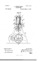
- Figure 1 represents in front elevation one form of pump selected by me to illustrate this invention.
- Fig. 2 is a right-hand end elevation of the pump shown in Fig. 1.
- Figs. 3 and 4 are vertical sections of one of the pump-cylinders, together with its valve, the figures showing the piston in difierent positions.
- Figs. 5 and 6 are modifications to be referred to, and Fig. 7 a detail showing two cylinders connected.
- the frame A is of suitable shape and construction to sustain the working parts, it having suitable bear-in gs for the main driving-shaft a, upon which are mounted the usual fast and loose pulleys a a
- the shaft a outside the frame A has keyed or otherwise rigidly secured to its opposite ends the pinions a in mesh with and driving the larger gear-wheels 1), fast on and rotating the shaft b, journaled in suitable bearings in the frame.
- B B represent the pump-cylin ders sustained upon the frame, and which in the particular pump shown are two in number, and as each of these pump-cylinders with its valve-operating mechanism, piston, and means to operate the same are similar in construction I shall herein proceed to describe in detail only one of the said cylinders with its valve and piston, it being understood that the other is substantially of the same construction, like letters representing like parts.
- Each cylinder B is preferably open at its under side or bottom, as at b Figs. 3 and 4, and the said cylinder contains a suitable piston b fitted to move tightly within the cylinder and provided with suitable packingrings, whereby the said piston, particularly at its upper side, moves in close contact with the annular wall of the cylinder without clearance between the same and the said cylinder, so that when the said piston has been moved into its uppermost position in contact with the top cylinder-head B there is substantially no clearance whatsoever between the piston and the cylinder-head in the cylinder proper.
- the piston b in the particularconstruction shown is provided at its under side with a depending exteriorly-threaded boss I), in which is formed a hemispherical recess formin g part of a socket N, to be referred to.
- I1n' mediat-ely below this boss 1) and drawn upwardly and held thereto by means of a nut 6 threaded upon the'said boss, is a collar b also provided at its upper side with a hemispherical recessor socket, which cooperates with the socketin boss 12 to form the elongated chamber or recess 19 to receive the ball 0 on the end of the piston-rod c, which latter extends downwardly through the collar 19 to the cross-head 0 to which it is rigidly connected, said cross-head moving between suitable guides c formed in the frame of the pump.
- the cross-head has a wrist-pin 0 to which is jointed one end of the pitman or connecting-rod c jointed at its opposite end to a crank-pin c on the gear-wheel b, so that as the wheel b is rotated the piston will be reciprocated within the cylinder.
- the preferred construction I provide a lost motion between the piston and its actuating means for a purpose to be hereinafter described, and in the present construction such lost motion is provided between the balllike end cof the piston c and the ends of the elongated socket or recess 19 on the piston.
- F represents the positively-actuated valve, shown as a slide-valve seated upon the upper face of the top cylinder-head, said valve being acted upon at its upper side by the springactuated plate f, which presses the valve always upon its seat, as in mypatent referred to.
- the plate f is provided with two ports or passages f f one of which, as f, constitutes theinlet-passage, which is connected with the vessel or bulbs to be exhausted, while the other passage f isconnectedwith or constitutes the exhaust-passage through which the air is exhausted from the cylinder, the port f being in the present instance shown as and preferably axially in line with the port 6, while the port or passage f is offset at one side.
- the valve F as herein shown, is provided with two ports f f, the former of which is straight and the lattercurved, the former port connecting the inlet-passage f with the port 6 when the valve is in one of its positions, Fig. 4, while the port f connects the said port 6 with the exhaust-passage f when the valve is in its opposite position, Fig. 3.
- the latter is connected at its opposite sides by links f f with the upper ends of the valve-operating levers f f (see Fig. 2,) pivoted at f f to the frame and provided with depending arms f f, extended into suitable positions to be acted upon and moved by the operation of the pump to effect movement of the valve.
- the arm f is extended down to the gear-wheel b and stands in a po-" sition to be acted upon by a pin f 13 on said wheel, and shown by dotted lines, Fig. 2,while the arm f terminates adjacent the cross-head when the latter is in its lowermost position, and is provided with a roller or other suitable stud f which is acted upon by the camplate 1" on the cross-head c Having now described in detail the several parts in the pump, the operation of the same is as follows: Referring to Figs.
- the piston is shown in its lowermost position, having drawn the cylinder full of air by its previous downstroke, after which the valve F was moved into its extreme right-hand position shown, placing the cylinder and its port 6 in direct communication with the outlet-passage f Assuming the gear-wheel b to be rotating in the direction of the arrow Fig.
- valve F While the parts are in this position, and before the piston begins its downward movement, which would permit air to again enter the port 6, the valve F is shifted into such position, Fig. 4, as will prevent the return of any of the air previously excluded, the parts moving frictionally in contact one with the other, and being actuated mechanically, thereby obviating any leaky joints or contacts and dispensing with the use of oil.
- the lost motion between the crank c and the piston b permits the valve to be thus shifted before the piston changes its direction of movement, so that none of the air expelled from the cylinder can be return ed thereinto before the valve moves, nor can any of the air drawn into the cylinder from the lampbulbs be forced back again thereinto, for the valve in each case moves in one instance to cut olf the exhaust and in the other to out off the inlet before the change in direction of movement of the piston.
- the plug employed to fill the port e or to fill the exhaustport, to thereby exclude all air therefrom and take up the clearance may be moved or actuated from a moving part of the pump in any manner found most convenient; but I prefer to mount the plug directly upon the piston, as herein shown, the piston thus constituting a moving part of the pump which actuates the valve, the only requisite in any construction being that the plug shall enter the port between the piston when the latter is at the end of its stroke and the valve to displace and thereby expel all air which would otherwise remain in the port between the piston and valve.
- Fig. 5 represents one construction, different from that shown in the principal figures, wherein the plug 0 is mounted to slide in suitable guideways in the cylinder-head, said plug as it slides to the left between the side walls of the port acting to. fill and close the said port and thereby expel all fluid there from.
- the plug 0, as shown, is moved by a link 0, actuated in a manner similar to the links f f, said plug being at the proper times moved between the piston and valve to close or fill the port for the purpose specified.
- Fig. 6 shows another slightly-modified form or construction in which the plug includes practically the entire upper part of the piston, the operation, however, being the same as in Figs. 1 to 4, inclusive.
- ⁇ Vhile I have herein shown two independent cylinders, yet it is obvious that any number maybe employedin the same pump, and while Iprefer to operate each cylinder independently of the other, as shown, yet they maybe operated otherwise if desired-as, for i11- stance, draw from one to the other, as represented by Fig. 7.
- I claim- 1 In a vacuum-pump, a cylinder having an outlet-port, a piston in said cylinder, a plug adapted to enter and fill said port to exclude the fluid therefrom, connections between said plug and a moving part of the pump, whereby the plug is moved to enter and completely fill said port at the end of a piston stroke, a valve for opening and closing said port, and valve-actuating mechanism positively to move said valve across and in contact with the top of said plug when the latter is in position filling said port, substantially as described.
- a cylinder having an outlet-port, a piston in said cylinder, a plug on said piston adapted when the piston is at the end of its stroke to enter and fill said port and thereby exclude all fluid therefrom, a valve for opening and closing said port, and valve actuating mechanism positively to move said valve across and in contact with the top of said plug when the latter is in position filling said port, substantially as described.
- a vacuum-pump a cylinder, and exhaust-port therefor, combined with a piston in said cylinder, means to move the same and to cause a dwell thereof at one end of each stroke, a plug actuated by a moving part of the pump to enter said exhaust-port, and completely fill the same during the period of dwell of the piston, and a valve mechanism also actuated during said period of dwell to cut off said exhaust-port, substantially as described.
Landscapes
- Engineering & Computer Science (AREA)
- Mechanical Engineering (AREA)
- General Engineering & Computer Science (AREA)
- Compressors, Vaccum Pumps And Other Relevant Systems (AREA)
Description
(No Model.) 3 Sheets-Sheet 1.
A. BERRENBERG.
VACUUM PUMP.
No. 582,256. Patented May 11, 1 897.
3% 3 370 6071 aZb8r rre7%e y (No Model.) 3 Sheets-Sheet 2.
AlBERRENBERG. VACUUM PUMP.
N0. 582,256. Patented May 11, 1897.
.f J J w-b-bes-ses. lfizlewvov fad azeril errevtbetgt PateqtedMay 11, 1897.
w/v 0A 4 a m I a li'l wr/ wsses.
AL BERT BERRENBERG, OF BOSTON, MASSACHUSET"$.
VACUUM-PUMP.
SPECIFICATION forming part of Letters Patent No. 582,256, dated May 11, 1897.
Application filed June 29, 1893. Serial No: 479,176. (No model.)
To (tZZ whom, it may concern.-
Be it known that I, ALBERT BERRENBERG, of Boston, county of S-ufiollg-State of Massachusetts, have invented an Improvement in Vacuum-Pumps, of which the following description, in connection with the accompanying drawings, is a specification, like letters on the drawings representing like parts.
This invention relates to vacuum-pumps of 1c the class illustrated in United States Patent No. 449,066, dated March 24, 1891.
Pumps of this class are used principally for exhausting the air from incandescent-lamp bulbs, in which the very highest possible de- I 5 gree of vacuum is necessary.
In my patent above referred to I have shown a pump-cylinder provided with a common inlet and outlet port controlled by a suitablyactuated slide-valve to place said port and cylinder alternately in communication with the inlet and exhaust pipes or passages of the pump. 111 my said patent, however, when the pump-piston is at the end of its upstroke in contact with the top cylinder-head the port 2 5 extending through the cylinder-head from the cylinder to the valve-seat would ordinarily contain a certain amount of air, which could not be expelled because the piston could not enter this port to displace or exclude the air.
This air, if permitted to remain in the port at the end of each stroke, would immediately rexpand back into the pump-cylinder at the beginning of the next succeeding downstroke and would expand from this back into the 3 5 lamp-bulbs and would be sufficient to prevent the desired vacuum being obtained. In my patent above referred to, however, to obviate this difficulty as far as possible I have provided an oil-reservoir, the oil from which at each downstroke of the piston flows into and fills the cylinder and the port referred to and absorbs like a sponge a certain quantity of air. This oil, charged with air, is then expelled from the cylinder, thereby taking with 5 it a certain quantity of air'which it has ab sorbed. When the piston in the patent referred to reaches the end of its upstroke and contacts with the cylinder-head, the port instead of being filled with air is filled with oil,
which is supposed to displace a greater part of the air, the only air remaining in the port being such quantity as has been absorbed and is held in suspension by the quantity of oil contained in the port. WVhile this quantity of air thus carried in suspension, and which can never be expelled by the piston, is Very slight, yet it has been found sufficient to reduce the vacuum in the lamp-bulbs below the desired point, for this oil, immediately flowing back into the cylinder at the next suc- 6o ceedin g downstroke, takes with it the air which it has absorbed, this airbeing returned again to the cylinder practically as fast as it is expelled therefrom and is sufficient to materially lower the vacuum obtainable.
Vacuumpumps have also been made in which lift-valves are employed, but in the use of valves of this class no springs can be employed to keep the valves to their seats, for the reason that the rarefied air in the pump would not be sufficient to lift the valves from their seats against the action of the springs, and such air would simply be compressed between the piston and its cylinder-head. On the other hand, if the springs are omitted in 7 5- order that the valves may lift easily, there is not sufficient pressure in the rarefied air to seat the valves firmly upon their seats. The springs must therefore be omitted in order that the valves may lift easily, and to obviate the latter difficulty-viz. that the rarefied air will not seat the valves properlyit is now customary to flood the valve-seats and valves with oil, which when the valves are seated, forms an air-sealing orair-tight film between the valves and their seat. In all these constructions, however, in which oil is employed the oil absorbs more or less air, which, with the oil, is simply expelled from the cylinder and returns again immediately thereto, the oil and air thus returned being sufficient to materially reduce the desired vacuum.
The object of this present invention is to provide a pump substantially entirely mechanical in its operation and which, Without the use of any oil whatsoever, is capable of producing a higher degree of vacuum than any pump heretofore known to me.
To this end I employ a slide-valve, as in my Patent No. 449,066, before referred to, which, no
being positively moved by the pump mechanism at the proper times, obviates any difficulty which is present when the lift-valves are e1nployed, so that it is not necessary to flood the valve and valve-seat with oil in order to obtain a tight seating of the valve upon its seat. There is left then only the portleading from the cylinder to the valve-seat from which the air must be expelled at the end of each stroke, and instead of filling this port with oil to displace the air, as heretofore, which is open to the objections above mentioned, I provide a mechanically-actuated plug, which at the end of each upstroke of the piston is caused to enter and completely fill the port between the piston and the valve-seat, and thereby displace all air from the said port. In a pump embodying my invention, therefore, the piston contacts with the cylinder-head at the end of its stroke and thereby expels all air from the cylinder proper, the plug enters the port between the piston and the valve and thereby displaces and expels all airfrom the said port, which is the only clearance between the piston and the valve, and, lastly, the slidevalve, by being moved mechanically upon its seat and also open and in contact with the plug which fills the port, cuts off all air which is above the valve-seat and is itself firmly held upon its seat by means which render the use of oil unnecessary. I am thus enabled by mechanical means to expel the air from the cylinder more completely a t each stroke than is possible in pumps now known to me and in which oil is used.
In the drawings, Figure 1 represents in front elevation one form of pump selected by me to illustrate this invention. Fig. 2 is a right-hand end elevation of the pump shown in Fig. 1. Figs. 3 and 4 are vertical sections of one of the pump-cylinders, together with its valve, the figures showing the piston in difierent positions. Figs. 5 and 6 are modifications to be referred to, and Fig. 7 a detail showing two cylinders connected.
Referring to the drawings, in the particular pump which I have selected to illustrate this invention, the frame A is of suitable shape and construction to sustain the working parts, it having suitable bear-in gs for the main driving-shaft a, upon which are mounted the usual fast and loose pulleys a a The shaft a outside the frame A has keyed or otherwise rigidly secured to its opposite ends the pinions a in mesh with and driving the larger gear-wheels 1), fast on and rotating the shaft b, journaled in suitable bearings in the frame.
B B represent the pump-cylin ders sustained upon the frame, and which in the particular pump shown are two in number, and as each of these pump-cylinders with its valve-operating mechanism, piston, and means to operate the same are similar in construction I shall herein proceed to describe in detail only one of the said cylinders with its valve and piston, it being understood that the other is substantially of the same construction, like letters representing like parts.
Each cylinder B is preferably open at its under side or bottom, as at b Figs. 3 and 4, and the said cylinder contains a suitable piston b fitted to move tightly within the cylinder and provided with suitable packingrings, whereby the said piston, particularly at its upper side, moves in close contact with the annular wall of the cylinder without clearance between the same and the said cylinder, so that when the said piston has been moved into its uppermost position in contact with the top cylinder-head B there is substantially no clearance whatsoever between the piston and the cylinder-head in the cylinder proper.
The piston b in the particularconstruction shown is provided at its under side with a depending exteriorly-threaded boss I), in which is formed a hemispherical recess formin g part of a socket N, to be referred to. I1n' mediat-ely below this boss 1) and drawn upwardly and held thereto by means of a nut 6 threaded upon the'said boss, is a collar b also provided at its upper side with a hemispherical recessor socket, which cooperates with the socketin boss 12 to form the elongated chamber or recess 19 to receive the ball 0 on the end of the piston-rod c, which latter extends downwardly through the collar 19 to the cross-head 0 to which it is rigidly connected, said cross-head moving between suitable guides c formed in the frame of the pump. The cross-head has a wrist-pin 0 to which is jointed one end of the pitman or connecting-rod c jointed at its opposite end to a crank-pin c on the gear-wheel b, so that as the wheel b is rotated the piston will be reciprocated within the cylinder.
I11 the preferred construction I provide a lost motion between the piston and its actuating means for a purpose to be hereinafter described, and in the present construction such lost motion is provided between the balllike end cof the piston c and the ends of the elongated socket or recess 19 on the piston.
In order to maintain the ball-like end 0 of the piston normally in the bot-tom of its elongated socket,I have provided a spring (I, which is interposed between a step or sleeve cl, surrounding the piston-rod and seated against the collar b and an ad j u stin g-nut clithreaded upon the piston-rod adjacent the cross-head, this spring acting to separate the piston and piston-rod, thereby keeping the ball-like end to be filled with a plug actuated by a moving part of the pump, the plug being herein shown at 6 fast on and movable with the piston, so that when the latter reaches the end of its upstroke and contacts with the upper cylinder-head B said plug will enter and completely fill the port e and all clearance between the piston and the valve-seat.
F represents the positively-actuated valve, shown as a slide-valve seated upon the upper face of the top cylinder-head, said valve being acted upon at its upper side by the springactuated plate f, which presses the valve always upon its seat, as in mypatent referred to.
The plate f is provided with two ports or passages f f one of which, as f, constitutes theinlet-passage, which is connected with the vessel or bulbs to be exhausted, while the other passage f isconnectedwith or constitutes the exhaust-passage through which the air is exhausted from the cylinder, the port f being in the present instance shown as and preferably axially in line with the port 6, while the port or passage f is offset at one side.
The valve F, as herein shown, is provided with two ports f f, the former of which is straight and the lattercurved, the former port connecting the inlet-passage f with the port 6 when the valve is in one of its positions, Fig. 4, while the port f connects the said port 6 with the exhaust-passage f when the valve is in its opposite position, Fig. 3.
In the present construction to move the valve the latter is connected at its opposite sides by links f f with the upper ends of the valve-operating levers f f (see Fig. 2,) pivoted at f f to the frame and provided with depending arms f f, extended into suitable positions to be acted upon and moved by the operation of the pump to effect movement of the valve.
As shown in Fig. 2, the arm f is extended down to the gear-wheel b and stands in a po-" sition to be acted upon by a pin f 13 on said wheel, and shown by dotted lines, Fig. 2,while the arm f terminates adjacent the cross-head when the latter is in its lowermost position, and is provided with a roller or other suitable stud f which is acted upon by the camplate 1" on the cross-head c Having now described in detail the several parts in the pump, the operation of the same is as follows: Referring to Figs. 2 and 3, the piston is shown in its lowermost position, having drawn the cylinder full of air by its previous downstroke, after which the valve F was moved into its extreme right-hand position shown, placing the cylinder and its port 6 in direct communication with the outlet-passage f Assuming the gear-wheel b to be rotating in the direction of the arrow Fig. 2, immediately as the crank-pine passes the dead-center point it will commence to raise the cross-head 0 but as the frictional contact of the piston with its packing-rings ton proper, b begins to move, further rotative movement of the said wheel, after taking up the lost motion, causing the said piston to be moved upwardly within the cylinder to and in contact'with the top cylinderhead B, thereby displacing or expelling all air previously contained in the cylinder proper, forcing said air out through the 8- port f and the exhaust-passage f*, the plug 0 entering the port 6, completely filling the same and excluding all air therefrom, thus obviating entirely all clearance between the piston and the valve when the piston is at the end of its stroke, the top of the plug, when the piston is in such position, lying flush with and in effect constituting a part of the valve-seat upon which the valve F moves. Rotation of the shaft 1) having moved the piston to the end of'its upstroke and in contact with the cylinder-head, as described, further rotative movement of the wheel will act to draw the piston down again into its lowermost position, but before the piston begins its return movement the lost motion between the ball-like head 0 of the piston-rod c and socket in the piston must be again taken up so, that the wheel 1) moves to some distance beyond its upper dead-center before the lost motion is taken up and the piston itself moved toward the bottom of the cylinder. During this time in which the lost motion is being taken up the pin f strikes the lower end of the arm f of the lever and moves the latter to the left to shift the valve into its extreme left-hand position, Fig. 4, the valve being thus shifted while the lost motion is being taken up and while the piston is at rest before it begins its return movement, the piston being held in its uppermost position against the cylinderhead while the cross-head is being drawn down to take up this lost motion by the spring d, which tends to expand and place the parts in the position Fig. 3, with the ball-like head 0 seated in the bottom of its socket 5 After the cross-head has been drawn down sufficiently to take up the lost motion referred to the piston itself is drawn down toward the bottom of the cylinder, thereby drawing the cylinder full of air from the bulbs or vessels being exhausted through the inlet-passage f, the valve still remaining in its position Fig. 4. Just before the piston reaches the end of its downward movement the cam-plate f on the cross-head contacts with the roll-stud on the arm f of the valve-operating lever f and moves said lever to shift the valve to the right into its position Fig. 3 with the port 6 in communication with the exhaust-passage f the valve being thus shifted by and dur- IIO ing the last part of the downward movement of the piston in the cylinder, and while the latter is filled with air continued rotation of the wheel I) carries the crank past the lowest dead-center and begins its upward movement, first taking up the lost motion, as described, and thereafter moving the piston upward to expel the air through the ports e, f, and f From the foregoing description it will be seen that the piston itself by moving in close contact with the cylinder at its upper side and by being moved into direct contact with the cylinder-head at the end of each upstroke absolutely expels from the cylinder proper all air previously contained in the cylinder between it and the cylinder-head, and that any air contained in the port leading from the cylinder to the valve-seat is also completely expelled by the plug 6 so that absolutely all air previously contained in the cylinder and its port e is expelled, the top of the plug moving into position flush with the valveseat. While the parts are in this position, and before the piston begins its downward movement, which would permit air to again enter the port 6, the valve F is shifted into such position, Fig. 4, as will prevent the return of any of the air previously excluded, the parts moving frictionally in contact one with the other, and being actuated mechanically, thereby obviating any leaky joints or contacts and dispensing with the use of oil.
The lost motion between the crank c and the piston b permits the valve to be thus shifted before the piston changes its direction of movement, so that none of the air expelled from the cylinder can be return ed thereinto before the valve moves, nor can any of the air drawn into the cylinder from the lampbulbs be forced back again thereinto, for the valve in each case moves in one instance to cut olf the exhaust and in the other to out off the inlet before the change in direction of movement of the piston.
It is obvious, of course, that the plug employed to fill the port e or to fill the exhaustport, to thereby exclude all air therefrom and take up the clearance, may be moved or actuated from a moving part of the pump in any manner found most convenient; but I prefer to mount the plug directly upon the piston, as herein shown, the piston thus constituting a moving part of the pump which actuates the valve, the only requisite in any construction being that the plug shall enter the port between the piston when the latter is at the end of its stroke and the valve to displace and thereby expel all air which would otherwise remain in the port between the piston and valve.
Fig. 5 represents one construction, different from that shown in the principal figures, wherein the plug 0 is mounted to slide in suitable guideways in the cylinder-head, said plug as it slides to the left between the side walls of the port acting to. fill and close the said port and thereby expel all fluid there from. The plug 0, as shown, is moved by a link 0, actuated in a manner similar to the links f f, said plug being at the proper times moved between the piston and valve to close or fill the port for the purpose specified.
Fig. 6 shows another slightly-modified form or construction in which the plug includes practically the entire upper part of the piston, the operation, however, being the same as in Figs. 1 to 4, inclusive.
This invention is not limited to the particular construction of the various parts herein shown, nor to the particular design of pump herein shown, for it is evident that the gist of this invention may be embodied in different constructions without departing from the spirit and scope of the invention.
\Vhile I have herein shown two independent cylinders, yet it is obvious that any number maybe employedin the same pump, and while Iprefer to operate each cylinder independently of the other, as shown, yet they maybe operated otherwise if desired-as, for i11- stance, draw from one to the other, as represented by Fig. 7.
I claim- 1. In a vacuum-pump, a cylinder having an outlet-port, a piston in said cylinder, a plug adapted to enter and fill said port to exclude the fluid therefrom, connections between said plug and a moving part of the pump, whereby the plug is moved to enter and completely fill said port at the end of a piston stroke, a valve for opening and closing said port, and valve-actuating mechanism positively to move said valve across and in contact with the top of said plug when the latter is in position filling said port, substantially as described.
2. In a vacuum-pump, a cylinder having an outlet-port, a piston in said cylinder, a plug on said piston adapted when the piston is at the end of its stroke to enter and fill said port and thereby exclude all fluid therefrom, a valve for opening and closing said port, and valve actuating mechanism positively to move said valve across and in contact with the top of said plug when the latter is in position filling said port, substantially as described.
3. In a vacuum-pump, a cylinder, and exhaust-port therefor, combined with a piston in said cylinder, means to move the same and to cause a dwell thereof at one end of each stroke, a plug actuated by a moving part of the pump to enter said exhaust-port, and completely fill the same during the period of dwell of the piston, and a valve mechanism also actuated during said period of dwell to cut off said exhaust-port, substantially as described.
4:. In a vacuum-pump, a cylinder having a closed head at one end, an outlet-port therethrough, a piston in said cylinder arranged to contact with the said cylinder-head at In testimony whereof I have signed my 10 every point thereof, a port-closing device, name to this specification in the presence of means to automatically move the same to two subscribing witnesses.
completely close said port When the piston is v at the end of its stroke adjacent thereto, a ALBERT BERRENBERG. slide-Valve for opening and closing said port,
and means to maintain said Valve under Vitnesses:
pressure in intimate contact with said cylin- AUGUSTA E. DEAN,
der-head, substantially as described. FREDERICK L. EMERY.
Publications (1)
| Publication Number | Publication Date |
|---|---|
| US582256A true US582256A (en) | 1897-05-11 |
Family
ID=2650932
Family Applications (1)
| Application Number | Title | Priority Date | Filing Date |
|---|---|---|---|
| US582256D Expired - Lifetime US582256A (en) | Vacuum-pump |
Country Status (1)
| Country | Link |
|---|---|
| US (1) | US582256A (en) |
Cited By (1)
| Publication number | Priority date | Publication date | Assignee | Title |
|---|---|---|---|---|
| US20040076534A1 (en) * | 2002-10-01 | 2004-04-22 | Hammonds Carl L. | Metering pump |
-
0
- US US582256D patent/US582256A/en not_active Expired - Lifetime
Cited By (2)
| Publication number | Priority date | Publication date | Assignee | Title |
|---|---|---|---|---|
| US20040076534A1 (en) * | 2002-10-01 | 2004-04-22 | Hammonds Carl L. | Metering pump |
| US7278836B2 (en) * | 2002-10-01 | 2007-10-09 | Hammonds Technical Services, Inc. | Metering pump |
Similar Documents
| Publication | Publication Date | Title |
|---|---|---|
| US582256A (en) | Vacuum-pump | |
| US1046167A (en) | Pump. | |
| US730495A (en) | Compressing system. | |
| US467578A (en) | And john j | |
| US421346A (en) | Vacuum-pump | |
| US547012A (en) | Edward j | |
| US483268A (en) | Alfred siebert | |
| US2026479A (en) | Compressor | |
| US695133A (en) | Pump. | |
| US990231A (en) | Air-compressor. | |
| US380375A (en) | willans | |
| US434089A (en) | massey | |
| US252110A (en) | Pumping-engine | |
| US523064A (en) | E norris peters co | |
| US746019A (en) | Air-pump. | |
| US607845A (en) | Valve-movement for pumps | |
| US313793A (en) | Compound steam pum ping-engine | |
| US385853A (en) | Ernest c | |
| US539602A (en) | Air-pump | |
| US212039A (en) | Improvement in fluid-motors or motor-engines | |
| US183770A (en) | Improvement in compound engines | |
| US337209A (en) | Hydraulic air-compressor | |
| US578950A (en) | stumpf | |
| US482944A (en) | Force pump | |
| US764629A (en) | Hydraulic motor. |