US5826469A - Threading machine coolant system and method of cooling - Google Patents
Threading machine coolant system and method of cooling Download PDFInfo
- Publication number
- US5826469A US5826469A US08/944,775 US94477597A US5826469A US 5826469 A US5826469 A US 5826469A US 94477597 A US94477597 A US 94477597A US 5826469 A US5826469 A US 5826469A
- Authority
- US
- United States
- Prior art keywords
- die head
- coolant
- workpiece
- valve
- flow
- Prior art date
- Legal status (The legal status is an assumption and is not a legal conclusion. Google has not performed a legal analysis and makes no representation as to the accuracy of the status listed.)
- Expired - Fee Related
Links
- 239000002826 coolant Substances 0.000 title claims abstract description 126
- 238000000034 method Methods 0.000 title claims description 18
- 238000001816 cooling Methods 0.000 title claims description 10
- 238000005520 cutting process Methods 0.000 claims abstract description 96
- 230000004044 response Effects 0.000 claims abstract description 10
- 238000006073 displacement reaction Methods 0.000 claims description 4
- 230000000977 initiatory effect Effects 0.000 claims description 4
- 238000005086 pumping Methods 0.000 claims description 3
- 239000007788 liquid Substances 0.000 claims description 2
- 230000003134 recirculating effect Effects 0.000 claims 3
- LYCAIKOWRPUZTN-UHFFFAOYSA-N Ethylene glycol Chemical compound OCCO LYCAIKOWRPUZTN-UHFFFAOYSA-N 0.000 abstract description 4
- WGCNASOHLSPBMP-UHFFFAOYSA-N hydroxyacetaldehyde Natural products OCC=O WGCNASOHLSPBMP-UHFFFAOYSA-N 0.000 abstract description 3
- 239000003921 oil Substances 0.000 description 14
- 230000005540 biological transmission Effects 0.000 description 8
- 239000002184 metal Substances 0.000 description 8
- 229910052751 metal Inorganic materials 0.000 description 8
- 239000010730 cutting oil Substances 0.000 description 7
- XEEYBQQBJWHFJM-UHFFFAOYSA-N Iron Chemical compound [Fe] XEEYBQQBJWHFJM-UHFFFAOYSA-N 0.000 description 6
- 239000000314 lubricant Substances 0.000 description 6
- 230000006835 compression Effects 0.000 description 5
- 238000007906 compression Methods 0.000 description 5
- 238000004140 cleaning Methods 0.000 description 4
- 238000002845 discoloration Methods 0.000 description 3
- 229910052742 iron Inorganic materials 0.000 description 3
- 239000003208 petroleum Substances 0.000 description 3
- 239000002904 solvent Substances 0.000 description 3
- 238000003860 storage Methods 0.000 description 3
- 230000008016 vaporization Effects 0.000 description 3
- 125000003827 glycol group Chemical group 0.000 description 2
- 230000007246 mechanism Effects 0.000 description 2
- 238000009834 vaporization Methods 0.000 description 2
- XLYOFNOQVPJJNP-UHFFFAOYSA-N water Substances O XLYOFNOQVPJJNP-UHFFFAOYSA-N 0.000 description 2
- 229910000831 Steel Inorganic materials 0.000 description 1
- 241000282485 Vulpes vulpes Species 0.000 description 1
- 230000008901 benefit Effects 0.000 description 1
- 238000009835 boiling Methods 0.000 description 1
- 230000001680 brushing effect Effects 0.000 description 1
- 238000004891 communication Methods 0.000 description 1
- 230000008878 coupling Effects 0.000 description 1
- 238000010168 coupling process Methods 0.000 description 1
- 238000005859 coupling reaction Methods 0.000 description 1
- 238000000203 droplet dispensing Methods 0.000 description 1
- 238000001704 evaporation Methods 0.000 description 1
- 230000008020 evaporation Effects 0.000 description 1
- 230000005484 gravity Effects 0.000 description 1
- 238000010348 incorporation Methods 0.000 description 1
- 238000012423 maintenance Methods 0.000 description 1
- 238000004519 manufacturing process Methods 0.000 description 1
- 239000002923 metal particle Substances 0.000 description 1
- 239000000203 mixture Substances 0.000 description 1
- 230000002093 peripheral effect Effects 0.000 description 1
- 238000007789 sealing Methods 0.000 description 1
- 238000000926 separation method Methods 0.000 description 1
- 239000010959 steel Substances 0.000 description 1
- 238000007514 turning Methods 0.000 description 1
- 238000011144 upstream manufacturing Methods 0.000 description 1
- 239000002699 waste material Substances 0.000 description 1
Images



Classifications
-
- B—PERFORMING OPERATIONS; TRANSPORTING
- B23—MACHINE TOOLS; METAL-WORKING NOT OTHERWISE PROVIDED FOR
- B23Q—DETAILS, COMPONENTS, OR ACCESSORIES FOR MACHINE TOOLS, e.g. ARRANGEMENTS FOR COPYING OR CONTROLLING; MACHINE TOOLS IN GENERAL CHARACTERISED BY THE CONSTRUCTION OF PARTICULAR DETAILS OR COMPONENTS; COMBINATIONS OR ASSOCIATIONS OF METAL-WORKING MACHINES, NOT DIRECTED TO A PARTICULAR RESULT
- B23Q11/00—Accessories fitted to machine tools for keeping tools or parts of the machine in good working condition or for cooling work; Safety devices specially combined with or arranged in, or specially adapted for use in connection with, machine tools
- B23Q11/10—Arrangements for cooling or lubricating tools or work
- B23Q11/1038—Arrangements for cooling or lubricating tools or work using cutting liquids with special characteristics, e.g. flow rate, quality
-
- B—PERFORMING OPERATIONS; TRANSPORTING
- B23—MACHINE TOOLS; METAL-WORKING NOT OTHERWISE PROVIDED FOR
- B23B—TURNING; BORING
- B23B5/00—Turning-machines or devices specially adapted for particular work; Accessories specially adapted therefor
- B23B5/16—Turning-machines or devices specially adapted for particular work; Accessories specially adapted therefor for bevelling, chamfering, or deburring the ends of bars or tubes
- B23B5/165—Workpieces clamped on a bench, e.g. a vice
-
- B—PERFORMING OPERATIONS; TRANSPORTING
- B23—MACHINE TOOLS; METAL-WORKING NOT OTHERWISE PROVIDED FOR
- B23G—THREAD CUTTING; WORKING OF SCREWS, BOLT HEADS, OR NUTS, IN CONJUNCTION THEREWITH
- B23G1/00—Thread cutting; Automatic machines specially designed therefor
- B23G1/22—Machines specially designed for operating on pipes or tubes
-
- Y—GENERAL TAGGING OF NEW TECHNOLOGICAL DEVELOPMENTS; GENERAL TAGGING OF CROSS-SECTIONAL TECHNOLOGIES SPANNING OVER SEVERAL SECTIONS OF THE IPC; TECHNICAL SUBJECTS COVERED BY FORMER USPC CROSS-REFERENCE ART COLLECTIONS [XRACs] AND DIGESTS
- Y10—TECHNICAL SUBJECTS COVERED BY FORMER USPC
- Y10T—TECHNICAL SUBJECTS COVERED BY FORMER US CLASSIFICATION
- Y10T408/00—Cutting by use of rotating axially moving tool
- Y10T408/44—Cutting by use of rotating axially moving tool with means to apply transient, fluent medium to work or product
-
- Y—GENERAL TAGGING OF NEW TECHNOLOGICAL DEVELOPMENTS; GENERAL TAGGING OF CROSS-SECTIONAL TECHNOLOGIES SPANNING OVER SEVERAL SECTIONS OF THE IPC; TECHNICAL SUBJECTS COVERED BY FORMER USPC CROSS-REFERENCE ART COLLECTIONS [XRACs] AND DIGESTS
- Y10—TECHNICAL SUBJECTS COVERED BY FORMER USPC
- Y10T—TECHNICAL SUBJECTS COVERED BY FORMER US CLASSIFICATION
- Y10T82/00—Turning
- Y10T82/10—Process of turning
-
- Y—GENERAL TAGGING OF NEW TECHNOLOGICAL DEVELOPMENTS; GENERAL TAGGING OF CROSS-SECTIONAL TECHNOLOGIES SPANNING OVER SEVERAL SECTIONS OF THE IPC; TECHNICAL SUBJECTS COVERED BY FORMER USPC CROSS-REFERENCE ART COLLECTIONS [XRACs] AND DIGESTS
- Y10—TECHNICAL SUBJECTS COVERED BY FORMER USPC
- Y10T—TECHNICAL SUBJECTS COVERED BY FORMER US CLASSIFICATION
- Y10T82/00—Turning
- Y10T82/20—Lathe for screw cutting
Definitions
- This invention relates to the art of power driven threading machines and, more particularly, to an improved arrangement and method for cooling a workpiece and thread cutting tools during a threading operation.
- a power driven threading machine includes a workpiece chuck mechanism for holding a workpiece to be threaded and which is rotated at a threading speed through a motor driven transmission.
- thread cutting dies are supported on a die head which in turn is supported on a tool carriage which is advanced axially inwardly of the outer end of the rotating workpiece to achieve the cutting of threads thereon.
- the dies are either automatically or manually released from engagement with the workpiece and the carriage and die head are axially withdrawn therefrom.
- the thread cutting oil is contained in a reservoir in the machine, usually located beneath the chuck and tool carriage area, and the oil is pumped to a nozzle or the like supported adjacent the workpiece and dies for directing cutting oil thereonto.
- the cutting oil discharged onto the workpiece and threading dies drops through a chip screen and is returned to the reservoir therebeneath, and the cutting oil is continuously circulated from the reservoir to the nozzle during operation of the machine by a pump driven thereby.
- the oil flows through a filter in the reservoir for removal of chips, dirt and the like.
- an oil free, substantially lubricant free, vaporizable coolant is dispensed onto the workpiece in an area thereof adjacent the point of contact between the workpiece and a cutting die at a rate which provides for the coolant to completely vaporize during threading engagement between the workpiece and dies.
- the coolant cools the workpiece and dies, and the rate of dispensing is controlled to maintain the cutting temperature within a selected temperature range which provides good thread quality.
- the latter is determined at least in part by a thread surface which is free of scaling and discoloration and wherein the thread form is round and there is no tearing on the thread crests and flanks which would affect sealing.
- the coolant is glycol based and vaporization of the coolant provides for the thread cutting operation to be dry. Moreover, there is little or no residue left on the workpiece and no film of oil to which metal chips can cling and which must be removed by a solvent to obtain the same dry condition as is achieved with use of an oil free, volatile coolant in accordance with the present invention.
- Such evaporation also eliminates the return of coolant to the reservoir from which it is pumped to the thread cutting work area, whereby the reservoir can be isolated relative to the work area and defined, for example, by a refillable bottle located within the motor and spindle housing of the machine.
- the reservoir area heretofore required beneath the thread cutting work area can be replaced by a removable container into which the dry metal chips fall.
- Further advantage resides in the fact that the dispensing arrangement for pumping the coolant from the reservoir to the work area does not have to include a filter in that there is no recirculation of the coolant. Thus, the cost of the dispensing arrangement is reduced and maintenance time heretofore required for cleaning and/or replacement of the filter is eliminated.
- the coolant is water soluble which simplifies clean-up following a thread cutting operation. Further in connection with such clean-up, since the accumulated metal chips are dry and there is no oily film on the workpiece or machine parts to be dealt with, clean-up is achieved faster than heretofore possible, whereby the productive time of a machine operator is advantageously increased.
- the coolant is pumped from the reservoir through a flow line having an outlet and a flow control valve arrangement including a pre-adjusted or an adjustable metering valve for adjusting the flow rate of coolant onto the workpiece in the area adjacent the point of engagement of a cutting die therewith.
- the coolant is pumped through the flow line by a pump driven through the threading machine transmission, whereby the pump is operable to pump the coolant from the reservoir in response to operation of the transmission to rotate a workpiece to be threaded.
- the flow control valve arrangement includes a shut-off valve between the reservoir and the metering valve for controlling the flow of coolant from the reservoir to the point of discharge onto the workpiece.
- the shut-off valve advantageously provides selectivity with respect to controlling the flow of coolant from the reservoir to the point of discharge so as to avoid the dispensing of coolant onto the workpiece until the threading dies have engaged therewith to generate heat for vaporizing the coolant.
- the shut-off valve could be manually operated for the latter purpose, it is preferred to incorporate such control with the manipulation of the thread cutting die head into its thread cutting disposition relative to a workpiece and in particular, into thread cutting interengagement of the dies with the rotating workpiece, whereby the torque imposed on the die head is operable to open the shut-off valve.
- Such control of the flow of coolant by the shut-off valve and such control of the operation of the shut-off valve advantageously avoids waste of the coolant.
- the flow of coolant across the metering valve for dispensing onto the workpiece is initiated in response to threading interengagement between the workpiece and thread cutting dies and is interrupted at the end of the thread cutting operation in response to release of the dies from engagement with the workpiece and, thus, removal of the torque from the die head.
- the rate at which the coolant is dispensed onto the workpiece is dependant on a number of factors including the diameter of the workpiece being threaded, the threading or cutting speed, the desired cutting temperature resulting from use of the coolant, and the particular coolant being used.
- a larger diameter workpiece will require the dispensing of more coolant than a smaller diameter workpiece in order to obtain the same end temperature.
- the increased dispensing rate in the latter example can be reduced by reducing the cutting speed of the machine and, therefore, the torque and dry cutting or uncooled temperature of the workpiece.
- a coolant in accordance with the present invention is a liquid having a boiling point below the maximum temperature generated between a workpiece and thread cutting dies during thread cutting without coolant application, and that the amount of coolant to be dispensed onto the workpiece in the area thereof adjacent the point of contact between the workpiece and a thread cutting die is that required to lower the workpiece to a desired end temperature while providing for complete vaporization of the coolant and the cutting of good quality threads.
- the temperature generated during thread cutting interengagement between a workpiece and cutting dies, without coolant application, for workpieces varying in diameter from 1/2" to 3", and driven at standard cutting speeds for the various workpiece diameters varies from about 300° F. to 600° F. for a 1/2" to 3" black or galvanized iron pipe. It is preferred that the end temperature resulting from the dispensing of coolant onto the workpiece in accordance with the present invention be no more than 230° F. and, preferably, be between about 190° F. to 220° F. which provides good quality threads as described above in addition to a workpiece temperature at which the workpiece can be comfortably handled after minimal cooling.
- Another object is the provision of an improved method and system of the foregoing character wherein an oil free, vaporizable coolant is dispensed onto a workpiece being threaded in an area adjacent the point of contact between the workpiece and a thread cutting die at a rate at which the coolant completely vaporizes and evaporates to cool the workpiece and cutting dies while producing good thread quality.
- a further object is the provision of an improved method and system of the foregoing character wherein the coolant is consumed and the metal chips resulting from the threading operation are dry and thus more easily collectible and disposed of than heretofore possible.
- the coolant supply system includes a coolant reservoir which is remotely located relative to the work area and in the form of a refillable receptacle which is closable to enable transportation and/or storage of the threading machine in a non-horizontal disposition without spillage of the coolant.
- Yet a further object is the provision of an improved method and system of the foregoing character wherein delivery of the coolant from the reservoir to the point of dispensing onto the workpiece is controllable to enable precluding flow of the coolant onto the workpiece absent threading interengagement between the workpiece and thread cutting dies.
- Still another object is the provision of an improved method and system of the foregoing character wherein the flow of coolant from the reservoir to the point of dispensing onto the workpiece is controlled by the position of the thread cutting die head relative to the workpiece and thread cutting interengagement between the workpiece and thread cutting dies.
- a further object is the provision of an improved method and system of the foregoing character which optimizes the productive time of a machine operator in connection with use of the machine.
- Another object is the provision of an improved method and system of the foregoing character which minimizes the time and effort required to clean threaded workpieces and the component parts of the threading machine following the performance of threading operations therewith.
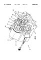
- FIG. 1 is a perspective view of a thread cutting machine having a coolant system in accordance with the present invention and showing the die head of the machine in a non-use position;
- FIG. 2 is a perspective view similar to FIG. 1 and showing the die head in the use position thereof;
- FIG. 3 is a schematic illustration of the coolant supply and dispensing system
- FIG. 4 is a sectional elevation view taken along line 4--4 in FIG. 2 and showing the shut-off valve closed and the position of the die head positioning lug relative to the shut-off valve just prior to initiating the thread cutting operation;
- FIG. 5 is a sectional elevation view taken along line 5--5 in FIG. 2 and showing the shut-off valve closed as in FIG. 4;
- FIG. 6 is a sectional elevation view similar to FIG. 5 and showing the shut-off valve in the open position thereof during a thread cutting operation;
- FIG. 7 is a front elevation view of the die head showing the coolant passageway therethrough.
- FIGS. 1 and 2 illustrate a threading machine which, basically, comprises a base or support 10 which includes a spindle, motor and transmission housing portion 12 at one end and a tooling carriage support portion 14 at the other end.
- a workpiece chuck assembly 16 is supported on housing portion 12 and is driven through the motor and transmission assembly housed in the latter to rotate a workpiece W about a machine axis A.
- a pair of laterally spaced apart tool carriage support rails 18 and 20 have inner ends received in and supported by housing portion 12 of support 10 and outer ends received in and supported by upwardly extending legs 22 of portion 14 of support 10.
- a tooling carriage 24 has laterally opposite sides 26 and 28 respectively slidably received on support rails 18 and 20, and sides 26 and 28 of the carriage are laterally interconnected by axially spaced apart cross members 30 and 32.
- the underside of support rail 20 is provided with teeth, not shown, which engage a pinion supported in side 28 of the carriage and which is rotatable by means of an operating handle 34 to displace the tooling carriage in opposite directions along the support rails.
- Side 26 of carriage 24 supports a thread cutting die head 36 for pivotal displacement relative thereto between a non-use or storage position shown in FIG. 1 and a use position shown in FIG. 2.
- thread cutting dies 38 on the die head are preliminarily positioned relative to workpiece W as described in greater detail hereinafter for cutting threads on the end of workpiece W when carriage 24 is displaced through operating handle 34 to move cutting dies 38 into engagement with the workpiece.
- carriage 24 can pivotally support other tools such as workpiece cutting and reaming tools which, like die head 36, are pivotal relative to the carriage between use and non-use positions.
- Die head 36 has an axis B and, as is well known in connection with die heads, includes a rotatable cam plate assembly, not shown, by which the positions of cutting dies 38 are radially adjustable relative to axis B to facilitate positioning the cutting dies in thread cutting positions which are determined by the diameter of a workpiece to be threaded.
- the cam plate is rotatable between first and second positions in which the cutting dies are respectively in their working positions and in released positions in which the cutting dies are radially outwardly retracted into the die head so as to be out of contact with the workpiece.
- the latter two functions are respectively achieved through a cam plate locking lever 40 and a cam plate positioning lever 42.
- die head 36 With further regard to die head 36, the latter is pivotally mounted on side 26 of carriage 24 by means of a pin 44 extending into a bore 45 provided therefor in side 26 of the die head. In the use position of the die head, the latter is vertically supported by pin 44 on side 26 of the carriage and by a positioning lug 46 on the other side of the die head which engages in a positioning slot 48 provided on side 28 of the carriage by a pair of axially spaced apart upstanding projections 50. As best seen in FIG. 4, positioning slot 48 has a bottom wall 52 which extends laterally inwardly of carriage side 28, and the underside 56 of positioning lug 46 is a planar surface adapted to facially engage surface 52 when positioning lug 46 is fully seated in positioning slot 48 as shown in FIG. 6 set forth more fully hereinafter.
- a temperature of from about 300° F. to 600° F. is generated in the absence of the application of coolant to the workpiece and tooling during the cutting operation. If coolant is not provided, or is inadequate, the heat generated can result in distortion of the cut threads from round, discoloration and/or hardening of the metal from the heat, tearing of the outer ends of the threads and scaling of the thread surface. Additionally, such heat accelerates wearing of the thread cutting dies and thus shortens the life thereof as well as a further reducing the quality of cut threads as the wear progresses.
- a volatile, oil free coolant which is substantially free of lubricant and, preferably, includes a synthetic lubricant amounting to 4% of the coolant composition is dispensed onto a workpiece and tooling during a threading operation at a rate which provides for the coolant to completely vaporize while reducing the temperature of the workpiece to a temperature which provides good thread quality as evidenced by a thread surface which is free of scaling and discoloration, wherein there is no tearing on the thread crests and flanks and the thread form is round.
- the latter temperature is no greater than about 230° F. and is in a temperature range preferably between about 190° F. and 220° F.
- the coolant in reducing the temperature to the latter range, completely vaporizes such that the metal chips resulting from the threading operation are completely dry.
- a suitable coolant providing these results is obtainable from Fuchs Lubricants Co. of Harvey, Ill. under the latter's product designation SBH8 105A.
- the latter is a glycol based coolant which is oil free and contains 4% or less of a lubricant which is synthetic.
- a workpiece temperature of between 190° F. and 220° F. is maintained during a thread cutting operation with the dispensing of the coolant onto the workpiece adjacent the point of contact of one of the cutting dies therewith at a rate of from one to two drops per second.
- the dispensing of the coolant onto the workpiece and tooling can be achieved in any one of a number of different ways including, for example, the manual dispensing from a container having a squeezable or other drop dispensing capability, or by gravity flow from a container across a flow control valve which is opened and closed by the machine operator to control the dispensing rate.
- the dispensing is coordinated with operation of the threading machine and controlled in a manner which optimizes the economic use and consumption of the volatile coolant.
- FIG. 3 A preferred arrangement for the coolant system and the control of the dispensing of coolant onto a workpiece during a threading operation is schematically illustrated in FIG. 3 and is shown in detail in FIGS.
- the coolant system includes a coolant reservoir 58, a coolant pump 60, a normally closed shut-off valve 62, and a flow restricting needle valve 64 and a coolant outlet 66.
- Pump 60 has an inlet connected to reservoir 58 by a line 68 and an outlet connected to valve 62 by a line 70.
- Line 70 is connected back to reservoir 58 by a bypass line 72 whereby, when pump 60 is operating and valve 62 is closed the pumped coolant is returned to the reservoir.
- valve 62 The outlet side of valve 62 is connected to coolant outlet 66 by a passageway 74 in side 28, a passageway 76 in cross member 32 and side 26 of carriage 24, the inner end of pin bore 45, a passageway 78 in pin 44 and a passageway 80 in die head 36.
- Needle valve 64 is in the portion of passageway 74 in cross member 32 and includes a manually displaceable operating member 82 by which the restriction through passageway 74 and thus the drip rate of coolant through coolant outlet 66 can be controlled.
- shutoff valve 62 includes a spindle 84 which is biased to close the valve by a compression spring 86 and, preferably, is displaced by positioning lug 46 on the die head to open the valve.
- Pump 60 is driven in a well known manner by the threading machine motor 88 through a transmission arrangement, not shown. Assuming motor 88 to be turned on so as to drive chuck assembly 16 as described hereinabove, coolant is initially pumped through lines 68 and 70 and back to reservoir 58 through line 72 until such time as shut-off valve 62 opens. When valve 62 opens the coolant is pumped through the shut-off valve and across needle valve 64 to outlet 66 and thence onto the workpiece being threaded. Preferably, as shown in FIG.
- reservoir 58 is preferably in the form of a receptacle such as a plastic bottle having a removable vented cap 90 at the upper end thereof for replenishing the coolant supply in the reservoir.
- Reservoir 58 is conveniently located in spindle, motor and transmission housing portion 12 of the machine base with cap 90 accessible at the top of the housing as shown in FIGS. 1 and 2. It will be appreciated that motor 88 and the pump transmission are located within housing 12 and that pump 60 is suitably supported therein so as to be driven thereby.
- Line 68 to the inlet side of pump 60, the portion of line 70 connected to return line 72 and the latter return line are also located within housing 12.
- shut-off valve 62 is mounted on side 28 of carriage 24 in a position to be operated by positioning lug 46 on die head 36 as described hereinafter. More particularly in this respect, as best seen in FIGS. 4-6, side 28 of the carriage includes a portion 92 extending laterally inwardly of projections 50 and provided with a vertical bore having an upper portion 94 and a lower portion 96, a coolant inlet passage 93 opening laterally into lower portion 96 and a coolant outlet passage 100 opening laterally into upper portion 94 of the bore. Lower portion 96 of the bore is of a larger diameter than upper portion 94, whereby a valve seat 102 is provided in the bore axially between inlet and outlet passages 98 and 100.
- Valve spindle 84 is axially slidably received in the bore and has an inner end provided with a valve element in the form of an O-ring seal 104 for engaging seat 102 to shut off communication between the inlet and outlet passages.
- the lower end of the vertical bore is closed by a plug member 106, and compression spring 86 is located in lower bore portion 96 between plug member 106 and the inner end of spindle 84 to bias valve element 104 against seat 102 to close the valve.
- Spindle 84 is provided with a radially inwardly and axially extending peripheral recess 108 on the downstream side of valve element 104 for communicating inlet and outlet passages 98 and 100 when the valve is open.
- Coolant flow line 70 from pump 60 is connected to inlet passage 98 by a suitable coupling 110, and outlet passage 100 provides the inlet end of passageway 74 described hereinabove.
- positioning lug 46 is located in positioning lug slot 48, underside 56 of the positioning lug engages against outer end 112 of spindle 84 as shown in FIGS. 4 and 5 of the drawing, and the force of compression spring 86 alone is sufficient to bias spindle 84 to its closed position against the weight of the die head imposed thereon through positioning lug 46.
- FIGS. 1 and 2 when a workpiece W is to be threaded the machine operator inserts the workpiece in chuck assembly 16 and pivots die head 36 from its non-use or storage position shown in FIG. 1 to the use position shown in FIG. 2 which is a preliminary working position in which positioning lug 46 is received in positioning slot 48 and rests on end 112 of valve spindle 84 as shown in FIGS. 4 and 5.
- axis B of die head 36 basically coincides with machine axis A.
- carriage 24 is positioned for thread cutting dies 38 to be axially outwardly spaced from the end of workpiece W to be threaded, and compression spring 86 maintains spindle 84 in its upper position whereby shut-off valve 62 is closed.
- the operator turns carriage operating handle 34 to move carriage 24 and thus die head 36 toward workpiece W to initiate the threading operation.
- the workpiece is rotated counterclockwise in FIG. 2 and, immediately upon engagement of cutting dies 38 with the workpiece, torque is imposed on the cutting dies and die head 36 whereby the die head is pivoted counterclockwise in FIG. 2.
- an open top container or tray 114 is removably supported on the bottom of tooling carriage support portion 14 of base 10 in underlying relationship with respect to the work area, whereby metal chips removed from the workpiece during a threading operation fall into the container.
- the coolant evaporates completely upon contacting the hot workpiece, whereby the metal chips that fall into the container are dry. Therefore, when it desired or becomes necessary to clean the machine it is only necessary to remove container 114 and dump the dry chips therefrom. There is no oil or other residue in the container or on the machine, whereby any chips which cling to the receptacle or machine are easily removed such as by brushing or the like. Further, the coolant is preferably water soluble, whereby any residue therefrom is easily washed away and the parts wiped dry. In any event, there is no oily residue or film to which chips, dirt and the like can cling and which would require the use of a solvent in connection with the removal thereof.
- shut-off valve, needle valve and coolant outlet can be associated with a flexible flow line extending from the pump and manually displaceable by the machine operator who would manually open and close the shut-off valve respectively at the beginning and end of a thread cutting operation.
- shut-off and/or needle valve could be separate from and mounted on the carriage instead of being built thereinto, and the valve or valves connected to the reservoir and dispensing outlet through the use of tubing rather than passages in the machine carriage and die head.
- the biasing spring for holding the die head in the preliminary working position could be separate from the valve and directly in engagement with the die head positioning lug.
Landscapes
- Engineering & Computer Science (AREA)
- Mechanical Engineering (AREA)
- Physics & Mathematics (AREA)
- Fluid Mechanics (AREA)
- Auxiliary Devices For Machine Tools (AREA)
Priority Applications (10)
| Application Number | Priority Date | Filing Date | Title |
|---|---|---|---|
| US08/944,775 US5826469A (en) | 1997-10-06 | 1997-10-06 | Threading machine coolant system and method of cooling |
| CA002235055A CA2235055C (fr) | 1997-10-06 | 1998-05-13 | Liquide de refroidissement de machine a fileter et methode de refroidissement |
| CN98118548A CN1109595C (zh) | 1997-10-06 | 1998-09-01 | 车螺纹时冷却工件的方法 |
| JP10246925A JPH11165215A (ja) | 1997-10-06 | 1998-09-01 | ねじ切り装置の冷却装置及び冷却方法 |
| ES98630049T ES2209093T3 (es) | 1997-10-06 | 1998-09-04 | Sistema refrigerante para maquinas rocadoras y metodo de refrigeracion. |
| EP98630049A EP0908268B1 (fr) | 1997-10-06 | 1998-09-04 | Système réfrigérant pour machine à fileter et procédé de refroidissement |
| DE69819102T DE69819102T2 (de) | 1997-10-06 | 1998-09-04 | Kühlsystem für Gewindeschneidmaschine und Verfahren zum Kühlen |
| TW087114976A TW408055B (en) | 1997-10-06 | 1998-09-09 | Method of cooling a workpiece during a thread cutting operation and power driven threading machine |
| CN03107687.4A CN1445055A (zh) | 1997-10-06 | 2003-03-26 | 螺纹机冷却剂系统和冷却方法 |
| CN03107686.6A CN1445054A (zh) | 1997-10-06 | 2003-03-26 | 螺纹机冷却剂系统和冷却方法 |
Applications Claiming Priority (1)
| Application Number | Priority Date | Filing Date | Title |
|---|---|---|---|
| US08/944,775 US5826469A (en) | 1997-10-06 | 1997-10-06 | Threading machine coolant system and method of cooling |
Publications (1)
| Publication Number | Publication Date |
|---|---|
| US5826469A true US5826469A (en) | 1998-10-27 |
Family
ID=25482058
Family Applications (1)
| Application Number | Title | Priority Date | Filing Date |
|---|---|---|---|
| US08/944,775 Expired - Fee Related US5826469A (en) | 1997-10-06 | 1997-10-06 | Threading machine coolant system and method of cooling |
Country Status (8)
| Country | Link |
|---|---|
| US (1) | US5826469A (fr) |
| EP (1) | EP0908268B1 (fr) |
| JP (1) | JPH11165215A (fr) |
| CN (3) | CN1109595C (fr) |
| CA (1) | CA2235055C (fr) |
| DE (1) | DE69819102T2 (fr) |
| ES (1) | ES2209093T3 (fr) |
| TW (1) | TW408055B (fr) |
Cited By (33)
| Publication number | Priority date | Publication date | Assignee | Title |
|---|---|---|---|---|
| WO2006065974A1 (fr) * | 2004-12-14 | 2006-06-22 | Northrop Grumman Ship Systems, Inc. | Procede et appareil de refroidissement de phase |
| US20060133578A1 (en) * | 2004-12-21 | 2006-06-22 | Thomas Saint-Martin | Radiation emission device having a bearing and method of manufacture |
| US20080007849A1 (en) * | 2005-01-27 | 2008-01-10 | Ralf Meschenmoser | Holding assembly and transport arrangement for handling lenses and method for finishing lenses |
| US20080175676A1 (en) * | 2007-01-18 | 2008-07-24 | Prichard Paul D | Milling cutter and milling insert with coolant delivery |
| US20080175677A1 (en) * | 2007-01-18 | 2008-07-24 | Prichard Paul D | Milling cutter and milling insert with coolant delivery |
| US20080175679A1 (en) * | 2007-01-18 | 2008-07-24 | Paul Dehnhardt Prichard | Milling cutter and milling insert with core and coolant delivery |
| US20080175678A1 (en) * | 2007-01-18 | 2008-07-24 | Prichard Paul D | Metal cutting system for effective coolant delivery |
| US20100264091A1 (en) * | 2004-04-21 | 2010-10-21 | Cameron International Corporation | Process for Separating One or More Solids From Water Miscible Fluids and an Apparatus Therefor |
| US7955032B2 (en) | 2009-01-06 | 2011-06-07 | Kennametal Inc. | Cutting insert with coolant delivery and method of making the cutting insert |
| US8328471B2 (en) | 2007-01-18 | 2012-12-11 | Kennametal Inc. | Cutting insert with internal coolant delivery and cutting assembly using the same |
| US20130055862A1 (en) * | 2011-09-06 | 2013-03-07 | Emerson Electric Co. | Portable compact threading machine |
| US8439608B2 (en) | 2007-01-18 | 2013-05-14 | Kennametal Inc. | Shim for a cutting insert and cutting insert-shim assembly with internal coolant delivery |
| US8454274B2 (en) | 2007-01-18 | 2013-06-04 | Kennametal Inc. | Cutting inserts |
| KR101296505B1 (ko) * | 2010-07-30 | 2013-08-13 | 한국산업기술대학교산학협력단 | 파이프 가공장치 및 가공방법 |
| WO2013173945A1 (fr) * | 2012-05-23 | 2013-11-28 | 浙江摩多巴克斯汽配有限公司 | Équipement d'usinage d'extrémité de conduites à stations de travail multiples |
| US20140123820A1 (en) * | 2012-11-05 | 2014-05-08 | Ningbo Zhenming Shaft Co., Ltd. | Process of manufacturing a feed screw |
| US8727673B2 (en) | 2007-01-18 | 2014-05-20 | Kennametal Inc. | Cutting insert with internal coolant delivery and surface feature for enhanced coolant flow |
| US8734062B2 (en) | 2010-09-02 | 2014-05-27 | Kennametal Inc. | Cutting insert assembly and components thereof |
| US8827599B2 (en) | 2010-09-02 | 2014-09-09 | Kennametal Inc. | Cutting insert assembly and components thereof |
| US9101985B2 (en) | 2007-01-18 | 2015-08-11 | Kennametal Inc. | Cutting insert assembly and components thereof |
| CN107252936A (zh) * | 2017-06-30 | 2017-10-17 | 益福光(天津)电子科技有限公司 | 一种电力管装置 |
| US9796033B2 (en) | 2011-09-06 | 2017-10-24 | Ridge Tool Company | Portable compact threading machine |
| CN108406014A (zh) * | 2018-02-05 | 2018-08-17 | 余姚市恒星管业有限公司 | 一种攻丝清洗机以及一种管件接头的生产工艺 |
| CN109202463A (zh) * | 2018-10-26 | 2019-01-15 | 中国水利水电第八工程局有限公司 | 一种钢筋车丝机 |
| US11077509B2 (en) | 2018-03-16 | 2021-08-03 | Milwaukee Electric Tool Corporation | Pipe threader |
| CN113953576A (zh) * | 2021-10-15 | 2022-01-21 | 江阴协宏金属制品有限公司 | 一种铝型材切割装置 |
| CN115121882A (zh) * | 2022-08-10 | 2022-09-30 | 江苏中成紧固技术发展股份有限公司 | 一种用于生产风电螺栓的攻丝装置 |
| US11517967B2 (en) | 2017-11-20 | 2022-12-06 | Hartmetall-Werkzeugfabrik Paul Horn Gmbh | Whirling tool |
| TWI807287B (zh) * | 2021-03-30 | 2023-07-01 | 示昌智造有限公司 | 主軸用出水冷卻結構 |
| US12109623B2 (en) | 2019-11-01 | 2024-10-08 | Milwaukee Electric Tool Corporation | Portable pipe threader |
| US12138702B2 (en) | 2019-11-01 | 2024-11-12 | Milwaukee Electric Tool Corporation | Portable pipe threader |
| CN120326068A (zh) * | 2025-06-18 | 2025-07-18 | 江苏凤灵乐器有限公司 | 一种小提琴调音钮的螺纹切削设备 |
| US12390870B2 (en) | 2021-03-31 | 2025-08-19 | Milwaukee Electric Tool Corporation | Lubrication system for portable pipe threader |
Families Citing this family (9)
| Publication number | Priority date | Publication date | Assignee | Title |
|---|---|---|---|---|
| US6596272B2 (en) | 2001-03-01 | 2003-07-22 | Ultra Biotech Limited | Biological fertilizer compositions comprising poultry manure |
| US8162573B2 (en) | 2004-09-07 | 2012-04-24 | The Tapmatic Corporation | Self-reversing tapping system |
| CN102284709B (zh) * | 2011-08-22 | 2013-01-23 | 昆明水泵厂 | 一种加工s型泵双吸口环的方法 |
| US20150165534A1 (en) * | 2013-12-13 | 2015-06-18 | Ridge Tool Company | Thread forming using an impact driver |
| WO2019223335A1 (fr) * | 2018-05-23 | 2019-11-28 | 盐城哈力动力传动及智能装备产业研究院有限公司 | Équipement d'usinage d'engrenage |
| CN108581074B (zh) * | 2018-05-23 | 2020-04-21 | 盐城哈力动力传动及智能装备产业研究院有限公司 | 一种齿轮加工设备 |
| KR102198863B1 (ko) * | 2020-08-19 | 2021-01-05 | 안진환 | 파이프가공장치 |
| KR102454853B1 (ko) * | 2022-02-03 | 2022-10-13 | 이동수 | 파이프가공장치 |
| CN117086417B (zh) * | 2023-10-11 | 2024-05-21 | 江苏华杰不锈钢制品有限公司 | 一种螺杆螺纹加工设备 |
Citations (20)
| Publication number | Priority date | Publication date | Assignee | Title |
|---|---|---|---|---|
| US384762A (en) * | 1888-06-19 | Petee d | ||
| US710184A (en) * | 1901-03-11 | 1902-09-30 | Charles F Clements | Lubricator and liquid-dispenser. |
| US1196572A (en) * | 1914-04-03 | 1916-08-29 | American Optical Corp | Lens-drill. |
| US1635447A (en) * | 1925-10-29 | 1927-07-12 | Toledo Pipe Threading & Machin | Cutting-tool mounting and controller |
| US1701154A (en) * | 1924-12-29 | 1929-02-05 | Gorham Crosby | Lubricating device |
| US1943642A (en) * | 1928-12-07 | 1934-01-16 | Us Slicing Machine Co | Sharpener for slicing machines |
| US1947874A (en) * | 1931-09-14 | 1934-02-20 | Borden Co | Pipe threading machine |
| US2429741A (en) * | 1945-08-23 | 1947-10-28 | Lester G Barfels | Drill press |
| US2929566A (en) * | 1955-03-03 | 1960-03-22 | Paasche Company | Cooling method and apparatus for metal working |
| US3176330A (en) * | 1962-12-06 | 1965-04-06 | Pipe Machinery Company | Coolant discharge device for cutting tool |
| US3232629A (en) * | 1960-07-01 | 1966-02-01 | Edward F Obear | Automatic gripping chuck |
| US3413667A (en) * | 1966-08-01 | 1968-12-03 | Collins Machinery Corp | Universal supporting and driving apparatus for pipe subjected to threading |
| US3570332A (en) * | 1967-12-18 | 1971-03-16 | Sanders Nuclear Corp | Method of machining super-tough metals |
| US4025219A (en) * | 1974-07-22 | 1977-05-24 | George Fisher Aktiengesellschaft | Pipe machining apparatus, particularly combination pipe threading and cutting machine |
| US4613260A (en) * | 1985-05-10 | 1986-09-23 | Emerson Electric Co. | Thread cutting die head for power driven threading machines |
| US4657068A (en) * | 1985-06-14 | 1987-04-14 | Bruce Zimring | Device for facilitating the circulation of fluid coolant |
| US4787531A (en) * | 1988-02-22 | 1988-11-29 | Emerson Electric Co. | Cover and seal for power driven threading machine oil reservoir |
| US4811639A (en) * | 1988-02-22 | 1989-03-14 | Emerson Electric Co. | Drive bar attachment for threading machines |
| US4949813A (en) * | 1989-02-15 | 1990-08-21 | Kidder Paul R | Lubrication/coolant delivery system |
| US5190421A (en) * | 1991-11-20 | 1993-03-02 | Hardinge Brothers, Inc. | Coolant supply system for a machine tool |
Family Cites Families (7)
| Publication number | Priority date | Publication date | Assignee | Title |
|---|---|---|---|---|
| US2692996A (en) * | 1950-02-24 | 1954-11-02 | Richard A Wallace | Lubrication means for pipe-cutting and threading machines |
| US2916749A (en) * | 1956-10-22 | 1959-12-15 | Ridge Tool Co | Power threading tool having lubrication means for the tool carriage and the die head cutters |
| US3631552A (en) * | 1969-10-17 | 1972-01-04 | Joe A Ivester | Pipe working tool assembly |
| DE2538786A1 (de) * | 1975-09-01 | 1977-03-10 | Albert Fecht | Selbsttaetiger spender von gleit- schmier- und kuehlmittel, insbesondere fuer die spanabhebende metallbearbeitung |
| DE3215407A1 (de) * | 1982-04-24 | 1983-10-27 | Dotzauer, Gernot, 8800 Ansbach | Vorrichtung zur dosierten zufuehrung von oel beim fraesen von werkstuecken |
| JPS60186317A (ja) * | 1984-03-05 | 1985-09-21 | Matsushita Graphic Commun Syst Inc | 自動タツプ立装置 |
| JPS6114815A (ja) * | 1984-06-30 | 1986-01-23 | Koji Kimura | パイプマシンの自動停止装置 |
-
1997
- 1997-10-06 US US08/944,775 patent/US5826469A/en not_active Expired - Fee Related
-
1998
- 1998-05-13 CA CA002235055A patent/CA2235055C/fr not_active Expired - Fee Related
- 1998-09-01 JP JP10246925A patent/JPH11165215A/ja active Pending
- 1998-09-01 CN CN98118548A patent/CN1109595C/zh not_active Expired - Fee Related
- 1998-09-04 ES ES98630049T patent/ES2209093T3/es not_active Expired - Lifetime
- 1998-09-04 DE DE69819102T patent/DE69819102T2/de not_active Expired - Fee Related
- 1998-09-04 EP EP98630049A patent/EP0908268B1/fr not_active Expired - Lifetime
- 1998-09-09 TW TW087114976A patent/TW408055B/zh not_active IP Right Cessation
-
2003
- 2003-03-26 CN CN03107687.4A patent/CN1445055A/zh active Pending
- 2003-03-26 CN CN03107686.6A patent/CN1445054A/zh active Pending
Patent Citations (20)
| Publication number | Priority date | Publication date | Assignee | Title |
|---|---|---|---|---|
| US384762A (en) * | 1888-06-19 | Petee d | ||
| US710184A (en) * | 1901-03-11 | 1902-09-30 | Charles F Clements | Lubricator and liquid-dispenser. |
| US1196572A (en) * | 1914-04-03 | 1916-08-29 | American Optical Corp | Lens-drill. |
| US1701154A (en) * | 1924-12-29 | 1929-02-05 | Gorham Crosby | Lubricating device |
| US1635447A (en) * | 1925-10-29 | 1927-07-12 | Toledo Pipe Threading & Machin | Cutting-tool mounting and controller |
| US1943642A (en) * | 1928-12-07 | 1934-01-16 | Us Slicing Machine Co | Sharpener for slicing machines |
| US1947874A (en) * | 1931-09-14 | 1934-02-20 | Borden Co | Pipe threading machine |
| US2429741A (en) * | 1945-08-23 | 1947-10-28 | Lester G Barfels | Drill press |
| US2929566A (en) * | 1955-03-03 | 1960-03-22 | Paasche Company | Cooling method and apparatus for metal working |
| US3232629A (en) * | 1960-07-01 | 1966-02-01 | Edward F Obear | Automatic gripping chuck |
| US3176330A (en) * | 1962-12-06 | 1965-04-06 | Pipe Machinery Company | Coolant discharge device for cutting tool |
| US3413667A (en) * | 1966-08-01 | 1968-12-03 | Collins Machinery Corp | Universal supporting and driving apparatus for pipe subjected to threading |
| US3570332A (en) * | 1967-12-18 | 1971-03-16 | Sanders Nuclear Corp | Method of machining super-tough metals |
| US4025219A (en) * | 1974-07-22 | 1977-05-24 | George Fisher Aktiengesellschaft | Pipe machining apparatus, particularly combination pipe threading and cutting machine |
| US4613260A (en) * | 1985-05-10 | 1986-09-23 | Emerson Electric Co. | Thread cutting die head for power driven threading machines |
| US4657068A (en) * | 1985-06-14 | 1987-04-14 | Bruce Zimring | Device for facilitating the circulation of fluid coolant |
| US4787531A (en) * | 1988-02-22 | 1988-11-29 | Emerson Electric Co. | Cover and seal for power driven threading machine oil reservoir |
| US4811639A (en) * | 1988-02-22 | 1989-03-14 | Emerson Electric Co. | Drive bar attachment for threading machines |
| US4949813A (en) * | 1989-02-15 | 1990-08-21 | Kidder Paul R | Lubrication/coolant delivery system |
| US5190421A (en) * | 1991-11-20 | 1993-03-02 | Hardinge Brothers, Inc. | Coolant supply system for a machine tool |
Cited By (59)
| Publication number | Priority date | Publication date | Assignee | Title |
|---|---|---|---|---|
| US8728321B2 (en) * | 2004-04-21 | 2014-05-20 | Cameron International Corporation | Process for separating one or more solids from water miscible fluids and an apparatus therefor |
| US20100264091A1 (en) * | 2004-04-21 | 2010-10-21 | Cameron International Corporation | Process for Separating One or More Solids From Water Miscible Fluids and an Apparatus Therefor |
| US7707841B2 (en) | 2004-12-14 | 2010-05-04 | Northrop Grumman Ship Systems, Inc. | Phase cooling method and apparatus |
| WO2006065974A1 (fr) * | 2004-12-14 | 2006-06-22 | Northrop Grumman Ship Systems, Inc. | Procede et appareil de refroidissement de phase |
| US20060133578A1 (en) * | 2004-12-21 | 2006-06-22 | Thomas Saint-Martin | Radiation emission device having a bearing and method of manufacture |
| US7386094B2 (en) * | 2004-12-21 | 2008-06-10 | General Electric Company | Radiation emission device having a bearing and method of manufacture |
| US20080007849A1 (en) * | 2005-01-27 | 2008-01-10 | Ralf Meschenmoser | Holding assembly and transport arrangement for handling lenses and method for finishing lenses |
| US8439608B2 (en) | 2007-01-18 | 2013-05-14 | Kennametal Inc. | Shim for a cutting insert and cutting insert-shim assembly with internal coolant delivery |
| US8202025B2 (en) | 2007-01-18 | 2012-06-19 | Kennametal Inc. | Metal cutting system for effective coolant delivery |
| US20080175678A1 (en) * | 2007-01-18 | 2008-07-24 | Prichard Paul D | Metal cutting system for effective coolant delivery |
| US20080175679A1 (en) * | 2007-01-18 | 2008-07-24 | Paul Dehnhardt Prichard | Milling cutter and milling insert with core and coolant delivery |
| US20110020075A1 (en) * | 2007-01-18 | 2011-01-27 | Kennametal Inc. | Metal cutting system for effective coolant delivery |
| US20110027022A1 (en) * | 2007-01-18 | 2011-02-03 | Kennametal Inc. | Metal cutting system for effective coolant delivery |
| US7883299B2 (en) | 2007-01-18 | 2011-02-08 | Kennametal Inc. | Metal cutting system for effective coolant delivery |
| US20110033249A1 (en) * | 2007-01-18 | 2011-02-10 | Kennametal Inc. | Metal cutting system for effective coolant delivery |
| US9108253B2 (en) | 2007-01-18 | 2015-08-18 | Kennametal Inc. | Roughing cutting insert |
| US7963729B2 (en) | 2007-01-18 | 2011-06-21 | Kennametal Inc. | Milling cutter and milling insert with coolant delivery |
| US7997832B2 (en) | 2007-01-18 | 2011-08-16 | Kennametal Inc. | Milling cutter and milling insert with coolant delivery |
| US8033763B2 (en) | 2007-01-18 | 2011-10-11 | Kennametal Inc. | Metal cutting system for effective coolant delivery |
| US8057130B2 (en) | 2007-01-18 | 2011-11-15 | Kennametal Inc. | Metal cutting system for effective coolant delivery |
| US8079784B2 (en) | 2007-01-18 | 2011-12-20 | Kennametal Inc. | Milling cutter and milling insert with coolant delivery |
| US8079783B2 (en) | 2007-01-18 | 2011-12-20 | Kennametal Inc. | Milling cutter and milling insert with coolant delivery |
| US8092123B2 (en) | 2007-01-18 | 2012-01-10 | Kennametal Inc. | Metal cutting system for effective coolant delivery |
| US8142112B2 (en) | 2007-01-18 | 2012-03-27 | Kennametal Inc. | Metal cutting system for effective coolant delivery |
| US9101985B2 (en) | 2007-01-18 | 2015-08-11 | Kennametal Inc. | Cutting insert assembly and components thereof |
| US8256998B2 (en) | 2007-01-18 | 2012-09-04 | Kennametal Inc. | Metal cutting system for effective coolant delivery |
| US8256999B2 (en) | 2007-01-18 | 2012-09-04 | Kennametal Inc. | Metal cutting system for effective coolant delivery |
| US8328471B2 (en) | 2007-01-18 | 2012-12-11 | Kennametal Inc. | Cutting insert with internal coolant delivery and cutting assembly using the same |
| US8727673B2 (en) | 2007-01-18 | 2014-05-20 | Kennametal Inc. | Cutting insert with internal coolant delivery and surface feature for enhanced coolant flow |
| US20080175677A1 (en) * | 2007-01-18 | 2008-07-24 | Prichard Paul D | Milling cutter and milling insert with coolant delivery |
| US8454274B2 (en) | 2007-01-18 | 2013-06-04 | Kennametal Inc. | Cutting inserts |
| US20080175676A1 (en) * | 2007-01-18 | 2008-07-24 | Prichard Paul D | Milling cutter and milling insert with coolant delivery |
| US7625157B2 (en) | 2007-01-18 | 2009-12-01 | Kennametal Inc. | Milling cutter and milling insert with coolant delivery |
| US7955032B2 (en) | 2009-01-06 | 2011-06-07 | Kennametal Inc. | Cutting insert with coolant delivery and method of making the cutting insert |
| KR101296505B1 (ko) * | 2010-07-30 | 2013-08-13 | 한국산업기술대학교산학협력단 | 파이프 가공장치 및 가공방법 |
| US8734062B2 (en) | 2010-09-02 | 2014-05-27 | Kennametal Inc. | Cutting insert assembly and components thereof |
| US8827599B2 (en) | 2010-09-02 | 2014-09-09 | Kennametal Inc. | Cutting insert assembly and components thereof |
| US8840342B2 (en) | 2010-09-02 | 2014-09-23 | Kennametal Inc. | Finishing cutting insert |
| US9095913B2 (en) | 2010-09-02 | 2015-08-04 | Kennametal Inc. | Cutting inserts |
| US9796033B2 (en) | 2011-09-06 | 2017-10-24 | Ridge Tool Company | Portable compact threading machine |
| US20130055862A1 (en) * | 2011-09-06 | 2013-03-07 | Emerson Electric Co. | Portable compact threading machine |
| US9370835B2 (en) * | 2011-09-06 | 2016-06-21 | Emerson Electric Co. | Portable compact threading machine |
| WO2013173945A1 (fr) * | 2012-05-23 | 2013-11-28 | 浙江摩多巴克斯汽配有限公司 | Équipement d'usinage d'extrémité de conduites à stations de travail multiples |
| US20140123820A1 (en) * | 2012-11-05 | 2014-05-08 | Ningbo Zhenming Shaft Co., Ltd. | Process of manufacturing a feed screw |
| CN107252936B (zh) * | 2017-06-30 | 2018-11-20 | 江苏源清环保科技有限公司 | 一种电力管装置 |
| CN107252936A (zh) * | 2017-06-30 | 2017-10-17 | 益福光(天津)电子科技有限公司 | 一种电力管装置 |
| US11517967B2 (en) | 2017-11-20 | 2022-12-06 | Hartmetall-Werkzeugfabrik Paul Horn Gmbh | Whirling tool |
| CN108406014A (zh) * | 2018-02-05 | 2018-08-17 | 余姚市恒星管业有限公司 | 一种攻丝清洗机以及一种管件接头的生产工艺 |
| US11077509B2 (en) | 2018-03-16 | 2021-08-03 | Milwaukee Electric Tool Corporation | Pipe threader |
| US12220756B2 (en) | 2018-03-16 | 2025-02-11 | Milwaukee Electric Tool Corporation | Pipe threader |
| CN109202463A (zh) * | 2018-10-26 | 2019-01-15 | 中国水利水电第八工程局有限公司 | 一种钢筋车丝机 |
| US12109623B2 (en) | 2019-11-01 | 2024-10-08 | Milwaukee Electric Tool Corporation | Portable pipe threader |
| US12138702B2 (en) | 2019-11-01 | 2024-11-12 | Milwaukee Electric Tool Corporation | Portable pipe threader |
| TWI807287B (zh) * | 2021-03-30 | 2023-07-01 | 示昌智造有限公司 | 主軸用出水冷卻結構 |
| US12390870B2 (en) | 2021-03-31 | 2025-08-19 | Milwaukee Electric Tool Corporation | Lubrication system for portable pipe threader |
| CN113953576B (zh) * | 2021-10-15 | 2024-04-19 | 江阴协宏金属制品有限公司 | 一种铝型材切割装置 |
| CN113953576A (zh) * | 2021-10-15 | 2022-01-21 | 江阴协宏金属制品有限公司 | 一种铝型材切割装置 |
| CN115121882A (zh) * | 2022-08-10 | 2022-09-30 | 江苏中成紧固技术发展股份有限公司 | 一种用于生产风电螺栓的攻丝装置 |
| CN120326068A (zh) * | 2025-06-18 | 2025-07-18 | 江苏凤灵乐器有限公司 | 一种小提琴调音钮的螺纹切削设备 |
Also Published As
| Publication number | Publication date |
|---|---|
| CA2235055C (fr) | 2001-12-11 |
| CN1213597A (zh) | 1999-04-14 |
| TW408055B (en) | 2000-10-11 |
| EP0908268A3 (fr) | 2000-09-27 |
| JPH11165215A (ja) | 1999-06-22 |
| DE69819102T2 (de) | 2004-06-24 |
| EP0908268A2 (fr) | 1999-04-14 |
| DE69819102D1 (de) | 2003-11-27 |
| CN1445054A (zh) | 2003-10-01 |
| CA2235055A1 (fr) | 1999-04-06 |
| ES2209093T3 (es) | 2004-06-16 |
| CN1445055A (zh) | 2003-10-01 |
| CN1109595C (zh) | 2003-05-28 |
| EP0908268B1 (fr) | 2003-10-22 |
Similar Documents
| Publication | Publication Date | Title |
|---|---|---|
| US5826469A (en) | Threading machine coolant system and method of cooling | |
| EP0985490B1 (fr) | Procédé et dispositif de refroidissement d'une pièce | |
| US9383147B2 (en) | Coolant supply apparatus | |
| DE69524404T2 (de) | Verfahren und vorrichtung zum polieren einer halbleiterscheibe | |
| CN211867287U (zh) | 一种钻床的冷却液回收装置 | |
| DE1602876A1 (de) | Kuehlmittelabgabevorrichtung fuer Verspannungswerkzeuge,z.B.Bohrwerkzeuge | |
| DE19915265A1 (de) | Verfahren und Vorrichtung zur Minimalmengen-Kühlschmierung bei Zerspannprozessen | |
| US20180272489A1 (en) | Adjustable automatic dispensing apparatus | |
| US6908373B1 (en) | Shear blade sharpener method and apparatus | |
| CN217666936U (zh) | 一种棒料攻丝成型装置 | |
| CN213225517U (zh) | 一种五金配件打磨抛光装置 | |
| KR101610823B1 (ko) | 자동차용 오일 교환장치 | |
| JPH11138387A (ja) | 加工機における工具への給油装置 | |
| US1635447A (en) | Cutting-tool mounting and controller | |
| KR20230053103A (ko) | 공작기계의 쿨런트 공급장치 | |
| CN2143541Y (zh) | 机具用气体与冷却液一体喷注装置 | |
| JP4182410B2 (ja) | 吐出量制御スプレーホルダー | |
| US3559511A (en) | Drill coolant method and apparatus | |
| US1635702A (en) | Cutting compound distribution system | |
| CN221935554U (zh) | 一种用于磨机润滑油路管件的锯切圆锯床 | |
| JPH045230Y2 (fr) | ||
| JP3780511B2 (ja) | 砥石連れ回り空気流利用方法及び装置並びに同装置を用いた研削装置 | |
| CN213670025U (zh) | 一种泵体加工用喷涂装置 | |
| US6119896A (en) | Fluid dispenser device | |
| EP1388392A1 (fr) | Applicateur de lubrifiant |
Legal Events
| Date | Code | Title | Description |
|---|---|---|---|
| AS | Assignment |
Owner name: EMERSON ELECTRIC COMPANY, OHIO Free format text: ASSIGNMENT OF ASSIGNORS INTEREST;ASSIGNOR:HARADEM, DONALD A.;REEL/FRAME:008839/0792 Effective date: 19971001 |
|
| AS | Assignment |
Owner name: EMERSON ELECTRIC COMPANY, MISSOURI Free format text: RE-RECORD TO CORRECT THE ADDRESS OF THE ASSIGNEE PREVIOUSLY RECORDED ON REEL 8839, FRAME 0792;ASSIGNOR:HARADEM, DONALD A.;REEL/FRAME:008973/0722 Effective date: 19971001 |
|
| FPAY | Fee payment |
Year of fee payment: 4 |
|
| FPAY | Fee payment |
Year of fee payment: 8 |
|
| REMI | Maintenance fee reminder mailed | ||
| LAPS | Lapse for failure to pay maintenance fees | ||
| STCH | Information on status: patent discontinuation |
Free format text: PATENT EXPIRED DUE TO NONPAYMENT OF MAINTENANCE FEES UNDER 37 CFR 1.362 |
|
| FP | Lapsed due to failure to pay maintenance fee |
Effective date: 20101027 |