US5845526A - Method for producing pipe having polygon-shaped closed cross-section and device therefor - Google Patents
Method for producing pipe having polygon-shaped closed cross-section and device therefor Download PDFInfo
- Publication number
- US5845526A US5845526A US08/831,477 US83147797A US5845526A US 5845526 A US5845526 A US 5845526A US 83147797 A US83147797 A US 83147797A US 5845526 A US5845526 A US 5845526A
- Authority
- US
- United States
- Prior art keywords
- die
- strip
- rough pipe
- pipe
- vicinity
- Prior art date
- Legal status (The legal status is an assumption and is not a legal conclusion. Google has not performed a legal analysis and makes no representation as to the accuracy of the status listed.)
- Expired - Fee Related
Links
Images




Classifications
-
- B—PERFORMING OPERATIONS; TRANSPORTING
- B21—MECHANICAL METAL-WORKING WITHOUT ESSENTIALLY REMOVING MATERIAL; PUNCHING METAL
- B21C—MANUFACTURE OF METAL SHEETS, WIRE, RODS, TUBES, PROFILES OR LIKE SEMI-MANUFACTURED PRODUCTS OTHERWISE THAN BY ROLLING; AUXILIARY OPERATIONS USED IN CONNECTION WITH METAL-WORKING WITHOUT ESSENTIALLY REMOVING MATERIAL
- B21C37/00—Manufacture of metal sheets, rods, wire, tubes, profiles or like semi-manufactured products, not otherwise provided for; Manufacture of tubes of special shape
-
- B—PERFORMING OPERATIONS; TRANSPORTING
- B21—MECHANICAL METAL-WORKING WITHOUT ESSENTIALLY REMOVING MATERIAL; PUNCHING METAL
- B21C—MANUFACTURE OF METAL SHEETS, WIRE, RODS, TUBES, PROFILES OR LIKE SEMI-MANUFACTURED PRODUCTS OTHERWISE THAN BY ROLLING; AUXILIARY OPERATIONS USED IN CONNECTION WITH METAL-WORKING WITHOUT ESSENTIALLY REMOVING MATERIAL
- B21C37/00—Manufacture of metal sheets, rods, wire, tubes, profiles or like semi-manufactured products, not otherwise provided for; Manufacture of tubes of special shape
- B21C37/06—Manufacture of metal sheets, rods, wire, tubes, profiles or like semi-manufactured products, not otherwise provided for; Manufacture of tubes of special shape of tubes or metal hoses; Combined procedures for making tubes, e.g. for making multi-wall tubes
- B21C37/10—Making tubes with seams being neither welded nor soldered, e.g. riveted seams
- B21C37/104—Making tubes with seams being neither welded nor soldered, e.g. riveted seams the tubes having a special shape, e.g. polygonal tubes
-
- B—PERFORMING OPERATIONS; TRANSPORTING
- B21—MECHANICAL METAL-WORKING WITHOUT ESSENTIALLY REMOVING MATERIAL; PUNCHING METAL
- B21C—MANUFACTURE OF METAL SHEETS, WIRE, RODS, TUBES, PROFILES OR LIKE SEMI-MANUFACTURED PRODUCTS OTHERWISE THAN BY ROLLING; AUXILIARY OPERATIONS USED IN CONNECTION WITH METAL-WORKING WITHOUT ESSENTIALLY REMOVING MATERIAL
- B21C37/00—Manufacture of metal sheets, rods, wire, tubes, profiles or like semi-manufactured products, not otherwise provided for; Manufacture of tubes of special shape
- B21C37/06—Manufacture of metal sheets, rods, wire, tubes, profiles or like semi-manufactured products, not otherwise provided for; Manufacture of tubes of special shape of tubes or metal hoses; Combined procedures for making tubes, e.g. for making multi-wall tubes
- B21C37/15—Making tubes of special shape; Making tube fittings
- B21C37/155—Making tubes with non-circular section
Definitions
- the present invention relates to a method for continuously producing pipes, each having a polygon-shaped closed cross-section taken perpendicularly to the feeding direction of a strip of metal, by using a feed-bending method, and a device therefor.
- the pies obtained by this method and device are applicable to reinforcing members for bumpers or the like.
- Examples of the conventional method or device using the feed-bending method described above include a continuous forming method of long-sized channel materials with a press die (Japanese Patent publication No. sho 57-52128), a feed-bending forming method of circular pipes with an edge bending system (Japanese Patent publication No. Hei 2-61333), a continuous forming device of pipes of various lengths (Japanese Utility Model publication No. Hei 5-27208) and a forming device for plate like long size body (Japanese Patent application laid-open No. Hei 3-221213).
- widthwise edges of strips are bent inwardly in its width direction with a curvature approximately identical to that of desired circular pipes between an inlet defined by a punch and die and an outlet defined thereby (edge bending), which causes resulting pressed products to have closed circular cross-sections taken perpendicularly to the feeding direction.
- edge bending causes resulting pressed products to have closed circular cross-sections taken perpendicularly to the feeding direction.
- pipes, each having a polygon-shaped closed cross-section are intended to produce with the edge bending system described above, designed ridgelines of the strip, which define ridgelines of resulting pipes, would extend in a direction crossing the feeding direction, and shift in parallel therewith every pressing operation. This results in that the strip would be bent and crushed repeatedly along the designed ridgelines, and resulting pipes would become brittle due to metal fatigue.
- a first aspect of the method of producing pipes, each having a polygon-shaped closed cross-section, in accordance with the present invention, is a feed-bending method including the steps of successively feeding a strip of metal between a first die and a second die by predetermined feed lengths, and pressing the strip with the first die and second die synchronously with feeding, thereby continuously forming pipes, each having a polygon-shaped closed cross-section taken perpendicularly to the feeding direction.
- the method includes the steps of gradually bending a strip of metal along designed ridgelines defining ridgelines of pipes, each having a polygon-shaped closed cross-section, which extend in the feeding direction, from those close to widthwise ends of the strip towards those near a widthwise center thereof in the course between the vicinity of an inlet defined by the first and second dies and the vicinity of a middle thereof, thereby forming a rough pipe which is connected to the strip and has interior angles inside the designed ridgelines, each of which is approximately identical to that inside a corresponding desired ridgeline, and of which widthwise ends are substantially flush with each other and abuttable each other, and correcting the rough pipe form both the inside and outside thereof in the vicinity of the outlet defined by the first and second dies, thus obtaining a product pipe connected to the rough pipe.
- the rough pipe connected to the work is initially obtained.
- the work is merely bent gradually along designed ridgelines defining desired ridgelines of a product pipe, because they extend in the feeding direction, which does not cause brittleness due to metal fatigue.
- the work is bent along designed ridgelines which extend in the feeding direction
- the work which has been bent only along the designed ridgelines close to the widthwise ends may deform in a twisting direction in the surfaces corresponding to segments extending in parallel with the pressing direction in the cross-section taken perpendicularly to the feeding direction.
- camber may be generated with a longitudinal central portion as the center of curvature.
- the work is bent gradually along the designed ridgelines from those close to the widthwise ends towards those near the widthwise center. Therefore, the above-described surfaces of the work have a short length in a pressing direction, thus mininizing the above camber therein. With this arrangement, however, camber of the work is still inevitable, and may remain in a resulting pipe as a pressed product. Accordingly, if pipes having no or reduced camber are desired, camber must be restrained. To this end, the step of producing a rough pipe may be performed with an inclination or curvature which causes oppositely curved camber given thereto (first means).
- the rough pipe may be produced while forming bead-like projections on a central surface of the work in a direction perpendicular to the feeding direction thereof, and then crushing the projections formed (second means).
- second means elongation can be given to the central surface of the work to restrain tensile strain near the widthwise ends, thereby restraining or eliminating wrinkles thereabout, and to restrain springback in the work, thereby preventing the work from being caught by the first die and/or second die.
- the vicinity of the widthwise ends may be pressed to crush the wrinkles therein.
- a resulting rough pipe has interior angles inside designed ridgelines, which are generally identical to those inside corresponding ridgelines of a desired pipe. And the widthwise ends thereof extend flush with each other and are abuttable each other. The widthwise ends of the resulting rough pipe, however, may be separated due to a residual stress, because they have been elongated and shrinked by repeatedly bending operations.
- the rough pipe is corrected from the inside and outside thereof in the vicinity of the outlet defined by the first and second dies. It is preferable that the rough pipe is initially bent greatly such that the distance between the widthwise ends is smaller than that of a desired pipe, and then, this bending force is released. This results in the widthwise ends of the rough pipe abutting each other, and the wrinkles therein beind crushed.
- pipes, each having a polygon-shaped closed cross-section taken perpendicular to the feeding direction can be obtained continously.
- FIG. 1 is a schematic longitudinal sectional view of a forming device used in an embodiment of a method in accordance with the present invention
- FIG. 2 is a cross-sectional view of the forming device taken along the line II--II of FIG. 1;
- FIG. 3 is a cross-sectional view of the forming device taken along the line III--III of FIG. 1;
- FIG. 4 is a cross-sectional view of the forming device taken along the line IV--IV of FIG. 1;
- FIG. 5 is a cross-sectional view of the forming device taken along the line V--V of FIG. 1;
- FIG. 6 is a perspective view of a product pipe obtained with the method in accordance with the present invention.
- FIG. 7(A) is a cross-sectional view taken in the direction A of FIG. 6;
- FIG. 7(B) is a cross-sectional view taken in the direction B of FIG. 6;
- FIG. 7(C) is a cross-sectional view taken in the direction C of FIG. 6;
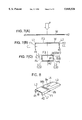
- FIG. 8 is a partially enlarged view of FIG. 6;
- FIG. 9 is a graph showing the relation between the forming force and curvature
- FIG. 10 is a partially enlarged plane view of FIG. 6;
- FIG. 11 is a partially enlarged perspective view of FIG. 6;
- FIG. 12 is a graph showing the relation between the over-bending amount and maximum wrinkle depth
- FIG. 13 is a partially enlarged perspective view of FIG. 6;
- FIG. 14 is a graph showing the relation between the over-bending amount and opening amount of strip ends.
- FIGS. 1 through 5 illustrate a forming device used in the present embodiment.
- a movable table 2 is positioned over a stationary table 1.
- the movable table 2 includes a press ram (not shown) which is movable in the pressing direction P.
- a die 3 as a first die is secured to the stationary table 1 while a punch 4 as one part of a second die is secured to the movable table 2.
- a feeding means (not shown) adapted to feed a strip (work) W in a horizontal feeding direction S is provided on the left side of the forming device.
- An upper part of an outer surface 5a of the main body 5 in the central section defined by the pressing direction P and feeding direction S is formed flat near the inlet of the forming device, and then curves upwardly.
- the upper part of the outer surface 5a of the main body 5 in the section perpendicular to the feeding direction S is also formed flat near the inlet of the forming device.
- the outer surface 5a of the main body 5 is gradually bent through 90 degrees along lines adapted to bend the work W along designed ridgelines L1 and L2.
- the outer surface 5a of the main body 5 is gradually bent along lines adapted to bend the work W along designed ridgelines L3 and L4. As shown in FIGS.
- the designed ridgelines L1 and L2 are located near widthwise ends e1 and e2 of the work W while the designed ridgelines L3 and L4 are located next to the designed ridgelines L1 and L2, namely near a widthwise center of the work W.
- These designed ridgelines L1, L2, L3 and L4 extend in the feeding direction S.
- the width of the lower part of the main body 5 decreases with the distance between ends of the outer surface 5a.
- the mandrel 6 has an outer surface 6a connected to the outer surface 5a of the main body 5, and, as shown in FIG. 5, is gradually bent through 90 degrees along lines adapted to bend the work W along the designed ridgelines L3 and L4.
- the under surface 4a of the punch 4 is gradually bent through 90 degrees along lines adapted to bend the work W along designed ridgelines L3 and L4. As shown in FIG. 5, the width of the punch 4 is reduced to about the sum of the width of the mandrel 6 and double of the thickness of the work W.
- a pair of slide tables 7 and 8 are secured to left and right of the stationary table 1.
- Sliders 11 and 12 are slidably provided on the slide tables 7 and 8.
- the sliders 11 and 12 are biased in directions away from each other with pushing springs 9 and 10.
- Correction punches 13 and 14 adapted to correct a rough pipe WO with the mandrel 6 and the punch 4 are secured to the sliders 11 and 12.
- These correction punches 13 and 14 along with the punch 4 define a second die.
- Slide cams 15 and 16 are secured to the movable table 2.
- the slide cams 15 and 16 have inclination surfaces 15a and 16a, respectively.
- inclination surfaces 15a and 16a face each other and conform to inclination surfaces 11a and 12a of the sliders 11 and 12, respectively.
- the inclination surfaces 15a and 1la are positioned upwardly of the inclination surfaces 16a and 12a, which enables the correction punches 13 and 14 to move at timings with a predetermined time lag.
- the work W of metal is successively fed between the main body 5, mandrel 6, punch 4 and correction punches 13 and 14 of the forming device thus arranged by predetermined feed lengths.
- the work W is pressed with the main body 5, mandrel 6, punch 4 and correction punches 13 and 14, thus subjecting the work W to a feed-bending method.
- a pipe W1 is formed continuously.
- the rough pipe W0 which is connected to the work W is formed with the main body 5 and punch 4. Since the designed ridgelines L1 through L4 extend in the feeding direction S, the work W is merely bent gradually along the designed ridgelines L1 through L4. This does not cause brittleness of the work due to metal fatigue.
- the work W is curved upwardly, which restrains generation of tensile strain in flange surfaces F1, F2 (FIG. 7(B)) of the work W, which correspond to segments parallel to the pressing direction P in the cross-section taken perpendicularly to the feeding direction S, on the side of the ends e1 and e2 in relation to the central line CL extending perpendicularly to the pressing direction P, and also restrains generation of compressive strain in the flange surfaces F1, F2 on the side of the central portion thereof in relation to the central line CL. Furthermore, in the first step, a desired curvature is given to the pipe W1.
- the work W is bent along the designed ridgelines L3 and L4 to obtain the rough pipe W0.
- the interior angles inside the desinged ridgelines L1 through L4 of the rough pipe W0 are 90 degrees, which are approximately identical to those inside the ridgelines L5 through L8 of the product tube W1, and the widthwise ends e1 and e2 are generally flush with each other and abuttable.
- the ends e1 and e2 may separate into an open state due to residual stress, because they have elongated and shrinked by repeatedly bending operations.
- the correcting punches 13 and 14 along with the mandrel 6 and the under surface of the punch 4, which faces the mandrel 6, correct the rough pipe W0 from the inside and outside thereof. More specifically, the correcting punches 13 and 14 initially bend the rough pipe W0 greatly such that, as shown in FIGS. 7(C) and 10, the distance between the surfaces F4 and F5 of the rough pipe W0, which extend in parallel with the pressing direction P, becomes smaller than that of corresponding surfaces of a product pipe W1. After that, this bending force is released. As shown in FIG. 5, the correcting punches 13 and 14 are arranged such that when the slide cams 15 and 16 descend, the correcting punch 13 moves prior to the correcting punch 14.
- the long end e1 initially abuts the mandrel 6, and then the short end e2 abuts the mandrel 6.
- open ends e1 and e2 are superimposed on each other, and wrinkles therein are crushed.
- the pipe W1 having an angular closed cross-section taken perpendicularly to the feeding direction, which is connected to the rough pipe W0, can be obtained continuously. Then, the pipe W1 is cut along the cut line C to obtain a product pipe applicable to a reinforcing member of a bumper, for example.
Landscapes
- Engineering & Computer Science (AREA)
- Mechanical Engineering (AREA)
- Bending Of Plates, Rods, And Pipes (AREA)
Applications Claiming Priority (2)
| Application Number | Priority Date | Filing Date | Title |
|---|---|---|---|
| JP8-083821 | 1996-04-05 | ||
| JP08382196A JP3347573B2 (ja) | 1996-04-05 | 1996-04-05 | 断面多角形閉状態の管の製造方法及びそのための型 |
Publications (1)
| Publication Number | Publication Date |
|---|---|
| US5845526A true US5845526A (en) | 1998-12-08 |
Family
ID=13813365
Family Applications (1)
| Application Number | Title | Priority Date | Filing Date |
|---|---|---|---|
| US08/831,477 Expired - Fee Related US5845526A (en) | 1996-04-05 | 1997-03-31 | Method for producing pipe having polygon-shaped closed cross-section and device therefor |
Country Status (5)
| Country | Link |
|---|---|
| US (1) | US5845526A (fr) |
| EP (1) | EP0799656B1 (fr) |
| JP (1) | JP3347573B2 (fr) |
| KR (1) | KR100224930B1 (fr) |
| DE (1) | DE69703761T2 (fr) |
Cited By (3)
| Publication number | Priority date | Publication date | Assignee | Title |
|---|---|---|---|---|
| US6745448B2 (en) * | 2000-02-04 | 2004-06-08 | Ricoh Company, Ltd. | Pipe body and forming method of the same |
| CN104028596A (zh) * | 2014-05-23 | 2014-09-10 | 宁波赛乐福板材成型技术有限公司 | 板材连续渐近成型装置 |
| US20150375288A1 (en) * | 2008-09-25 | 2015-12-31 | Jfe Steel Corporation | Closed structure parts, method and press forming apparatus for manufacturing the same |
Families Citing this family (9)
| Publication number | Priority date | Publication date | Assignee | Title |
|---|---|---|---|---|
| JP3613702B2 (ja) | 1999-09-21 | 2005-01-26 | トヨタ自動車株式会社 | 閉断面を有する構造部材、その製造装置およびその製造方法 |
| JP3850196B2 (ja) * | 2000-02-04 | 2006-11-29 | 株式会社リコー | パイプ体の製造方法、製造装置、これらにより製造されたパイプ体及びこのパイプ体を用いた画像形成装置 |
| JP4538997B2 (ja) * | 2001-08-09 | 2010-09-08 | トヨタ紡織株式会社 | プレス装置 |
| JP2008080381A (ja) * | 2006-09-28 | 2008-04-10 | Yorozu Corp | 湾曲中空パイプの製造方法 |
| KR100790773B1 (ko) | 2006-11-27 | 2008-01-03 | 주식회사 성우하이텍 | 동시 성형용 롤 포밍 장치 및 그 방법 |
| JP5206805B2 (ja) * | 2011-01-24 | 2013-06-12 | Jfeスチール株式会社 | 閉断面構造部品の製造方法及び装置 |
| WO2013094580A1 (fr) * | 2011-12-21 | 2013-06-27 | 本田技研工業株式会社 | Structure de montage de bras de suspension |
| WO2013153681A1 (fr) * | 2012-04-13 | 2013-10-17 | Jfeスチール株式会社 | Dispositif et procédé de production de composant presentant une structure a section transversale fermee |
| KR102132652B1 (ko) * | 2019-06-18 | 2020-07-10 | 서종태 | 빔류의 성형장치 |
Citations (9)
| Publication number | Priority date | Publication date | Assignee | Title |
|---|---|---|---|---|
| US1708872A (en) * | 1923-11-01 | 1929-04-09 | Richmond Fireproof Door Co | Strip-forming machine |
| GB328890A (en) * | 1928-10-03 | 1930-05-08 | Ig Farbenindustrie Ag | Method of manufacturing shaped sections of uniform thickness from sheet metal strips |
| US1785025A (en) * | 1927-12-02 | 1930-12-16 | Guarsteel Safety Stair Co | Square tubing for newel posts |
| US2942643A (en) * | 1957-10-11 | 1960-06-28 | Pucci Joseph | Method of and apparatus for cutting and shaping strip material |
| US3119432A (en) * | 1961-05-15 | 1964-01-28 | Pullmax Ab | Sheet metal forming tools |
| JPS6254523A (ja) * | 1985-04-04 | 1987-03-10 | Nippon Steel Metal Prod Co Ltd | 角形鋼管素管の成形装置 |
| EP0384287A2 (fr) * | 1989-02-15 | 1990-08-29 | Enami Seiki Mfg. Co., Ltd. | Appareil pour former une pièce longue en tôle |
| JPH02261333A (ja) * | 1989-03-31 | 1990-10-24 | Kanegafuchi Chem Ind Co Ltd | ケーキ用油中水型油脂組成物 |
| US5104026A (en) * | 1990-03-26 | 1992-04-14 | Shape Corporation | Apparatus for roll-forming an automotive bumper |
-
1996
- 1996-04-05 JP JP08382196A patent/JP3347573B2/ja not_active Expired - Fee Related
-
1997
- 1997-03-31 US US08/831,477 patent/US5845526A/en not_active Expired - Fee Related
- 1997-04-04 KR KR1019970012474A patent/KR100224930B1/ko not_active Expired - Fee Related
- 1997-04-04 EP EP97105632A patent/EP0799656B1/fr not_active Expired - Lifetime
- 1997-04-04 DE DE69703761T patent/DE69703761T2/de not_active Expired - Fee Related
Patent Citations (10)
| Publication number | Priority date | Publication date | Assignee | Title |
|---|---|---|---|---|
| US1708872A (en) * | 1923-11-01 | 1929-04-09 | Richmond Fireproof Door Co | Strip-forming machine |
| US1785025A (en) * | 1927-12-02 | 1930-12-16 | Guarsteel Safety Stair Co | Square tubing for newel posts |
| GB328890A (en) * | 1928-10-03 | 1930-05-08 | Ig Farbenindustrie Ag | Method of manufacturing shaped sections of uniform thickness from sheet metal strips |
| US2942643A (en) * | 1957-10-11 | 1960-06-28 | Pucci Joseph | Method of and apparatus for cutting and shaping strip material |
| US3119432A (en) * | 1961-05-15 | 1964-01-28 | Pullmax Ab | Sheet metal forming tools |
| JPS6254523A (ja) * | 1985-04-04 | 1987-03-10 | Nippon Steel Metal Prod Co Ltd | 角形鋼管素管の成形装置 |
| EP0384287A2 (fr) * | 1989-02-15 | 1990-08-29 | Enami Seiki Mfg. Co., Ltd. | Appareil pour former une pièce longue en tôle |
| JPH03221213A (ja) * | 1989-02-15 | 1991-09-30 | Enami Seiki:Kk | 板状長尺体の成形装置 |
| JPH02261333A (ja) * | 1989-03-31 | 1990-10-24 | Kanegafuchi Chem Ind Co Ltd | ケーキ用油中水型油脂組成物 |
| US5104026A (en) * | 1990-03-26 | 1992-04-14 | Shape Corporation | Apparatus for roll-forming an automotive bumper |
Cited By (8)
| Publication number | Priority date | Publication date | Assignee | Title |
|---|---|---|---|---|
| US6745448B2 (en) * | 2000-02-04 | 2004-06-08 | Ricoh Company, Ltd. | Pipe body and forming method of the same |
| US20040140011A1 (en) * | 2000-02-04 | 2004-07-22 | Takafumi Kondou | Pipe body and forming method of the same |
| US7044169B2 (en) | 2000-02-04 | 2006-05-16 | Ricoh Company, Ltd. | Pipe body and forming method of the same |
| US20060185751A1 (en) * | 2000-02-04 | 2006-08-24 | Takafumi Kondou | Pipe body and forming method of the same |
| US7318455B2 (en) | 2000-02-04 | 2008-01-15 | Ricoh Company, Ltd. | Pipe body and forming method of the same |
| US20150375288A1 (en) * | 2008-09-25 | 2015-12-31 | Jfe Steel Corporation | Closed structure parts, method and press forming apparatus for manufacturing the same |
| CN104028596A (zh) * | 2014-05-23 | 2014-09-10 | 宁波赛乐福板材成型技术有限公司 | 板材连续渐近成型装置 |
| CN104028596B (zh) * | 2014-05-23 | 2016-01-06 | 宁波赛乐福板材成型技术有限公司 | 板材连续渐近成型装置 |
Also Published As
| Publication number | Publication date |
|---|---|
| KR970069171A (ko) | 1997-11-07 |
| JPH09271847A (ja) | 1997-10-21 |
| EP0799656A2 (fr) | 1997-10-08 |
| DE69703761T2 (de) | 2001-08-09 |
| DE69703761D1 (de) | 2001-02-01 |
| EP0799656A3 (fr) | 1998-07-15 |
| KR100224930B1 (ko) | 1999-10-15 |
| EP0799656B1 (fr) | 2000-12-27 |
| JP3347573B2 (ja) | 2002-11-20 |
Similar Documents
| Publication | Publication Date | Title |
|---|---|---|
| US4148426A (en) | Method and apparatus for manufacturing metal pipe | |
| US5845526A (en) | Method for producing pipe having polygon-shaped closed cross-section and device therefor | |
| RU2535414C2 (ru) | Способ штамповки компонента, имеющего l-образную форму (варианты) | |
| KR102339921B1 (ko) | 프레스 성형용의 금속판, 프레스 성형 장치 및 프레스 부품의 제조 방법 | |
| KR102361285B1 (ko) | 프레스 부품의 제조 방법, 프레스 성형 장치 및 프레스 성형용의 금속판 | |
| KR20190056438A (ko) | 프레스 성형품의 제조 방법 및 제조 장치 | |
| JP2010023078A (ja) | ワークの曲げ加工方法および装置 | |
| KR102003631B1 (ko) | 프레스 성형 방법 및 프레스 성형 금형 | |
| EP1088606B1 (fr) | Elément porteur de section fermée | |
| TWI590885B (zh) | A method of manufacturing a press-formed product and a press-formed product, and a manufacturing apparatus of the press-formed product | |
| KR101579028B1 (ko) | 폐단면 구조 부품의 제조 방법 및 장치 | |
| KR102579287B1 (ko) | 절곡가공 방법 | |
| WO2016171229A1 (fr) | Procédé permettant de produire un produit moulé à la presse, produit moulé à la presse et dispositif de pressage | |
| CN113226584B (zh) | 冲压成形方法 | |
| WO2016147703A1 (fr) | Procédé de formage à la presse et outil de formage à la presse | |
| JP7302747B2 (ja) | プレス成形品の製造方法及びプレス成形装置 | |
| KR102545155B1 (ko) | 프레스 성형 방법 | |
| JPH0238287B2 (fr) | ||
| KR20140079949A (ko) | 롤 포밍 장치 | |
| US4403495A (en) | Apparatus for bending channel section members | |
| GB2094681A (en) | Bending | |
| KR20200112989A (ko) | 프레스 성형품의 설계 방법, 프레스 성형 금형, 프레스 성형품 및 프레스 성형품의 제조 방법 | |
| WO2022118622A1 (fr) | Procédé de production d'un élément en acier | |
| JP2021176646A (ja) | プレス部品の製造方法、プレス成形用の金属板、及び高張力鋼板 | |
| JP7102976B2 (ja) | プレス成形用素材の創製方法およびその創製装置 |
Legal Events
| Date | Code | Title | Description |
|---|---|---|---|
| AS | Assignment |
Owner name: AMINO CORPORATION, JAPAN Free format text: ASSIGNMENT OF ASSIGNORS INTEREST;ASSIGNORS:KADOMA, YOSHIAKI;NIHASHI, IWAO;OGAWA, HIDEO;AND OTHERS;REEL/FRAME:008739/0569 Effective date: 19970418 Owner name: TOYOTA JIDOSHA KABUSHIKI KAISHA, JAPAN Free format text: ASSIGNMENT OF ASSIGNORS INTEREST;ASSIGNORS:KADOMA, YOSHIAKI;NIHASHI, IWAO;OGAWA, HIDEO;AND OTHERS;REEL/FRAME:008739/0569 Effective date: 19970418 |
|
| FEPP | Fee payment procedure |
Free format text: PAYOR NUMBER ASSIGNED (ORIGINAL EVENT CODE: ASPN); ENTITY STATUS OF PATENT OWNER: LARGE ENTITY |
|
| FPAY | Fee payment |
Year of fee payment: 4 |
|
| FPAY | Fee payment |
Year of fee payment: 8 |
|
| REMI | Maintenance fee reminder mailed | ||
| LAPS | Lapse for failure to pay maintenance fees | ||
| STCH | Information on status: patent discontinuation |
Free format text: PATENT EXPIRED DUE TO NONPAYMENT OF MAINTENANCE FEES UNDER 37 CFR 1.362 |
|
| FP | Lapsed due to failure to pay maintenance fee |
Effective date: 20101208 |