US5857404A - Peeling machine - Google Patents
Peeling machine Download PDFInfo
- Publication number
- US5857404A US5857404A US08/855,231 US85523197A US5857404A US 5857404 A US5857404 A US 5857404A US 85523197 A US85523197 A US 85523197A US 5857404 A US5857404 A US 5857404A
- Authority
- US
- United States
- Prior art keywords
- machine according
- peeling machine
- knife
- drive
- supported
- Prior art date
- Legal status (The legal status is an assumption and is not a legal conclusion. Google has not performed a legal analysis and makes no representation as to the accuracy of the status listed.)
- Expired - Lifetime
Links
- 235000013311 vegetables Nutrition 0.000 claims abstract description 40
- 238000004891 communication Methods 0.000 claims abstract description 5
- 238000005520 cutting process Methods 0.000 claims description 9
- 239000000969 carrier Substances 0.000 claims description 5
- 239000000463 material Substances 0.000 claims description 5
- 241000234427 Asparagus Species 0.000 description 6
- 235000005340 Asparagus officinalis Nutrition 0.000 description 6
- 240000008067 Cucumis sativus Species 0.000 description 4
- 235000009849 Cucumis sativus Nutrition 0.000 description 3
- 238000010276 construction Methods 0.000 description 3
- 244000000626 Daucus carota Species 0.000 description 2
- 235000002767 Daucus carota Nutrition 0.000 description 2
- 238000004140 cleaning Methods 0.000 description 2
- 238000013461 design Methods 0.000 description 2
- 238000012986 modification Methods 0.000 description 2
- 230000004048 modification Effects 0.000 description 2
- 238000009420 retrofitting Methods 0.000 description 2
- 235000010799 Cucumis sativus var sativus Nutrition 0.000 description 1
- 244000088415 Raphanus sativus Species 0.000 description 1
- 235000006140 Raphanus sativus var sativus Nutrition 0.000 description 1
- 244000292071 Scorzonera hispanica Species 0.000 description 1
- 235000018704 Scorzonera hispanica Nutrition 0.000 description 1
- 230000005540 biological transmission Effects 0.000 description 1
- 230000000694 effects Effects 0.000 description 1
- 238000012423 maintenance Methods 0.000 description 1
- 238000000034 method Methods 0.000 description 1
Images




Classifications
-
- A—HUMAN NECESSITIES
- A23—FOODS OR FOODSTUFFS; TREATMENT THEREOF, NOT COVERED BY OTHER CLASSES
- A23N—MACHINES OR APPARATUS FOR TREATING HARVESTED FRUIT, VEGETABLES OR FLOWER BULBS IN BULK, NOT OTHERWISE PROVIDED FOR; PEELING VEGETABLES OR FRUIT IN BULK; APPARATUS FOR PREPARING ANIMAL FEEDING- STUFFS
- A23N7/00—Peeling vegetables or fruit
- A23N7/04—Peeling asparagus
Definitions
- the present invention relates to a peeling machine, and in particular to a peeling machine for stalk-like vegetables.
- Different types of peeling machines for stalk-like vegetables such as asparagus, cucumber, carrots, black salsify, radishes, or the like, are known in the art. They typically comprise a plurality of knife stations successively arranged on a machine frame along a direction of travel of the vegetables. They also typically include a plurality of pairs of feed rollers which are each supported between two neighboring knife stations to transport the stalk-like vegetables and to push them through the knife stations. Circumferential portions of the vegetable stalks are respectively peeled off in the knife stations. The pairs of feed rollers are connected to a drive means for applying the necessary advance movement.
- An apparatus of the above-mentioned type is, for example, described in German patent 44 12 561.
- the prior-art peeling machines are each designed for a specific type of product to be processed, for example, a machine might be designed for asparagus stalks.
- the product has substantially uniform dimensions, so that the type and arrangement of the pairs of feed rollers as well as the knife stations can be adapted thereto. As a result, the products to be processed can no longer be changed at will or can only be changed by taking considerable efforts in altering the configuration of the machine.
- the peeling machine of the present invention includes a plurality of knife stations which are successively arranged in the direction of travel of the vegetable on a machine frame.
- a plurality of pairs of feed rollers are supported between successive knife stations, with each pair of feed rollers being connected to a means for rotationally driving the feed rollers.
- Each knife station is supported on a quick-change carrier that is removably secured to the machine frame.
- each of the feed rollers is supported by means of a drive shaft on a pivot arm the pivot arm being supported on the machine frame to pivot about a stationary shaft.
- the stationary shaft is arranged in a direction perpendicular to the direction of travel of the vegetables.
- the stationary shaft preferably supports a rotatable first drive wheel of the drive means, which is in driving communication with a second drive wheel that is secured to the drive shaft.
- the peeling machine of the invention is characterized by several considerable advantages. Since the feed roller itself is supported on a pivot arm, it is possible to vary the distance between the feed rollers over a wide range without any constructional changes or retrofitting work being required. Hence, the most different vegetables can be processed in any desired order; for instance, cucumbers, carrots, asparagus, etc. Since each feed roller is driven via its respective first and second drive wheels, the drive parameters of the feed roller are not changed by a pivoting of the pivot arm. This means that the adjusted advance speed can be exactly maintained, so that optimum cutting conditions prevail at the knives.
- the drive of the peeling machine can be of a simple construction which is not prone to failure, and thus a high degree of operational reliability is ensured.
- the first drive wheel and the second drive wheel are advantageously designed as gears which are in meshing engagement with each other. A slip-free drive is thereby ensured on the one hand and it is possible on the other hand to provide the two gears with different reference diameters to additionally provide a transmission function.
- the first drive wheel is directly coupled with a motor of the drive means, for instance by connection to a pulley which is driven by a belt drive of the drive means.
- the belt drive may be designed as a double-sided toothed belt which winds around the pulley.
- the feed roller is preferably supported via a freewheel device on the drive shaft in order to take into account slight changes in diameter of the vegetables to be processed, and thus to avoid any damage to the vegetable stalks.
- a pressure exerting means is arranged between the pivot arm and the machine frame, to assure that the feed rollers provide a sufficient contact pressure on the vegetable stalks.
- the pressure exerting means may comprise a piston-cylinder unit or a spring means. Particularly with relatively heavy vegetables, such as cucumbers, a reliable transportation is ensured through sufficient contact pressure by the feed rollers.
- the feed rollers are preferably secured to the drive shaft by a bayonet lock.
- the feed rollers can thus be removed easily, for performing cleaning or maintenance work, and for other tasks.
- the knife stations it may be preferable to operate the knife stations by means of a control device that controls the movement and contact pressure of the knives.
- the knives are preferably closed when a vegetable to be processed is located in the area of the knife station, whereas the knives are opened in the absence of a cutting operation. This serves to apply an optimum cutting force and to remove peeled-off surface portions or chips of the product to be processed.
- the feed roller can be adapted with respect to its material and dimensions.
- the feed roller can be made from a flexible material or a rigid material.
- the shape of the feed roller may have a cylindrical shape, or may be of some other shape, such as having reduced diameter in its center portion.
- each of the knife stations supported on a quick-change carrier that is secured to the machine frame.
- the individual knife stations can be removed more easily. This facilitates both the cleaning of the knife stations and the maintaining of the peeling machine, such as the replacement of the knives.
- the quick-change carriers make the use of different knife stations possible, which allows for knife stations that are exactly adapted to specific products to be processed.
- the quick-change carrier comprises a vertical carrier plate which is provided with a recess for guiding the vegetables therethrough.
- the carrier plate additionally serves as a baffle element to intercept and discharge peeled-off chips or surface portions of the preceding knife station.
- each knife of the knife station is supported on an inlet plate, which is pivotally mounted on the carrier plate.
- inlet plate which is pivotally mounted on the carrier plate.
- the pivot axis of the inlet plate prefferably be substantially located in the plane of the carrier plate.
- An elastic bias serves, among other things, to exert a sufficient contact pressure of the knives during the cutting operation.
- the knives may be preferable for the knives to have either a straight or an arcuate shape.
- the peeling machine of the invention is suited for a horizontal and also a vertical passage of the products.
- a horizontal arrangement is particularly preferable in the case of elongated, lightweight vegetables, such as asparagus, whereas heavy and relatively short products of an increased diameter, such as cucumbers, are preferably processed with the aid of a vertically arranged peeling machine.
- FIG. 1 is a perspective partial view of a machine frame and feed rollers of a peeling machine embodying features of the present invention.
- FIG. 2 is a top plan view of an asparagus traveling through feed rollers and a knife unit of the peeling machine of FIG. 1.
- FIG. 3 is an elevational view of a feed roller supported on a pivot arm, and connected to a drive means, of the peeling machine of FIG. 1.
- FIG. 4 is a top plan view of a pair of feed rollers of the peeling machine of FIG. 1.
- FIG. 5 is a top plan view of a knife station of the peeling machine of FIG. 1.
- FIG. 6 is a bottom plan view of the knife station depicted in FIG. 5, depicting detachable aspects of the invention.
- FIG. 7 is an elevational view depicting support structure for supporting the feed roller of FIG. 3.
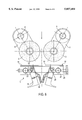
- FIG. 8 is an elevational view of the knife station depicted in FIG. 5.
- FIG. 1 is a diagrammatic view of a machine frame 2 which has supported thereon a plurality of pairs of feed rollers 3. Drive and support of the pairs of feed rollers will be described in detail below.
- FIG. 2 is a very simplified illustration showing the travel of an asparagus stalk through a knife unit 1.
- the figure does not show the peeling off of the surface in detail; rather, the application of the knife unit and the pairs of feed rollers to a vegetable to be processed are illustrated in the figure.
- the individual components of the knife unit will be described in detail hereinafter.
- FIG. 3 is a lateral sectional view of a portion of a machine frame 2 which carries a stationary shaft 6.
- stationary shaft 6 carries an elongated pivot arm 5, the other end of which has rotatably supported thereon a drive shaft 4 by means of bearings 21.
- a feed roller 3 is secured by means of a bayonet lock 12 to the lower end of drive shaft 4 for rotation therewith.
- the feed roller 3 may have a cylindrical shape, but may also have a reduced diameter in its center portion, as shown in the right half of the FIG. 3 roller.
- the upper end portion of drive shaft 4 extends through a recess 22 of the machine frame 2, so that the machine frame does not obstruct any pivotal movement of pivot arm 5 and thus of drive shaft 4.
- drive shaft 4 is connected to a freewheel device 30 comprising a second drive wheel 8 (gear) which meshes with a first drive wheel 7 that is rotatably supported on stationary shaft 6.
- the freewheel device blocks in one direction to ensure transportation of the products, but permits a damage-free advance movement of the products in cases where the traveling speed thereof is greater than the circumferential speed of the feed rollers 3.
- a pulley 9 which is connected to the first drive wheel 7 for rotation therewith is also rotatably supported on stationary shaft 6. Hence, a rotation of pulley 9 will automatically effect a rotation of the first drive wheel 7 and thus a rotation of the second drive wheel 8 which, in turn, will drive the drive shaft 4 and thus feed roller 3.
- This drive connection is independent of the respective pivotal position of pivot arm 5.
- FIG. 3 shows a detector bolt 23 which is secured in the center portion of pivot arm 5.
- Detector bolt 23 cooperates with a sensor 13 which reports the respective position of pivot arm 5 to a control device (not shown).
- FIG. 4 is a top view of the arrangement shown in FIG. 3.
- the illustrated pressure exerting means can only be seen in the right half of the figure; this is also applicable to sensor 13, which may also be present in double form.
- FIG. 4 particularly shows the arrangement of the two pulleys 9 and of the belt drive 10.
- the latter winds in S-shaped configuration around the two pulleys 9.
- the belt drive 10 drives all of the pulleys 9 of the individual pairs of feed rollers and is additionally guided over a drive wheel (not shown) which is assigned to a motor.
- a spring means 11 which is designed as a tension spring for biasing the pivot arms 5 into a closing position.
- the spring means 11 may also be provided a piston-cylinder unit 24 for pivoting the respective pivot arm 5 and for exerting a sufficient contact pressure of the feed rollers 3 on the vegetable to be transported.
- a straight arrow indicates the direction of travel of the vegetable stalk whilst the arcuate double-headed arrows illustrate the pivoting possibility of the pivot arms 5 and of the feed rollers 3 (shown in FIG. 3) which are supported thereon.
- FIG. 4 shows how the sensor 13 is assigned to the detector bolt 23.
- bolt 23 is received in a recess of the machine frame 2 (not shown in more detail), so that the detector bolt 23 does also not obstruct a pivotal movement of the pivot arm 5.
- FIG. 5 is a diagrammatic top view on a pair of feed rollers 3 and shows the direction of travel of the vegetable through the feed rollers (see arrow). Furthermore, there is shown a top view of a knife station 1.
- a carrier 25 has supported thereon a respective inlet plate 17 which is pivotable about a pivot axis 19 and is biased by a spring 26, which is only shown diagrammatically, into a closing position.
- the arcuate double-headed arrows illustrate the pivoting possibility of the inlet plates 17, which carry knifes 18 at their respective free ends.
- the knives 18 are designed in a known manner, and are pivotally supported on the free ends of the inlet plates 17.
- FIG. 6 shows a further embodiment in which the feed rollers 3 and the associated pivot arms 5 as well as the direction of travel of the vegetable (see arrow) can be seen in a diagrammatic bottom view.
- the knife station 1 comprises a quick-change carrier 14 which includes a carrier plate 15 detachably supported on the machine frame.
- the plate can, for instance, be supported via bolts 27 which are provided with an annular groove.
- an adjusting screw 28 or a ball-type stop bolt engages into the annular groove.
- a positioning operation is carried out with the ball-type stop bolt, while an additional fixing operation is performed by the adjusting screw 28.
- the carrier plate 15 is thus positioned and secured against unintended detachment.
- the knives 18 are also pivotally supported on support arms that, in turn, are supported on the carrier plate 15 to pivot about a pivot axis 19. In its center portion the carrier plate 15 comprises a recess 16 through which the vegetable is guided.
- the knives 18 may be shaped in the manner of arcuate knives; they are also biased by springs 26 into a closed position.
- FIG. 7 is a simplified lateral view showing the support of the feed roller 3, as already depicted in FIG. 3, by means of drive shaft 4 and pivot arm 5. Furthermore, a knife station 1 which has a structure similar to the one depicted in FIGS. 5 and 6 is shown in a side view.
- FIG. 8 shows a further embodiment of the knife unit which is very similar to the embodiment shown in FIG. 5.
- the knives are each supported on the inlet plate 17 about a pivot axis 30 and comprise, in detail, a knife carrier 31 which is equipped with a blade 32.
- a biasing operation is performed by the already described springs 26 whereby the inlet plate 17 and thus the knives are biased.
- the inlet plate 17 is pivotable about pivot axis 19; the pivot axis 19 is formed by a stay bolt 33 which, in turn, is secured to the plate-like quick-change carrier 14.
- Two downwardly oriented stay bolts 34 are secured to the machine frame 2 by means of a bearing block 35; the stay bolts 34 can be inserted into corresponding recesses 36 of the quick-change carrier 14; they comprise an annular groove into which an adjusting screw 37 can be screwed (see left half of FIG. 8). It is very easily possible by way of unscrewing screw 37 to remove the quick-change carrier 14 downwards; the groove always guarantees an accurately fitting position in the mounted state.
- the present invention relates to a peeling machine, in particular for stalk-like vegetables, comprising a plurality of knife stations which are successively arranged in the direction of travel of the vegetable on a machine frame, and a plurality of pairs of feed rollers which are each supported, in particular, between two knife stations, with each pair of feed rollers being connected to a drive means, characterized in that each of the feed rollers is rotatably supported by means of a drive shaft on a pivot arm which is supported on the machine frame to pivot about a stationary shaft arranged in a direction perpendicular to the direction of travel of the vegetables, and that the stationary shaft has supported thereon a first drive wheel of the drive means which is in driving communication with a second drive wheel that is secured to the drive shaft of the feed roller.
Landscapes
- Life Sciences & Earth Sciences (AREA)
- Chemical & Material Sciences (AREA)
- Engineering & Computer Science (AREA)
- Food Science & Technology (AREA)
- Polymers & Plastics (AREA)
- Apparatuses For Bulk Treatment Of Fruits And Vegetables And Apparatuses For Preparing Feeds (AREA)
Priority Applications (5)
| Application Number | Priority Date | Filing Date | Title |
|---|---|---|---|
| DE19608195A DE19608195C1 (de) | 1996-03-04 | 1996-03-04 | Schälmaschine |
| EP97101722A EP0799580B1 (fr) | 1996-03-04 | 1997-02-04 | Machine à éplucher |
| DE29703662U DE29703662U1 (de) | 1996-03-04 | 1997-02-28 | Schälmaschine |
| CA002204940A CA2204940C (fr) | 1996-03-04 | 1997-05-09 | Machine a peler |
| US08/855,231 US5857404A (en) | 1996-03-04 | 1997-05-13 | Peeling machine |
Applications Claiming Priority (4)
| Application Number | Priority Date | Filing Date | Title |
|---|---|---|---|
| DE19608195A DE19608195C1 (de) | 1996-03-04 | 1996-03-04 | Schälmaschine |
| DE29703662U DE29703662U1 (de) | 1996-03-04 | 1997-02-28 | Schälmaschine |
| CA002204940A CA2204940C (fr) | 1996-03-04 | 1997-05-09 | Machine a peler |
| US08/855,231 US5857404A (en) | 1996-03-04 | 1997-05-13 | Peeling machine |
Publications (1)
| Publication Number | Publication Date |
|---|---|
| US5857404A true US5857404A (en) | 1999-01-12 |
Family
ID=27427355
Family Applications (1)
| Application Number | Title | Priority Date | Filing Date |
|---|---|---|---|
| US08/855,231 Expired - Lifetime US5857404A (en) | 1996-03-04 | 1997-05-13 | Peeling machine |
Country Status (4)
| Country | Link |
|---|---|
| US (1) | US5857404A (fr) |
| EP (1) | EP0799580B1 (fr) |
| CA (1) | CA2204940C (fr) |
| DE (1) | DE19608195C1 (fr) |
Cited By (7)
| Publication number | Priority date | Publication date | Assignee | Title |
|---|---|---|---|---|
| WO2002082931A1 (fr) * | 2001-04-18 | 2002-10-24 | Hepro Gmbh | Systeme de commande et procede pour eplucher un produit a eplucher de forme allongee |
| EP1944253A1 (fr) | 2007-01-15 | 2008-07-16 | Sormac B.V. | Dispositif de transport d'objets de forme allongée |
| JP2019208372A (ja) * | 2018-05-31 | 2019-12-12 | 渡辺精機株式会社 | 野菜の皮剥き装置 |
| JP2020014407A (ja) * | 2018-07-25 | 2020-01-30 | 吉泉産業株式会社 | 被加工野菜の皮剥き装置 |
| JP2020014409A (ja) * | 2018-07-25 | 2020-01-30 | 吉泉産業株式会社 | 野菜加工装置 |
| JP2020014406A (ja) * | 2018-07-25 | 2020-01-30 | 吉泉産業株式会社 | 被加工野菜の皮剥き装置 |
| JP2020014408A (ja) * | 2018-07-25 | 2020-01-30 | 吉泉産業株式会社 | 被加工野菜の皮剥き装置 |
Families Citing this family (5)
| Publication number | Priority date | Publication date | Assignee | Title |
|---|---|---|---|---|
| DE50113248D1 (de) * | 2000-04-12 | 2007-12-27 | Fries Matthias | Schälvorrichtung |
| AU2002350382A1 (en) | 2002-09-27 | 2004-04-23 | Hepro Gmbh | Device for peeling elongated vegetables |
| ATE519698T1 (de) | 2009-05-15 | 2011-08-15 | Hepro Gmbh | Vorrichtung zum transport von langgestrecktem schälgut |
| DE102010031308B3 (de) * | 2010-07-14 | 2011-06-22 | HEPRO GmbH, 33378 | Vorrichtung zum Schälen von langgestrecktem Schälgut |
| CN112841665B (zh) * | 2021-01-27 | 2022-02-08 | 江西旗岭食品股份有限公司 | 一种食品加工用的竹笋去壳装置 |
Citations (5)
| Publication number | Priority date | Publication date | Assignee | Title |
|---|---|---|---|---|
| DE217967C (fr) * | ||||
| US4212237A (en) * | 1978-08-30 | 1980-07-15 | Hsu Tauan Yuan | Automatic asparagus peeling machine |
| US4446782A (en) * | 1981-09-24 | 1984-05-08 | Leslie Black | Banana peeling machine |
| US5146681A (en) * | 1990-04-16 | 1992-09-15 | Cyrus Haghkar | Elongate vegetable skin cleaner apparatus |
| US5669293A (en) * | 1993-09-07 | 1997-09-23 | Sommer; Felix | Device for peeling elongated vegetables |
Family Cites Families (3)
| Publication number | Priority date | Publication date | Assignee | Title |
|---|---|---|---|---|
| DE7816311U1 (de) * | 1978-09-28 | C. Berckmueller-Metallwarenfabrik- Gmbh & Co Kg, 7507 Pfinztal | SpargelschäJmaschine | |
| EP0324155B1 (fr) * | 1987-12-24 | 1995-04-19 | JOSEF ZIEGLER GMBH LANDMASCHINEN- und APPARATEBAU | Procédé pour enlever simultanément et/ou consécutivement les couches de surface de produits à symétrie presque ronde, en particulier, de légumes comme des asperges, des salsifis noirs, des carottes et des produits similaires et dispositif pour sa mise en oeuvre |
| DE4412561C1 (de) * | 1994-04-12 | 1995-03-30 | Christoph Protte | Vorrichtung zum Schälen von Spargel |
-
1996
- 1996-03-04 DE DE19608195A patent/DE19608195C1/de not_active Expired - Lifetime
-
1997
- 1997-02-04 EP EP97101722A patent/EP0799580B1/fr not_active Expired - Lifetime
- 1997-05-09 CA CA002204940A patent/CA2204940C/fr not_active Expired - Fee Related
- 1997-05-13 US US08/855,231 patent/US5857404A/en not_active Expired - Lifetime
Patent Citations (5)
| Publication number | Priority date | Publication date | Assignee | Title |
|---|---|---|---|---|
| DE217967C (fr) * | ||||
| US4212237A (en) * | 1978-08-30 | 1980-07-15 | Hsu Tauan Yuan | Automatic asparagus peeling machine |
| US4446782A (en) * | 1981-09-24 | 1984-05-08 | Leslie Black | Banana peeling machine |
| US5146681A (en) * | 1990-04-16 | 1992-09-15 | Cyrus Haghkar | Elongate vegetable skin cleaner apparatus |
| US5669293A (en) * | 1993-09-07 | 1997-09-23 | Sommer; Felix | Device for peeling elongated vegetables |
Cited By (12)
| Publication number | Priority date | Publication date | Assignee | Title |
|---|---|---|---|---|
| WO2002082931A1 (fr) * | 2001-04-18 | 2002-10-24 | Hepro Gmbh | Systeme de commande et procede pour eplucher un produit a eplucher de forme allongee |
| CN100336473C (zh) * | 2001-04-18 | 2007-09-12 | 海普罗公司 | 用于给杆状带皮物去皮的控制装置及其方法 |
| EP1944253A1 (fr) | 2007-01-15 | 2008-07-16 | Sormac B.V. | Dispositif de transport d'objets de forme allongée |
| NL1033230C2 (nl) * | 2007-01-15 | 2008-07-16 | Sormac B V | Inrichting voor het transporteren van langwerpige voorwerpen. |
| JP2019208372A (ja) * | 2018-05-31 | 2019-12-12 | 渡辺精機株式会社 | 野菜の皮剥き装置 |
| JP2020014407A (ja) * | 2018-07-25 | 2020-01-30 | 吉泉産業株式会社 | 被加工野菜の皮剥き装置 |
| JP2020014409A (ja) * | 2018-07-25 | 2020-01-30 | 吉泉産業株式会社 | 野菜加工装置 |
| JP2020014406A (ja) * | 2018-07-25 | 2020-01-30 | 吉泉産業株式会社 | 被加工野菜の皮剥き装置 |
| JP2020014408A (ja) * | 2018-07-25 | 2020-01-30 | 吉泉産業株式会社 | 被加工野菜の皮剥き装置 |
| JP7089752B2 (ja) | 2018-07-25 | 2022-06-23 | 吉泉産業株式会社 | 被加工野菜の皮剥き装置 |
| JP7089753B2 (ja) | 2018-07-25 | 2022-06-23 | 吉泉産業株式会社 | 被加工野菜の皮剥き装置 |
| JP2022121552A (ja) * | 2018-07-25 | 2022-08-19 | 吉泉産業株式会社 | 被加工野菜の皮剥き装置 |
Also Published As
| Publication number | Publication date |
|---|---|
| CA2204940A1 (fr) | 1998-11-09 |
| DE19608195C1 (de) | 1997-08-28 |
| EP0799580A2 (fr) | 1997-10-08 |
| EP0799580A3 (fr) | 1997-11-19 |
| CA2204940C (fr) | 2007-10-23 |
| EP0799580B1 (fr) | 2001-05-09 |
Similar Documents
| Publication | Publication Date | Title |
|---|---|---|
| US5857404A (en) | Peeling machine | |
| US5531858A (en) | Shrinkable label inserting machine | |
| SU1611220A3 (ru) | Устройство дл разделки отработавших аккумул торных батарей | |
| EP0540909B1 (fr) | Dispositif avec un mécanisme chargé par ressort pour la production de tranches | |
| CN1050705A (zh) | 模件式运输装置 | |
| CA2199982C (fr) | Procede et appareil de remise a neuf d'une bande transporteuse | |
| KR20030010792A (ko) | 가역벨트콘베어의 사행조정장치 | |
| KR101437116B1 (ko) | 양파 박피기 | |
| US4566471A (en) | Cutting apparatus | |
| CN111646187B (zh) | 用于摆轮分拣设备的分拣模块、摆轮分拣设备 | |
| CN215603042U (zh) | 一种生香蕉去皮机 | |
| US4590829A (en) | Food slicing method and apparatus | |
| US2795254A (en) | Mechanical drum drive for slicing machines | |
| KR0175158B1 (ko) | 야채 수확기 | |
| US4278383A (en) | Bag opening and emptying apparatus | |
| CN212531299U (zh) | 用于摆轮分拣设备的分拣模块、摆轮分拣设备 | |
| JP2742861B2 (ja) | 蔕切断装置 | |
| CN212424557U (zh) | 摆轮分拣设备 | |
| EP1300350B1 (fr) | Mécanisme de rotation pour systèmes de convoyeurs | |
| KR0113106Y1 (ko) | 회전 스크래퍼를 갖춘 벨트 콘베이어의 벨트 표면소제장치 | |
| CN219635676U (zh) | 一种全新式断膜机构 | |
| CN222340522U (zh) | 一种烟叶输送切断装置 | |
| CN223822696U (zh) | 烟草输送带托辊清洁装置 | |
| US4572033A (en) | Bottle decapper | |
| US4004477A (en) | Fabric cutting apparatus |
Legal Events
| Date | Code | Title | Description |
|---|---|---|---|
| AS | Assignment |
Owner name: HEPRO GMBH MASCHINEN UND SPEZIALGERATE, GERMANY Free format text: ASSIGNMENT OF ASSIGNORS INTEREST;ASSIGNOR:PROTTE, CHRISTOPH;REEL/FRAME:008929/0282 Effective date: 19971202 |
|
| STCF | Information on status: patent grant |
Free format text: PATENTED CASE |
|
| FEPP | Fee payment procedure |
Free format text: PAYOR NUMBER ASSIGNED (ORIGINAL EVENT CODE: ASPN); ENTITY STATUS OF PATENT OWNER: SMALL ENTITY |
|
| FPAY | Fee payment |
Year of fee payment: 4 |
|
| FPAY | Fee payment |
Year of fee payment: 8 |
|
| FPAY | Fee payment |
Year of fee payment: 12 |