US5861982A - Optical-path switching apparatus, optical-device switching apparatus for optical microscope and locking apparatus for use in transporting optical microscope - Google Patents
Optical-path switching apparatus, optical-device switching apparatus for optical microscope and locking apparatus for use in transporting optical microscope Download PDFInfo
- Publication number
- US5861982A US5861982A US08/663,668 US66366896A US5861982A US 5861982 A US5861982 A US 5861982A US 66366896 A US66366896 A US 66366896A US 5861982 A US5861982 A US 5861982A
- Authority
- US
- United States
- Prior art keywords
- optical
- drive force
- holding member
- fixing
- fixing portion
- Prior art date
- Legal status (The legal status is an assumption and is not a legal conclusion. Google has not performed a legal analysis and makes no representation as to the accuracy of the status listed.)
- Expired - Lifetime
Links
Images


Classifications
-
- G—PHYSICS
- G02—OPTICS
- G02B—OPTICAL ELEMENTS, SYSTEMS OR APPARATUS
- G02B21/00—Microscopes
- G02B21/18—Arrangements with more than one light path, e.g. for comparing two specimens
-
- G—PHYSICS
- G02—OPTICS
- G02B—OPTICAL ELEMENTS, SYSTEMS OR APPARATUS
- G02B21/00—Microscopes
- G02B21/36—Microscopes arranged for photographic purposes or projection purposes or digital imaging or video purposes including associated control and data processing arrangements
- G02B21/362—Mechanical details, e.g. mountings for the camera or image sensor, housings
Definitions
- the present invention relates to an optical-path switching apparatus, an optical-device switching apparatus for an optical microscope and a locking apparatus for use in transporting an optical microscope. More particularly, the present invention relates to an optical-path switching apparatus for an optical microscope permitting selection of observation from naked-eye observation through an ocular lens, observation through a TV camera and the like, an optical-device switching apparatus and a locking apparatus for use in transporting an optical microscope.
- lens tubes of a type having a TV optical path which permit a variety of TV cameras to be attached, as well as permitting a naked-eye observation to be performed and a photographing lens to be attached.
- an optical system for a microscope permitting both naked-eye observation and TV camera observation to be performed has been disclosed, wherein the TV camera has a function to serve as a finder when a photographing operation is performed.
- FIG. 1 is a diagram showing the prior art optical system.
- the prior art optical system shown in FIG. 1 has a deflection prism 22 for directly introducing light, reflected by or through a specimen S placed on a stage 20 and allowed to pass through an objective lens 21, into ocular lenses 33a and 33b; a plurality of reflecting members 23 to 27 for receiving the light beam from the objective lens 21, and which are disposed to form a loop optical path when the deflection prism 22 is positioned on the outside of the optical path; relay lenses 28 and 29 disposed in the foregoing loop optical path; and a reflecting member or a beam splitter 31 which is allowed to be inserted into a position more rearwards than secondary image-formation position I 2 in the loop optical path.
- the foregoing prior art optical system has a reflecting member 41 for directing the light beam from a position more rearwards than the first image-formation position I 1 in the loop optical path to a photographing optical path; reflecting surfaces 34 and 35 for introducing light beams branched by the reflecting member or the beam splitter 31 to the ocular lenses 33a and 33b through a prism 32; a photographing camera 42 disposed on the photographing optical path; and a TV camera 45 disposed on an injection optical path from the loop optical path.
- the deflection prism 22 the reflecting mirror or the reflecting members 23 among the plural reflecting surfaces 23 to 27, which is a reflecting member forming a first reflecting surface, and the reflecting member or the beam splitter 31 positioned more rearwards than the secondary image-formation position I 2 in the loop optical path
- naked-eye observation, photographing and TV observation can be performed as required. That is, when photographing is performed, either of the naked-eye observation or the TV observation can be selected as the function of a finder.
- a correction prism 23A is inserted in place of the prism 23.
- light from the objective lens 21 is introduced into the TV camera 45.
- light allowed to pass through the reflecting member 24 is used to perform a photometry operation and the like.
- a first optical device-switching portion including the deflection prism
- a second optical-device switching portion including a reflecting mirror or a prism forming a first reflecting surface among a plurality of reflecting surfaces
- a third optical-device switching portion including the reflecting member or the beam splitter positioned more rearwards than the secondary image-formation position I 2 in the loop optical path.
- FIG. 2 which is a control block diagram of the prior art optical-path switching apparatus for an optical microscope
- a method for realizing the foregoing structure must comprise operation circuits, actuators, detection circuits, which are disposed corresponding to each switching portion, and a control unit for controlling the foregoing elements while relating the same to one another.
- FIG. 3 is a cross sectional view of the optical-device switching apparatus for electrically inserting and removing, with respect to an optical path, optical devices, such as prisms and reflecting mirrors to be used at the switching positions.
- reference numerals 51a and 51b represent prisms respectively having different functions
- 52 represents a prism holding member for holding the prisms 51a and 51b
- Reference numeral 53 represents a guide rod having a click groove for supporting the prism holding member 52, the click groove being arranged to receive a fixing member (not shown) secured to the prism holding member 52
- Reference numeral 54 represents a sub guide rod for, together with the guide rod 53, supporting the prism holding member 52.
- Reference numeral 55 represents a motor
- 56 represents a deceleration mechanism for decelerating rotation of the motor 55
- 57 represents a pinion gear
- 58 represents rack secured to the prism holding member 52 and arranged to be engaged to the pinion gear 57.
- Reference numeral 59 represents a slit plate secured to the prism holding member 52.
- Reference numeral 60 represents a sensor for detecting insertion and removal of the slit plate 59.
- Reference numeral 61 represents a body for supporting the foregoing guide rod 53, the sub guide rod 54, the motor 55, the pinion gear 57 and the sensor 60.
- the sensor 60 detects insertion or removal of the slit plate 59 so that rotation of the motor 55 is interrupted. Simultaneously, the fixing member is received in the click groove. Thus, the optical devices are switched with respect to the optical path and positioned at predetermined positions.
- FIG. 4 Another optical-path switching apparatus for an optical microscope having a structure as shown in FIG. 4 has been known in Japanese Patent Application KOKAI Publication No. S56-36614.
- reference numerals 71a, 71b and 71c represent magnifying-power changing lenses
- 72 represents a turret plate disposed rotatively around a central axis of the apparatus.
- the lenses 71a, 71b and 71c are attached to the turret plate 72.
- Reference numeral 73 represents a slit plate formed individually from the turret plate 72 and disposed in such a manner that the slit plate 73 can be rotated coaxially with the turret plate 72.
- the slit plate 73 has, on the outer periphery thereof, a thread portion 73a arranged to be engaged to a pinion 75 of a drive motor 74.
- Reference numeral 76 represents a linkage pin secured to the turret plate 72, the linkage pin 76 being received in a cut portion 73b formed in the slit plate 73 so as to be capable of moving within a certain range in the cut portion 73b.
- Reference numeral 77 represents a photosensor for detecting slits 73c formed in a flange portion of the slit plate 73 to correspond to magnifying-power changing lenses 71a, 71b and 71c, the photosensor 77 being disposed and secured to detect respective slits immediately before the lenses corresponding to the slits 73c reach predetermined positions.
- Reference numeral 78 represents a fixing member arranged to be received in a V-groove 72a formed in the outer periphery of the turret plate 72 to correspond to each power-magnifying lens.
- the fixing member 78 is urged toward inside of the apparatus by a spring and disposed such that when the rotation of the turret plate 72 is stopped at a position at which the fixing member 78 can be received in the V-groove 72a, the lens corresponding to the V-groove 72a can accurately be positioned at a predetermined position.
- the drive motor 74 when the drive motor 74 has been rotated in response to a power-magnifying instruction signal, the slit plate 73 is rotated, the rotation being transmitted to the turret plate 72.
- the rotation of the drive motor 74 is interrupted.
- the structure of the turret plate 72 permitted to be moved within a certain range, causes the slit plate 73 to continue rotation within the range due to inertia.
- the turret plate 72 is accurately stopped at a predetermined position.
- the rotation of the motor 55 is, through the deceleration mechanism 56, directly transmitted to the prism holding member 52 for holding the prisms 51a and 51b.
- the distance from the fixing member for stopping the prism holding member 52 at a predetermined position in the optical path to the slit plate 59 to be detected by the sensor 60 is required to accurately be adjusted to stop the prism holding member 52 at a predetermined position by stopping the motor 55 at a predetermined position.
- the magnifying power switching apparatus for an optical microscope shown in FIG. 4 has the structure such that the inertia of weights of a turret plate 72 and magnifying power changing lenses 71a to 71c causes rotation to be performed in a period from detection of a slit 73c formed in a slit plate 73 by a photosensor 77 to fixing of an fixing member 78 into a V-groove 72a formed in the outer portion of the turret plate 72.
- the conventional switching mechanism comprises the mechanical portion having durability against load which is determined in consideration of loads which can be applied at the actual use, loads to be applied in the cases except the actual use, that is, loads to be applied during carrying and transportation of the apparatus have not been considered.
- An optical-path switching apparatus of a type for electrically switching optical devices thereof is required to have excellent accuracy and reduced load. If the load is reduced, the apparatus can easily be affected from external factors. Thus, there arises a problem in that the movable portions are broken or shifted undesirably due to vibrations or impacts occurring during transportation or the like and, therefore, a required function cannot be obtained.
- a transportation locking apparatus for an optical microscope having a structure as shown in FIG. 5 in which elastic members 84 made of sponge or urethane are inserted between an optical device holding member 82, to which optical devices 81, such as prisms, are secured, and two walls of the casing 83 of the apparatus in such a manner that the elastic members 84 are somewhat compressed so as to absorb external force.
- reference numeral 86 represents a vertical groove formed in the optical device holding member 82.
- a rotational force of a motor 87 is transmitted, to the groove 86, through a gear 88 and a cam 89 connected by a worm gear, an arm 90 and a bearing 91.
- the arm 90 is rotated around a supporting point 92 so that the optical device holding member 82 is moved.
- the foregoing portion has been optically adjusted, the foregoing method cannot be employed in actual practice.
- the reason for this is that a user is required to remove the elastic members when the apparatus is used, and the user cannot assemble and optically adjust the apparatus.
- the foregoing method has another problem in that the optical performance deteriorates due to dusts produced from the elastic members.
- the inside portion of the optical unit usually is formed into a dust-proofing structure to prevent introduction of dusts.
- the reason for this is that dusts deteriorate the optical performance of the apparatus. Therefore, use of the elastic members made of sponge or urethane deteriorates the effect of the employed dust-proofing structure.
- optical device holding member 82 is directly screw-fixed to an arbitrary surface which is in contact with the optical device holding member 82.
- the movable portion of the switching apparatus is usually arranged to be in contact with the external member only on a line or at a point in order to reduce the load. Therefore, foregoing method encounters a problem in that the structure becomes too complicated because a cylindrical member 95 having a flange is, as shown in FIG. 6, inserted into the inside portion of the apparatus to be brought into contact with the bottom surface of the optical device holding member 82 so as to be secured to a casing 83 of the optical unit with screws 96 and then a fixing screw 97 is threaded in a thread hole formed in the optical device holding member 82.
- a method may be employed in which the apparatus is decomposed and the portion is fixed in the inside portion of the apparatus with screws or another method may be employed in which a member having a movable surface is, from outside, brought into contact with the optical device holding member 82 only when the member is secured.
- the former method cannot be employed in practical and the latter method has a problem in that the mechanism is too complicated and the surface, which is brought into contact with the optical device holding member 82, is moved and, therefore, the member cannot stably be brought into contact with the optical device holding member 82 with a required accuracy.
- an object of the present invention is to provide an optical-path switching apparatus for an optical microscope which is capable of inserting/removing each optical devices into/from corresponding switching positions on optical paths by one optical-path switching apparatus and the size of which can be reduced.
- Another object of the present invention is to provide an optical-device switching apparatus for an optical microscope which is capable of inserting/removing each optical devices into/from corresponding switching positions on optical paths by one optical-device switching apparatus and the size of which can be reduced.
- Another object of the present invention is to provide an optical-path switching apparatus for an optical microscope which is capable of accurately switching optical-path without a complicated adjustment.
- Another object of the present invention is to provide an optical-device switching apparatus for an optical microscope which is capable of accurately inserting/removing each optical devices into/from corresponding switching positions on optical paths without a complicated adjustment.
- a still another object of the present invention is to provide a transportation locking apparatus for an optical microscope capable of easily and quickly securing optical devices while maintaining dust-proofing characteristic in the apparatus and the optical accuracy of each optical device.
- an optical-path switching apparatus for an optical microscope comprising:
- each of the a plurality of optical devices is to be inserted into and removed from one of at least two or more switching positions provided for optical paths, so as to switch the optical paths;
- drive force generating means for generating drive force
- insertion/removal means for transmitting the drive force generated by the drive force generating means so as to insert and remove the plural optical devices into and from the switching positions while relating the plural optical devices to one another;
- control means for controlling switching of the optical devices to be performed by the insertion/removal means in order to obtain a required optical path.
- the insertion/removal means is controlled by the control means so that the drive force generated by the drive force generating means is transmitted by the insertion/removal means, so that the plural optical devices are inserted into or removed from the switching positions while relating the optical devices to one another. Therefore, the necessity of providing an insertion/removal means for each of the different switching positions can be eliminated. As a result, a compact optical-path switching apparatus and a compact optical-device switching apparatus for an optical microscope can be provided.
- each of the holding members corresponding to the guide members having the fixing grooves has at least one of fixing portions so as to be fixed to corresponding fixing position
- the insertion/removal means has transmission means having a cam groove in a portion thereof and arranged to transmit the drive force generated by the drive force generating means, and
- a plurality of levers each having an end received in the cam groove of the transmission means and another end fixed to the corresponding holding member with a predetermined movable space, arranged to transmit the drive force transmitted from the transmission means so as to move the corresponding holding member on the corresponding guide member,
- control means further comprising interruption means for interrupting generation of the drive force from the drive force generating means after a predetermined period of time has passed from detection of the fixing portion being moved to the inclined portion of the fixing groove by the detection means so as to position the fixing portion in the fixing groove.
- the interruption means provided for the control means interrupts generation of the drive force from the drive force generating means after a predetermined period of time has passed from detection of the fixing portion being moved to the inclined portion of the fixing groove by the detection means.
- an optical device locking apparatus for an optical microscope for securing optical devices held in movable holding members, the optical device locking apparatus wherein:
- a casing of the optical microscope is formed a screw hole in a portion thereof,
- optical device locking apparatus comprising
- a securing member formed a screw groove in a portion thereof, to be screwed in the screw hole from outside so that the securing member is inserted into the holding member at predetermined space so as to secure movement of the optical device in the moving direction.
- the securing member is screwed in the screw hole formed in the casing for the microscope and the securing member is movably inserted into the device holding member holding the optical device so that movement of the optical device in the moving direction is restricted.
- a transportation locking apparatus which is capable of easily and quickly securing optical devices and the structure of which can be simplified while maintaining the dust-proofing characteristic in the apparatus and the optical accuracy of the optical devices.
- an optical device locking apparatus for an optical microscope for securing optical devices held in movable holding members, the optical device locking apparatus wherein:
- a casing of the optical microscope is formed a through hole and at least one screw holes;
- optical device locking apparatus comprising:
- a securing member having at least one through holes formed in a portion thereof and inserted through the through hole of the casing from outside and fixed by the holding member so as to prevent movement of the optical device in a moving direction;
- each screws to be inserted into the a corresponding through hole of the securing member and screwed in the a corresponding screw hole formed in the casing, so as to secure the securing member to the casing of the optical microscope.
- the securing member is, through the through hole formed in the casing of the microscope, fixed to the holding member holding the optical device and the screw is, through the though hole formed in the securing member, threaded in the screw hole formed in the casing.
- a transportation locking apparatus which is capable of easily and quickly securing optical devices and the structure of which can be simplified while maintaining the dust-proofing characteristic in the apparatus and the optical accuracy of the optical devices.
- an optical device locking apparatus for an optical microscope for securing optical devices held in movable holding members, the optical device locking apparatus wherein,
- a casing of the optical microscope is formed a screw hole formed in a portion thereof,
- optical device locking locking apparatus comprising
- a securing member having a thread groove formed in a portion thereof and an insertion portion formed in an end portion thereof for receiving a portion of the holding member for holding the optical device and screwed in the screw hole from outside to receive a portion of the holding member in the insertion portion thereof so that movement of the optical device in a moving direction is prevented.
- the securing members is, from outside, received in the screw hole formed in the casing of the optical microscope and a portion of the holding member is received by the insertion hole so that movement of the optical device is prevented.
- a transportation locking apparatus which is capable of easily and quickly securing optical devices and the structure of which can be simplified while maintaining the dust-proofing characteristic in the apparatus and the optical accuracy of the optical devices.
- FIG. 1 is a diagram showing an optical system of an optical microscope
- FIG. 2 is a control block diagram for a conventional optical-path switching apparatus for an optical microscope
- FIG. 3 is a cross sectional view of the conventional optical-path switching apparatus for an optical microscope
- FIG. 4 is a perspective view of the conventional optical-path switching apparatus for an optical microscope
- FIG. 5 is a cross sectional view of an optical-path switching apparatus into which elastic members for securing the optical device holding member have been inserted;
- FIG. 6 is a cross sectional view showing a conventional transportation locking apparatus for the optical-path switching apparatus for an optical microscope
- FIG. 7 is a perspective view showing the external structure of an optical microscope according to a first embodiment of the present invention.
- FIG. 8 is a diagram showing an optical system of the optical microscope according to the first embodiment
- FIG. 9 is a diagram showing an optical-path switching apparatus for the optical microscope according to the first embodiment.
- FIG. 10 is a diagram showing the optical-path switching apparatus for the optical microscope according to the first embodiment
- FIG. 11 shows the relationship among the optical paths and optical devices
- FIG. 12A is a diagram for illustrating the operation of a cam and lever mechanism
- FIG. 12B is a diagram for illustrating the operation of the cam and lever mechanism
- FIG. 12C is a diagram for illustrating the operation of the cam and lever mechanism
- FIG. 13 shows the relationship among the optical paths and optical devices
- FIG. 14 is a diagram showing an optical-path switching apparatus for an optical microscope according to a second embodiment of the present invention.
- FIG. 15 is a timing chart for explaining the operation of the optical-path switching apparatus for an optical microscope according to the second embodiment of the present invention.
- FIG. 16 is a top view showing a fixing mechanism of the optical-path switching apparatus for an optical microscope according to the second embodiment of the present invention.
- FIG. 17A shows the relationship between the introducing force of a groove having a wide introducing range formed in a guide rod and a securing portion
- FIG. 17B shows the relationship between the introducing force of a groove having a small introducing range formed in a guide rod and a securing portion
- FIG. 17C shows results of composition of the introducing force shown in FIG. 17A and that shown in FIG. 17B;
- FIG. 18 is a diagram showing the structure of a transportation locking mechanism for the optical-path switching apparatus for an optical microscope according to a fourth embodiment of the present invention.
- FIG. 19 is a diagram showing the structure of a transportation locking mechanism for the optical-path switching apparatus for an optical microscope according to a fifth embodiment of the present invention.
- FIG. 20 is a cross sectional view showing the structure of a transportation locking mechanism for the optical-path switching apparatus for an optical microscope according to a sixth embodiment of the present invention.
- FIG. 21 is a side view showing the transportation locking mechanism for the optical-path switching apparatus for an optical microscope according to the sixth embodiment of the present invention.
- FIG. 22A is a side view showing a transportation locking apparatus for a magnifying power changing apparatus for an optical microscope according to a seventh embodiment of the present invention.
- FIG. 22B is a front view showing the transportation locking apparatus for the magnifying power changing apparatus according to the seventh embodiment of the present invention.
- FIG. 22C is a bottom view showing the transportation locking apparatus for the magnifying power changing apparatus according to the seventh embodiment of the present invention.
- FIG. 23 is a schematic view showing the structure of the transportation locking apparatus for an optical microscope according to an eighth embodiment of the present invention.
- FIG. 24 is an enlarged view of a locking mechanism of the transportation locking apparatus for an optical microscope according to the eighth embodiment of the present invention.
- FIG. 7 is a perspective view showing the shape of an optical microscope according to a first embodiment of the present invention.
- an optical microscope 1 has ocular lenses 33a and 33b for, with the naked eye, observing a specimen S placed on a stage 20, a TV camera 45 for displaying the specimen S on a TV monitor 46 and a photographing camera 42 for photographing the specimen S.
- the control unit 3 controls the total operation of the optical microscope 1, such as control of movement of the stage 20, as well as the control of the operation for switching the optical devices.
- FIG. 8 is a diagram showing the optical system of an optical microscope having the foregoing structure. Elements which are the same as those shown in FIG. 1 are given the same reference numerals.
- the optical system shown in FIG. 8 has a deflection prism 22 for directly introducing, to ocular lenses 33a and 33b, a light beam reflected by the specimen S placed on the stage 20 and allowed to pass through the objective lens 21; a plurality of reflecting members 23 to 27 disposed to receive light beams from the objective lens 21 so as to form a loop optical path when the deflection prism 22 is placed on the outside of the optical path; relay lenses 28 and 29 disposed in the loop optical path; and a reflecting member or a beam splitter 31 which are allowed inserting into a position more rearwards than secondary image-formation position I 2 in the loop optical path.
- the foregoing optical system has a reflecting member 41 for directing the light beam from a position more rearwards than the first image-formation position I 1 in the loop optical path to a photographing optical path; reflecting surfaces 34 and 35 for introducing light beams branched by the reflecting member or the beam splitter 31 to the ocular lenses 33a and 33b through a prism 32; a photographing camera 42 disposed on the photographing optical path; and a TV camera 45 disposed on an injection optical path from the loop optical path.
- light allowed to pass through the reflecting member 24 is used in photometry and so forth.
- the bending prism 23 among the plural reflecting members 23 to 27, which is a reflecting member for forming a first reflecting surface, and a correction prism 23A for introducing the light beam in the loop optical path into the TV camera 45 are switched to be selectively inserted into the loop optical path.
- the deflection prism 22, bending prism 23 and the correction prism 23A disposed at the switching positions are, by an optical-path switching apparatus, switched to be inserted or removed to and from the loop optical path.
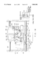
- FIG. 9 is a diagram showing the structure of the foregoing apparatus for switching the optical path.
- the switching apparatus is arranged to insert/remove the three optical devices into/from a corresponding position of the two switching positions in the optical system shown in FIG. 8, that is, the deflection prism 22, bending prism 23 and the correction prism 23A are switched by the switching apparatus.
- FIG. 9 illustrates a state where the reflection prism 22 has been removed from an observation optical path 104 and the bending prism 23 has been inserted into the observation optical path 104.
- FIG. 10 is a diagram showing the apparatus for switching the optical path for an optical microscope in a state where the deflection prism 22 and the bending prism 23 have been inserted into the optical path 104.
- reference numeral 102 represents a holding member for holding the deflection prism 22.
- Reference numeral 103 represents a guide rod for holding the holding member 102 in such a manner that the deflection prism 22 can arbitrarily be inserted or removed to and from the observation optical path 104.
- Reference numeral 23 represents a bending prism
- 23A represents a correction prism for correcting the length of the optical path
- 107 represents a holding member for holding the bending prism 23 and the correction prism 23A.
- Reference numeral 108 represents a guide rod for supporting the holding member 107 in order to selectively insert or remove the bending prism 23 and the correction prism 23A to and from the observation optical path 104.
- Reference numeral 109 represents a pulse motor and 110 represents a worm gear attached to a shaft of the pulse motor 109.
- Reference numeral 111 represents a worm wheel engaged to the worm gear 110 and having cam grooves 111a and 111b on the side surface thereof.
- Reference numeral 112 represents a first lever having an end 112a received in a cam groove 111a formed on the worm wheel 111, the first lever 112 being arranged to rotate relative to a supporting point 112c to cause another end 112b to urge the holding member 102 through a groove 102a formed in the holding member 102.
- Reference numeral 113 represents a second lever having an end 113a received in a cam groove 111b formed on the worm wheel 111, the second lever 113 being arranged to rotate relative to a supporting point 113c to cause another end 113b to urge the holding member 107 through a groove 107a formed in the holding member 107.
- the cam grooves 111a and 111b on the worm wheel 111 actually form one orbit and partially share a range to be fixed to the ends 112a and 113a of the first and second levers 112 and 113.
- Reference numeral 114 represents a fixing member secured to the holding member 102 and arranged to fix the deflection prism 22 to a predetermined position when the deflection prism 22 is inserted into or removed from the optical path 104.
- Reference numeral 115 represents a slit plate secured to the holding member 102.
- Reference numeral 116 represents a sensor disposed to correspond to the slit plate in order to detect that the holding member 102 has been fixed to a predetermined position.
- a control unit 3 is connected to the sensor 116, the control unit 3 outputs control signal for generating a motor operating pulse based on a sensor signal supplied from the sensor 116 and instruction signal supplied from the control panel 2.
- a drive circuit 3a which is connected to the control unit 3, outputs a motor operating pulse to a pulse motor 109 based on a control signal supplied from control unit 3.
- Reference numeral 117 represents a lens tube body to which the guide rods 103 and 108, the motor 109, the worm wheel 111, the first lever 112 and the second lever 113 are secured.
- optical paths 1, 2 and 3 can be obtained by changing the state of insertion and removal of the deflection prism 22, the bending prism 23 and the correction prism 23A to and from the observation optical path 104.
- the optical path 1 is, as shown in FIG. 10, an optical path formed when the deflection prism 22 and the bending prism 23 have been inserted into the optical path 104.
- the bending prism 23 shown in FIG. 10 may be disposed in the optical path 104 or removed from the same because all of light beams are directed to the ocular lenses 33a and 33b by the deflection prism 22.
- the optical path 2 is, as shown in FIG. 9, formed in a state where the deflection prism 22 has been removed from the optical path 104 and the bending prism 23 has been inserted into the optical path 104.
- the following state corresponds to the optical path 2: a state where the deflection prism 22 has been removed from the optical path and the bending prism 23 has been inserted into the optical path in the structure shown in FIG. 8 so that a loop optical path has been formed.
- light from the objective lens 21 is bent substantially perpendicularly by the bending prism 23, and then allowed to pass through the loop optical path, and then returned to the bending prism 23 so as to be bent substantially perpendicularly and introduced into the TV camera.
- light is directed to the ocular lenses 33a and 33b at an intermediate position of the loop optical path by the reflecting member or the beam splitter 31 shown in FIG. 8.
- the optical path 3 is formed when the deflection prism 22 has been removed from the optical path 104 and the correction prism 23A has been inserted into the optical path 104.
- the foregoing state corresponds to a state where the following elements shown in FIG. 8 are moved as follows: the deflection prism 22 has been removed from the optical path, the bending prism 23 has been removed from the bending prism 23 and the correction prism 23A has been inserted into the optical path so that light from the objective lens 21 is as it is introduced into the TV optical path through the correction prism 23A.
- a cam and lever mechanism for forming the optical paths 1 to 3 will now be described with reference to FIGS. 12A to 12C.
- the first lever 112 rotates by an angular degree required for the end 112b drives the deflection prism 22.
- the first lever 112 is not rotated because the end 112a moves on to a track formed by the cam groove of the worm wheel 111 and having a predetermined radius with respect to the center of rotation.
- the second lever 113 is applied with the force from the wall surface 111a of the cam groove to start rotating around the supporting point 113c.
- the second lever 113 is rotated for an angular degree required for the end 113b to drive the bending prism 23 and the correction prism 23A.
- optical path 1 is initially set.
- Rotation of the worm wheel 111 causes the first lever 112 having the end 112a received in the cam groove 111a formed on the side surface of the worm wheel 111 to be also rotated around the supporting point 112c.
- Rotation of the first lever 112 is, at the end 112b thereof, converted into linear motion by the groove 102a formed in the holding member 102.
- the holding member 102 starts moving along the guide rod 103.
- the holding member 102 When the holding member 102 has been moved to a predetermined position, that is, a position at which the deflection prism 22 has been removed from the optical path 104, the slit plate 115 secured to the holding member 102 is ejected from a detection range for the sensor 116.
- control unit 3 In response to a sensor signal supplied from the sensor 116 at this time, the control unit 3 detects that the deflection prism 22 has been moved to a predetermined position so that the control unit 3 supplies an interruption signal to the pulse motor 109.
- the fixing member 114 is received by the V-groove 103a formed in the guide rod 103 so that the holding member 102 and the deflection prism 22 held by the holding member 102 are stopped at the removal positions from the optical path 104.
- the foregoing state corresponds to the state of the optical path 2 shown in FIG. 9.
- the detection to be performed by the control unit 3 that the slit plate 115 has been removed from the detection range for the sensor 116 is stored as a pulse of the pulse motor 109. Then, a predetermined number of pulses, the reference of which is the foregoing pulse, are supplied to the pulse motor 109 so that switching to all of the optical paths is performed.
- a modification of the first embodiment may be employed in which another cam groove is formed in the reverse surface of the worm wheel 111 and the optical device holding member holding the beam splitter 31 shown in FIG. 8 is connected to a lever.
- the beam splitter 31 can be moved by the pulse motor 109.
- an optical path as shown in FIG. 13 is formed.
- the apparatus for switching the optical path for an optical microscope is able to switch the two switching portions, that is, the switching portion of the deflection prism 22 and the switching portion of the bending prism 23 and the correction prism 23A by one motor and one sensor without the necessity of providing plural actuators and sensors. Therefore, the structure of the drive system can be simplified and the cost of the optical microscope can be reduced.
- the foregoing embodiment has been described about the switching apparatus for switching the optical devices at two or three switching positions, the foregoing structure may, of course, be applied to a structure having four or more switching portions.
- FIG. 14 is a diagram of an apparatus for switching the optical path for an optical microscope according to a second embodiment of the present invention.
- the apparatus for switching the optical path for an optical microscope has characteristics that an end 112b of a first lever 112 and a groove portion of a holding member 102 are fixed with a predetermined movable amount.
- the apparatus for switching the optical path for an optical microscope has a structure such that introduction of the fixing member 114 secured to the holding member 102 into the inclined portion of a predetermined position 103a formed in the guide rod 103 results in introduction of the fixing member 114 toward a predetermined position being commenced and simultaneously the slit plate 115 being ejected from the detection range for the sensor 116.
- the holding member 102 Since the speed, at which the holding member 102 is introduced into the stoppage position due to the introducing force of the fixing member 114, is higher than the speed at which the holding member 102 is moved by the first lever 112, the holding member 102 is removed from the urging force of the first lever 112 and slightly earlier introduced into the stoppage position.
- the pulse motor 109 continues rotating during this, and then stops when the pulse motor 109 has transmitted a predetermined number of pulses counted from detection performed by the sensor 116. That is, the control unit 103 interrupts transmission of the motor operation pulse to the pulse motor 109 after a predetermined period of time has passed from detection of introduction of the fixing member 114 into the inclined portion of the V-groove 103a by the sensor 116.
- the position, at which the worm wheel 111 is stopped, is arranged to accurately correspond to a predetermined angle of rotation required to switch the deflection prism 22.
- the apparatus for switching the optical path for an optical microscope has the structure such that the holding member 102 is introduced into the predetermined position 103a by the fixing member 114 earlier than stoppage of the pulse motor 109 by the period of time corresponding to a predetermined number of pulses. Therefore, the operation for switching the holding member 102 and the deflection prism 101 can be performed without any error occurring in the angle of rotation of the worm wheel 111 having the cam grooves 111a and 111b formed therein.
- the apparatus for switching the optical path for an optical microscope according to this embodiment is characterized in that two fixing mechanisms having different introducing ranges are employed.
- the residual structures are the same as those of the apparatus for switching the optical path for an optical microscope according to the second embodiment.
- FIG. 16 is a top view showing the structures of the fixing mechanisms of the apparatus for switching the optical path for an optical microscope according to this embodiment.
- the holding member 200 for holding the optical device is supported by two guide rods 201 and 202.
- Each of the guide rods 201 and 202 has grooves 205 and 206 having different introducing ranges.
- Reference numerals 203 and 204 represent fixing members for fixing the holding member 200 to grooves 205 and 206 formed in each of the guide rods 201 and 202.
- introducing force is initially generated by the groove 206 formed in the guide rod 201 and having a wide introducing range and the fixing member 203.
- the holding member 200 When the holding member 200 has further approached the stoppage position, the holding member 200 is introduced into the stoppage position by the groove 205 formed in the guide rod 202 and having a small introducing range and the fixing member 204.
- FIG. 17A is a graph showing the relationship between the introducing force of the groove 206 formed in the guide rod 201 and having a wide introducing range and the position of the fixing member 204. As shown in FIG. 17A, the introducing force is zero when the fixing member 204 is positioned at the central position (the stoppage position) of the groove 206. In the inclined portion, a moderate introducing force is generated.
- FIG. 17B is a graph showing the relationship between the introducing force of the groove 205 formed in the guide rod 202 and having a small introducing range and the position of the guide rod 202. As shown in FIG. 17B, the introducing force is made to be maximum when the fixing member 204 is positioned at the central position (the stoppage position) of the groove 206.
- FIG. 17C is a graph showing a result of composition of the introducing force shown in FIG. 17A and that shown in FIG. 17B.
- the structure in which the introducing ranges of the grooves formed in the two guide rods 201 and 202 for supporting the holding member are made to be different from each other, enables introducing range d' to be widened.
- the apparatus for switching the optical path for an optical microscope enables the introducing range to be widened. Therefore, the optical paths can reliably be switched even if the manufacturing accuracy of each of the cam grooves 111a and 111b and the levers 112 and 113 are unsatisfactory.
- grooves having different introducing ranges are formed in the two guide rods 201 and 202 for supporting the holding member 200
- three or more guide rods for supporting the optical device holding member 200 may be provided.
- grooves having different introducing ranges may be formed in each of the guide rods in the foregoing case.
- the apparatus for switching the optical path for an optical microscope is characterized in that a screw portion is formed in a portion of the lens tube body and a pin is screwed in the screw portion so as to lock the holding member.
- FIG. 18 is a diagram showing the structure of a transportation locking apparatus for the apparatus for switching the optical path for an optical microscope according to this embodiment.
- the same elements as those shown in FIG. 9 are given the same reference numerals and the same elements are omitted from description. The description will be performed about only different portions.
- the screw portion 211 is formed in a portion of the lens tube body 117.
- the pin 212 having a screw groove formed in a portion of the body thereof is screwed in the screw hole 211.
- the pin 212 is not used in a normal operation in which two switching portions are operated by the pulse motor 109.
- the pulse motor 109 rotates so that the worm wheel 111 rotates clockwise, when viewed in FIG. 18, through the worm gear 110.
- Rotation of the worm wheel 111 causes the first lever 112 having an end received in the cam groove 111a formed on the side surface of the worm wheel 111 to be also clockwise rotated around the supporting point 112c of the first lever 112.
- Rotation of the first lever 112 is, at the end 112b thereof, converted into linear motion in the groove 102a formed in the holding member 102.
- the holding member 102 starts moving along the guide rod 103.
- the holding member 102 When the holding member 102 has been moved to a predetermined position, that is, a position at which the deflection prism 22 is removed from the optical path 104, the slit plate 115 secured to the holding member 102 is removed from the sensing range for the sensor 116. Thus, detection performed by the sensor 116 results in an instruction to interrupt rotation of the pulse motor 109 to be issued.
- the fixing member 114 is received by the V-groove 103a formed in the guide rod 103 so that the holding member 102 and the deflection prism 22 held by the holding member 102 are stopped at positions removed from the optical path 104.
- the optical devices can easily and quickly be secured in such a manner that dust proof in the apparatus and the optical accuracy of each optical device is maintained.
- a transportation locking apparatus for the apparatus for switching the optical path for an optical microscope according to a fifth embodiment of the present invention will now be described.
- FIG. 19 is a diagram showing the structure of the transportation locking apparatus for the apparatus for switching the optical path for an optical microscope according to the fifth embodiment of the present invention.
- the same elements as those shown in FIG. 9 are given the same reference numerals and the same elements are omitted from illustration. The description will be performed about only different portions.
- the transportation locking apparatus for the apparatus for switching the optical path for an optical microscope is characterized in that a pin 221 is automatically and inserted by the holding member 102.
- reference numeral 117b represents a portion of the lens tube having a through hole, into which the pin 221 is inserted.
- a leading end 222a of the lever 222 is connected to an end 221a of the pin 221.
- the lever 222 is able to rotate around a shaft 222c and has another end 222b connected to a shaft of a solenoid 223. Moreover, a spring 224 is attached to a position adjacent to the end 222a of the lever 222.
- the solenoid 223 is connected to a power source 220 of the apparatus for switching the optical path so that electric power is supplied when the power source 220 of the apparatus for switching the optical path has been turned on.
- the solenoid 223 is supplied with electric power so that the lever 222 is rotated due to the attracting force of the solenoid 223.
- the end 221b is removed from the groove 102a of the holding member 102 so that the state where the optical device holding member 102 is suspended.
- the force of the spring 224 urges the pin 221 to be movably received in the groove 102a of the holding member 102. As a result, movement of the optical device holding member 102 is prevented.
- the transportation locking apparatus for the apparatus for switching the optical path for an optical microscope has the structure such that switching of the optical devices is automatically locked when the power source is turned on or off.
- a complicated operation of locking the optical device when an optical microscope is transported can be omitted.
- the mechanism can be protected from being damaged due to an impact taking place during transportation.
- FIG. 20 is a cross sectional view showing a transportation locking apparatus for the apparatus for switching the optical path for an optical microscope according to a sixth embodiment of the present invention.
- FIG. 21 is a side view showing the transportation locking apparatus for the apparatus for switching the optical path for an optical microscope according to this embodiment.
- Optical devices 231 which are prisms of two types, are secured to an optical device holding member 232.
- the optical device holding member 232 has a groove formed in the lengthwise direction of the apparatus. When the groove and a guide rod 233 are slid mutually, the optical device holding member 232 is moved to the right or left.
- the optical device holding member 232 has a groove 234 formed in a direction perpendicular to the lengthwise direction of the apparatus.
- the groove 234 is arranged to receive an arm 236 to which a bearing 235 is attached.
- the width of the groove 234 is made to be slightly larger than the diameter of the bearing 235 to permit a play so that the bearing 235 is always brought into contact with one surface of the groove when the moving direction is changed.
- the arm 236 is rotated around a supporting point 237 when the bearing adjacent to the cam 238 traces a cam groove formed in the cam 238.
- the optical device holding member 232 is pushed by the bearing 235 and moved. If the overall body of the apparatus is vibrated during transportation or the like, the optical device holding member 232 is moved to the right and left so that the bearing 235 is applied with a load in an opposite direction of the movement of the optical device holding member 232.
- a screw hole 241a is formed in a cover 240, which is fixed on a casing 239; and a fixing screw 241 having a screw portion in a portion of the body thereof is screwed in the screw hole 241a.
- the leading end of the fixing screw 241 is rounded and the diameter of the leading end of the same is made to be slightly smaller than the width of the groove 234.
- the groove for receiving the fixing screw 241 may be formed individually from the groove for transmitting the driving force.
- the transportation locking apparatus for the apparatus for switching the optical path for an optical microscope is able to prevent loads being applied to the bearing 235 during transportation. Thus, breakage of the apparatus for switching the optical path can be prevented.
- the foregoing mechanism can easily be realized by simply forming the screw hole 241a in the cover 240 and by manufacturing the fixing screw 241. Since only the diameter of the leading end of the fixing screw 241 is required to meet a predetermined accuracy, the cost can significantly be reduced.
- FIG. 22A is a front side showing the structure of a transportation locking apparatus for a magnifying power changing apparatus of an optical microscope according to a seventh embodiment of the present invention.
- the magnifying power changing apparatus for an optical microscope shown in FIG. 22A comprises a lens of a zoom optical system for moving the lens.
- FIG. 22B is a front view showing the transportation locking apparatus for the magnifying power changing apparatus according to this embodiment.
- FIG. 22C is a bottom view taken along an arrow shown in FIG. 22B and showing the transportation locking apparatus for the magnifying power changing apparatus according to this embodiment.
- Reference numeral 241a represents a lens of a zoom optical system.
- the lens 241a is secured to a lens frame 242.
- the lens frame 242 has two openings into which a guide rod 243 is received.
- the lens frame 242 slides and moves along the guide rod 243.
- a shaft 246 for holding a bearing 245 which rolls along a cam groove of the rod cam 244 is fastened to the lens frame 242.
- an L-shape restricting member 248 is inserted into a rectangular through hole 247a previously formed in the bottom surface of a casing 247. Then, a U-shape groove formed at the leading end of the restricting member 248 is fitted to the outer shape of the shaft 246. Then, the restricting member 248 is secured from outside by a screw 248a.
- the shaft 246 of the lens frame 242 forming a portion of the optical device holding member is fixed by the restricting member 248 so that the movement of the lens frame 242 in the moving direction is prevented.
- the sixth and seventh embodiments have the structure such that the bearing is required to be stopped at the center of the groove in such a manner that the contact of the groove wall with the bearing is prevented.
- the transportation locking apparatus for the magnifying power changing apparatus for an optical microscope has the structure such that insertion of the restricting member 248 from outside causes the shaft 246 of the lens frame 242 to be fixed so as to prevent movement in the moving direction, the optical device can easily be locked to prevent movement.
- FIG. 23 is a schematic view showing a transportation locking apparatus for an optical microscope according to an eighth embodiment of the present invention.
- FIG. 24 is an enlarged view showing a transportation locking mechanism of the transportation locking apparatus for an optical microscope according to this embodiment.
- FIGS. 23 and 24 show a magnifying power changing mechanism for a zoom optical system having a cylindrical cam.
- the bearing 253 is connected to a lens frame 255 through a shaft 254.
- the lens frame 255, to which lens 255a is secured, is vertically moved along a guide rod 256.
- a fixing screw 258 having a screwed groove in a portion of the body thereof is threaded in a screw hole formed in a casing 257 to insert the bearing 253 into a receiving hole 261 formed to receive the bearing 253 formed at the leading end of the fixing screw 258.
- the bearing 253 is allowed to slightly upwards float on the surface of the cam.
- the surface of the cam can be protected from being damaged.
- the locking means such as the fixing screw, is removed from outside when a user uses the apparatus.
- the dust proofing characteristic in the apparatus can be maintained by attaching a cap or a seal to the hole in the casing.
- the movable elements such as the lens frame and the optical device holding member, can easily and roughly be located by an electrical sequence in the case of an electric drive structure.
- a locking mechanism with respect to a predetermined position can be designed such that a click position or the like is used.
- an apparatus for switching the optical path for the optical microscope having a simple structure, exhibiting a low cost and permitted to be operated easily can be provided for a microscope of the type having a plurality of optical-device switching portions and arranged to obtain a required optical path by switching the switching portion while relating the switching portions to one another.
- a transportation locking apparatus for an optical-path switching apparatus for an optical microscope can be provided which is not broken due to impact during transportation and which always enables reliable switching to be performed.
- An apparatus for switching the optical path for an optical microscope can be provided with which the transportation locking mechanism can easily and quickly be attached and detached from outside by a user while maintaining dust proofing characteristic and accuracy of the optical devices.
Landscapes
- Physics & Mathematics (AREA)
- Chemical & Material Sciences (AREA)
- Analytical Chemistry (AREA)
- General Physics & Mathematics (AREA)
- Optics & Photonics (AREA)
- Engineering & Computer Science (AREA)
- Multimedia (AREA)
- Microscoopes, Condenser (AREA)
Applications Claiming Priority (4)
| Application Number | Priority Date | Filing Date | Title |
|---|---|---|---|
| JP15762795 | 1995-06-23 | ||
| JP7-157627 | 1995-06-23 | ||
| JP7-177485 | 1995-07-13 | ||
| JP7177485A JPH0968656A (ja) | 1995-06-23 | 1995-07-13 | 光学顕微鏡の光路切換装置 |
Publications (1)
| Publication Number | Publication Date |
|---|---|
| US5861982A true US5861982A (en) | 1999-01-19 |
Family
ID=26485013
Family Applications (1)
| Application Number | Title | Priority Date | Filing Date |
|---|---|---|---|
| US08/663,668 Expired - Lifetime US5861982A (en) | 1995-06-23 | 1996-06-14 | Optical-path switching apparatus, optical-device switching apparatus for optical microscope and locking apparatus for use in transporting optical microscope |
Country Status (2)
| Country | Link |
|---|---|
| US (1) | US5861982A (ja) |
| JP (1) | JPH0968656A (ja) |
Cited By (12)
| Publication number | Priority date | Publication date | Assignee | Title |
|---|---|---|---|---|
| US6088155A (en) * | 1996-06-04 | 2000-07-11 | Carl Zeiss Jena Gmbh | Device for switching the operating modes of a microscope tube |
| US20020181095A1 (en) * | 1996-10-24 | 2002-12-05 | Leica Microsystems Wetzlar Gmbh | Microscope with a proximity sensor |
| US6563113B1 (en) * | 1997-09-05 | 2003-05-13 | Leica Microsystems (Schweiz) Ag | Microscope, especially a fluorescence microscope, particularly a stereo fluorescence microscope |
| US20040120032A1 (en) * | 2002-11-29 | 2004-06-24 | Ulrich Sander | Stereomicroscope |
| US20040136059A1 (en) * | 2002-11-29 | 2004-07-15 | Ulrich Sander | Stereomicroscope |
| US20060011456A1 (en) * | 2004-07-19 | 2006-01-19 | Leica Microsystems Cms Gmbh | Slider for positioning multiple optical elements, and microscope having a slider for positioning multiple optical elements |
| US20100253912A1 (en) * | 2009-04-01 | 2010-10-07 | Leica Microsystems (Schweiz) Ag | Method for illuminating an object, and a surgical microscope having an illuminating device |
| US20120147462A1 (en) * | 2010-12-10 | 2012-06-14 | Leica Microsystems Cms Gmbh | Microscope stage with pivotable objective holder |
| US20140135581A1 (en) * | 2012-11-14 | 2014-05-15 | Gynius Ab | Portable battery powered self-illuminated multispectral multi-magnification colposcope |
| EP2780753A4 (en) * | 2011-11-15 | 2015-07-15 | Ge Healthcare Biocience Bio Process Corp | MICROSCOPIC LIGHTING SYSTEM WITH SWITCHABLE MODE |
| DE102023130857B3 (de) | 2023-11-07 | 2024-11-21 | Karl Storz Se & Co. Kg | Filterwechselvorrichtung für eine endoskopische Kamera, Kamerakopf für ein Endoskop und Nachrüstsatz zum Nachrüsten eines Kamerakopfes und/oder eines Endoskops |
| US20250231083A1 (en) * | 2024-01-12 | 2025-07-17 | Viavi Solutions Inc. | Multiple magnification inspection of duts |
Families Citing this family (1)
| Publication number | Priority date | Publication date | Assignee | Title |
|---|---|---|---|---|
| JP2009145671A (ja) * | 2007-12-14 | 2009-07-02 | Olympus Corp | 電動顕微鏡 |
Citations (10)
| Publication number | Priority date | Publication date | Assignee | Title |
|---|---|---|---|---|
| US2684611A (en) * | 1952-02-12 | 1954-07-27 | Hinden Fritz | Objective mount with built-in filters |
| US2687669A (en) * | 1951-06-27 | 1954-08-31 | Bolsey Jacques | Motion-picture camera lens and filter turret locking mechanism |
| US3868714A (en) * | 1971-12-17 | 1975-02-25 | Nippon Kogaku Kk | Filter change-over device in an objective lens for a single lens reflex camera |
| JPS5636614A (en) * | 1979-09-04 | 1981-04-09 | Tokyo Optical Co Ltd | Turret type variable power device in lens system |
| US4368947A (en) * | 1979-11-13 | 1983-01-18 | Olympus Optical Co., Ltd. | Turret condenser for microscopes |
| US4544236A (en) * | 1981-11-02 | 1985-10-01 | Olympus Optical Co., Ltd. | Turret |
| JPS6345566A (ja) * | 1986-08-13 | 1988-02-26 | Takaoka Ind Ltd | 課電表示器 |
| US4852955A (en) * | 1986-09-16 | 1989-08-01 | Laser Precision Corporation | Microscope for use in modular FTIR spectrometer system |
| US4961636A (en) * | 1987-03-09 | 1990-10-09 | Ernst Leitz Wetzlar Gmbh | Revolving nose piece for optical components and process for adjusting the number of revolutions thereof |
| US5517353A (en) * | 1993-05-28 | 1996-05-14 | Nikon Corporation | Illuminating apparatus for a microscope |
-
1995
- 1995-07-13 JP JP7177485A patent/JPH0968656A/ja not_active Withdrawn
-
1996
- 1996-06-14 US US08/663,668 patent/US5861982A/en not_active Expired - Lifetime
Patent Citations (10)
| Publication number | Priority date | Publication date | Assignee | Title |
|---|---|---|---|---|
| US2687669A (en) * | 1951-06-27 | 1954-08-31 | Bolsey Jacques | Motion-picture camera lens and filter turret locking mechanism |
| US2684611A (en) * | 1952-02-12 | 1954-07-27 | Hinden Fritz | Objective mount with built-in filters |
| US3868714A (en) * | 1971-12-17 | 1975-02-25 | Nippon Kogaku Kk | Filter change-over device in an objective lens for a single lens reflex camera |
| JPS5636614A (en) * | 1979-09-04 | 1981-04-09 | Tokyo Optical Co Ltd | Turret type variable power device in lens system |
| US4368947A (en) * | 1979-11-13 | 1983-01-18 | Olympus Optical Co., Ltd. | Turret condenser for microscopes |
| US4544236A (en) * | 1981-11-02 | 1985-10-01 | Olympus Optical Co., Ltd. | Turret |
| JPS6345566A (ja) * | 1986-08-13 | 1988-02-26 | Takaoka Ind Ltd | 課電表示器 |
| US4852955A (en) * | 1986-09-16 | 1989-08-01 | Laser Precision Corporation | Microscope for use in modular FTIR spectrometer system |
| US4961636A (en) * | 1987-03-09 | 1990-10-09 | Ernst Leitz Wetzlar Gmbh | Revolving nose piece for optical components and process for adjusting the number of revolutions thereof |
| US5517353A (en) * | 1993-05-28 | 1996-05-14 | Nikon Corporation | Illuminating apparatus for a microscope |
Cited By (21)
| Publication number | Priority date | Publication date | Assignee | Title |
|---|---|---|---|---|
| US6088155A (en) * | 1996-06-04 | 2000-07-11 | Carl Zeiss Jena Gmbh | Device for switching the operating modes of a microscope tube |
| US20020181095A1 (en) * | 1996-10-24 | 2002-12-05 | Leica Microsystems Wetzlar Gmbh | Microscope with a proximity sensor |
| US6738558B2 (en) * | 1996-10-24 | 2004-05-18 | Leica Microsystems Wetzlar Gmbh | Microscope with a proximity sensor |
| US6563113B1 (en) * | 1997-09-05 | 2003-05-13 | Leica Microsystems (Schweiz) Ag | Microscope, especially a fluorescence microscope, particularly a stereo fluorescence microscope |
| US20040120032A1 (en) * | 2002-11-29 | 2004-06-24 | Ulrich Sander | Stereomicroscope |
| US20040136059A1 (en) * | 2002-11-29 | 2004-07-15 | Ulrich Sander | Stereomicroscope |
| US6982825B2 (en) * | 2002-11-29 | 2006-01-03 | Leica Microsystems (Schweiz) Ag | Stereomicroscope |
| US7206127B2 (en) * | 2002-11-29 | 2007-04-17 | Leica Microsystems (Schweiz) Ag | Stereomicroscope |
| DE102004034844B4 (de) * | 2004-07-19 | 2011-07-28 | Leica Microsystems CMS GmbH, 35578 | Schieber zum Positionieren mehrerer optischer Elemente und Mikroskop mit Schieber zum Positionieren mehrerer optischer Elemente |
| US20060011456A1 (en) * | 2004-07-19 | 2006-01-19 | Leica Microsystems Cms Gmbh | Slider for positioning multiple optical elements, and microscope having a slider for positioning multiple optical elements |
| US7233436B2 (en) * | 2004-07-19 | 2007-06-19 | Leica Microsystems Cms Gmbh | Slider for positioning multiple optical elements, and microscope having a slider for positioning multiple optical elements |
| US20100253912A1 (en) * | 2009-04-01 | 2010-10-07 | Leica Microsystems (Schweiz) Ag | Method for illuminating an object, and a surgical microscope having an illuminating device |
| US7967441B2 (en) * | 2009-04-01 | 2011-06-28 | Leica Microsystems (Schweiz) Ag | Method for illuminating an object, and a surgical microscope having an illuminating device |
| US20120147462A1 (en) * | 2010-12-10 | 2012-06-14 | Leica Microsystems Cms Gmbh | Microscope stage with pivotable objective holder |
| US8559119B2 (en) * | 2010-12-10 | 2013-10-15 | Leica Microsystems Cms Gmbh | Microscope stage with pivotable objective holder |
| EP2780753A4 (en) * | 2011-11-15 | 2015-07-15 | Ge Healthcare Biocience Bio Process Corp | MICROSCOPIC LIGHTING SYSTEM WITH SWITCHABLE MODE |
| US9507136B2 (en) | 2011-11-15 | 2016-11-29 | Ge Healthcare Bio-Sciences Corp. | Mode-switchable illumination system for a microscope |
| US20140135581A1 (en) * | 2012-11-14 | 2014-05-15 | Gynius Ab | Portable battery powered self-illuminated multispectral multi-magnification colposcope |
| DE102023130857B3 (de) | 2023-11-07 | 2024-11-21 | Karl Storz Se & Co. Kg | Filterwechselvorrichtung für eine endoskopische Kamera, Kamerakopf für ein Endoskop und Nachrüstsatz zum Nachrüsten eines Kamerakopfes und/oder eines Endoskops |
| EP4552547A1 (de) * | 2023-11-07 | 2025-05-14 | Karl Storz SE & Co. KG | Filterwechselvorrichtung für eine endoskopische kamera, kamerakopf für ein endoskop und nachrüstsatz zum nachrüsten eines kamerakopfes und/oder eines endoskops |
| US20250231083A1 (en) * | 2024-01-12 | 2025-07-17 | Viavi Solutions Inc. | Multiple magnification inspection of duts |
Also Published As
| Publication number | Publication date |
|---|---|
| JPH0968656A (ja) | 1997-03-11 |
Similar Documents
| Publication | Publication Date | Title |
|---|---|---|
| US5861982A (en) | Optical-path switching apparatus, optical-device switching apparatus for optical microscope and locking apparatus for use in transporting optical microscope | |
| US5943169A (en) | Image blur preventing device | |
| US5416558A (en) | Camera with shake preventing apparatus | |
| US6563634B2 (en) | Microscope with aberration correcting function | |
| US5715482A (en) | Collapsible type zoom camera | |
| US5510937A (en) | Apparatus for adjusting intermeshing angle in feed screw mechanism | |
| US5745800A (en) | Camera shake compensation device | |
| US5844719A (en) | Light deflection apparatus | |
| JPH0149921B2 (ja) | ||
| US6225613B1 (en) | Optical device provided with correcting function for trembling of focused image with a stop of power supply to the device | |
| JPH1062674A (ja) | 双眼鏡 | |
| US6043934A (en) | Observing equipment having hand-vibration compensation system | |
| US6208464B1 (en) | Tremble preventing device | |
| JP3869660B2 (ja) | 像振れ補正装置および像振れ補正機能付き光学機器 | |
| US5673149A (en) | Optical apparatus having a function of preventing image blur or shake and having lens barrels of different diameters | |
| US5930042A (en) | Optical lens barrel with an optical lens group shiftable perpendicular to and parallel with an optical axis and method of use | |
| US6018420A (en) | Binocular having hand-vibration compensation system | |
| JPH0743645A (ja) | 観察用光学機器 | |
| US20050231798A1 (en) | System microscope | |
| CN100440026C (zh) | 光学仪器 | |
| US6057962A (en) | Observation optical system having hand-vibration compensation system | |
| US5715479A (en) | Blur prevention device for preventing image blur | |
| EP0665473B1 (en) | Zoom lens device | |
| US6067195A (en) | Binoculars having hand-vibration compensation system | |
| US6266190B1 (en) | Optical device provided with correcting function for trembling of focused image |
Legal Events
| Date | Code | Title | Description |
|---|---|---|---|
| AS | Assignment |
Owner name: OLYMPUS OPTICAL CO., LTD., JAPAN Free format text: ASSIGNMENT OF ASSIGNORS INTEREST;ASSIGNORS:TAKAHAMA, YASUTERU;KARAKI, KENJI;REEL/FRAME:008051/0735 Effective date: 19960610 |
|
| FEPP | Fee payment procedure |
Free format text: PAYOR NUMBER ASSIGNED (ORIGINAL EVENT CODE: ASPN); ENTITY STATUS OF PATENT OWNER: LARGE ENTITY |
|
| STCF | Information on status: patent grant |
Free format text: PATENTED CASE |
|
| FPAY | Fee payment |
Year of fee payment: 4 |
|
| FPAY | Fee payment |
Year of fee payment: 8 |
|
| FPAY | Fee payment |
Year of fee payment: 12 |