US5878979A - Method and apparatus for landing a wing - Google Patents
Method and apparatus for landing a wing Download PDFInfo
- Publication number
- US5878979A US5878979A US08/552,160 US55216095A US5878979A US 5878979 A US5878979 A US 5878979A US 55216095 A US55216095 A US 55216095A US 5878979 A US5878979 A US 5878979A
- Authority
- US
- United States
- Prior art keywords
- wing
- line
- parachute
- deployment
- release mechanism
- Prior art date
- Legal status (The legal status is an assumption and is not a legal conclusion. Google has not performed a legal analysis and makes no representation as to the accuracy of the status listed.)
- Expired - Lifetime
Links
Images


Classifications
-
- B—PERFORMING OPERATIONS; TRANSPORTING
- B64—AIRCRAFT; AVIATION; COSMONAUTICS
- B64C—AEROPLANES; HELICOPTERS
- B64C31/00—Aircraft intended to be sustained without power plant; Powered hang-glider-type aircraft; Microlight-type aircraft
- B64C31/028—Hang-glider-type aircraft; Microlight-type aircraft
- B64C31/0285—Safety devices
-
- B—PERFORMING OPERATIONS; TRANSPORTING
- B64—AIRCRAFT; AVIATION; COSMONAUTICS
- B64D—EQUIPMENT FOR FITTING IN OR TO AIRCRAFT; FLIGHT SUITS; PARACHUTES; ARRANGEMENT OR MOUNTING OF POWER PLANTS OR PROPULSION TRANSMISSIONS IN AIRCRAFT
- B64D17/00—Parachutes
- B64D17/80—Parachutes in association with aircraft, e.g. for braking thereof
Definitions
- the present application relates to a wing and especially to an improved method and apparatus for landing a wing.
- Hang gliders allow manned flight without the expense or restrictions of powered flight. These gliders are aerodynamically designed such that their lift-to-drag ratio (commonly known as glide ratio) is greater than about 10:1 such that the glider is capable of suspending a flyer for several hours under the proper atmospheric conditions.
- Hang glider designs range from the popular delta wing design commonly known as a Rogallo wing and intermediate gliders with glide ratios of about 10:1 with docile characteristics to competition gliders with glide ratios as high as 13:1, but with less stable characteristics.
- the original Rogallo wing (about 45° sweep) had a glide ratio of about 4:1, and modem Rogallo wings (about 30° sweep) have a glide ratio of about 10:1.
- the Rogallo wing design largely resembles a traditional kite with a keel, cross members, and diverging leading edge members.
- Another hang glider design generally similar to the Rogallo wing is disclosed in U.S. Pat. No. 4,116,406 which issued to Hamilton on Sep. 26, 1978.
- This glider has a double surface fabric airfoil forming an envelope, disposed around a Rogallo frame. This airfoil is inflated during flight as air enters an opening in the nose and exhausts through nozzles in the underside along the trailing edge. Inflating the wing improves its lift at lower air speeds.
- This hang glider is manually controlled via a weight shift control bar by a flyer harnessed to the glider and is only usefull for manned flights and not for operations such as air drops of food, supplies, etc., where manned flights are either too dangerous or impossible.
- This hang glider comprises a wing which includes leading edge members, a keel and cross members in a traditional delta wing design.
- the wing further includes upper and lower flexible membranes, a first connector for attaching the upper flexible membrane to the upper aft section of the leading edge member and a second connector for attaching the lower flexible membrane to the lower aft section of the leading edge member.
- the flexible membranes are also joined together rearwardly of the leading edge member.
- At least one of the first and second connectors includes a track for receiving a member carried by one of the flexible membranes. The member cooperates with the track to attach the flexible membrane to the leading edge member.
- the leading edge members are also capable of being pivoted inwardly toward the keel to collapse the wing.
- Parachutes on the other hand, can and have been utilized for air drops of food, supplies, etc., in remote locations where landing an airplane is either impossible or dangerous. Although these parachutes are useful in reducing the ground impact of the dropped load, it is difficult to ensure the parachute reaches the targeted area. Depending upon the precise parachute release time, the atmospheric conditions during release and flight, and release altitude, the parachute may either reach its target or drift up to about 15 miles or more off course.
- Patent application Ser. No. 08/156,322. (Issued as U.S. Pat. No. 5,474,257) which is commonly assigned and is hereby incorporated by reference, discloses a deployable wing comprising a double membrane fabric sail having an upper section disposed above and joined to a lower section, the sail having a leading edge with a front point, a trailing edge, and wing tips.
- the deployable wing further includes an internal structure disposed between the upper section and the lower section, the internal structure having two leading edge spars with a first end and a second end, said first ends pivotally connected together at approximately the front point, a keel spar connected to and disposed between the leading edge spars at the front point and extending rearward toward the trailing edge, and at least two cross spars pivotally attached to both the leading edge spars and a sliding mechanism which traverses along the keel.
- the wing also includes a plurality of fabric ribs disposed between and connected to the upper section and the lower section, the fabric ribs defining the shape of the fabric sail when inflated and have at least one slot through which the cross spars extend from the keel spar to the leading edge spars and ribs; and a ram air intake located on said leading edge at the stagnation point of the wing which inflates the wing during operation.
- the deployable wing attains a glide ration up to or exceeding about 12:1, and greater than 8:1 with typical payloads of about 1,000 lbs. for a 30 ft. wing.
- the wing disclosed in application U.S. Pat. No. 5,474,257 is remotely controllable, allowing for both unmanned flight and accuracy in reaching a targeted area thereby making the wing useful for article recovery and delivery.
- the deployable wing is, however, the first of its type and it has been found that an improved apparatus and method for landing of such a wing is desired.
- the present application therefore provides an improved apparatus and method for landing of a wing, preferably by parachutes.
- the present application relates to a deployable wing including a fabric sail having an upper section joined to a lower section, an air intake opening and an internal structure disposed substantially between the upper section and the lower section.
- the internal structure includes at least two leading edge spars joined at a first end, a keel adjacent to and disposed substantially between the leading edge spars and at least two cross spars pivotally attached to the leading edge spars and the keel.
- the wing further includes a kingpost attached to and extending from the keel, a cargo pod mounted to the wing via the keel and a parachute deployment system.
- the parachute deployment system includes at least one parachute attached to the wing, where deployment of the parachute causes the wing to decelerate in a controlled fashion and descend in a primarily vertical direction to land.
- FIG. 1 is a perspective view, partially broken away, of one embodiment of the deployable wing of the present application illustrating the parachute deployment system and secondary release mechanism, prior to deployment of the landing parachutes.
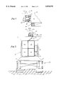
- FIG. 2 is an enlarged view of the secondary release mechanism of FIG. 1.
- FIG. 3 is a side view, in partial cross-section, illustrating the secondary release mechanism of FIG. 2.
- FIG. 4 is a partial side view of the cargo pod according to the present application, partially broken away to show the parachute deployment system.
- FIG. 5 is a rear view of the embodiment of FIG. 4.
- FIG. 6 is a perspective view, partially broken away, of one embodiment of the deployable wing of the present application illustrating the parachute deployment system and secondary release mechanism, immediately after deployment of the landing parachutes.
- FIG. 7 is a perspective view, partially broken away, of one embodiment of the deployable wing of the present application illustrating the parachute deployment system and secondary release mechanism, after deployment of the landing parachutes is complete.
- FIG. 8 illustrates the operation of the wing according to the present application.
- FIG. 1 illustrates a perspective view, partially broken away, of one embodiment of the deployable wing 10 of the present application.
- wing 10 includes a fabric sail 12 defining a leading edge 14 and a trailing edge 16.
- Fabric sail 12 preferably includes an upper section 12a substantially joined along its perimeter to a lower section (not shown) and a plurality of fabric ribs (not shown) connected to the upper and lower sections of the fabric sail. Joining the upper and lower sections forms an envelope which can be filled with air through a ram air intake 20 preferably located at the foremost point of the wing.
- fabric sail 12 further includes an integral cover 13 comprising a first section 13a and a second section 13b, each of which is disposed along the leading edge of wing 10 as shown in FIG. 1.
- First and second sections 13a, 13b each further include complimentary zipper members 15a, 15b which matingly engage in a conventional manner to contain fabric sail 12 within the integral cover as described hereinbelow.
- cover 13 is preferably made of dacron fabric while zipper members 15a, b are of a sufficiently high strength and durability to operate under deployment conditions, although other materials may be utilized depending upon the design configurations of the wing.
- wing 10 further includes an internal structure comprising two leading edge spars (not shown), two cross-spars 22a, 22b, a keel 24, a kingpost 26 and a control device, such as elevon struts 28a, 28b.
- the leading edge spars are pivotally attached at one end between faceplates 17a and 17b to form foremost point 21. Pivotally connected to the leading edge spars at a second end thereof are elevon struts 28a, 28b.
- Keel 24 is mounted at a first end between faceplates 17a, 7b, is mounted at an opposite end between rear plate members 27a, b and is disposed between the leading edge spars.
- Cross spars 22a, 22b each include an outboard end which is pivotally attached to a corresponding leading edge spar and further include inboard ends, opposite the outboard ends, which are pivotally attached to keel 24, preferably via a common slider 80.
- Kingpost 26 is also preferably mounted to keel 24 via the common slider. When erected, kingpost 26 extends substantially perpendicular to keel 24, through an opening in fabric sail 12, to provide an upper attachment point for wires 31a, 31b which support the wing on landing and when the wing experiences negative loads or inverted flight.
- kingpost 26 is pivotally attached to slider 80 such that linear movement of the slider in the direction of arrow "A" along keel 24 causes kingpost 26 to erect through the fabric sail, substantially perpendicular to the keel as shown in FIG. 1.
- the leading edge spars and cross spars are preferably pivotally mounted such that in a closed or pre-deployed position the leading edge spars and cross spars 22a, 22b rest substantially parallel to keel 24.
- the common slider is preferably disposed adjacent the foremost point 21 and kingpost 26 is preferably disposed adjacent and substantially parallel to keel 24, within fabric sail 12.
- complimentary zipper members 15a, 15b are matingly engaged in a conventional manner to contain fabric sail 12 within the integral cover.
- the leading edge spars, cross spars, keel, elevon struts, kingpost and wing tips 29a, b are all substantially disposed within fabric sail 12 in the closed position.
- each leading edge spar is dependent upon the desired size of wing 10, which is only limited by practical considerations: size once folded, desired cruise speed, weight of the payload, etc. Once opened, or deployed, the leading edge spars form an angle therebetween.
- the size of the angle depends upon aerodynamic considerations including aspect ratio, yaw stability, and deployment simplicity, among others. Typically, the angle ranges from about 90° to about 150° with about 105° to about 110° preferred due to simplicity of the deployment mechanism geometry. Angles greater than about 150° result in more complex, and therefore less desirable, mechanical/structural geometry and decreasing yaw stability, while angles less than about 90° result in decreasing glide ratio.
- Yaw stability is where wing sweep allows the wing to tend to maintain its flight directly into the wind, commonly known as maintaining the yaw heading. As the wing yaws, the windward wing tends to drag more than the leeward wing, thereby correcting for the yaw.
- Cross spars 22a, 22b provide structural integrity to the wing 10 by providing strength to the leading edge spars to ensure that in the deployed position the leading spars remain in the open position with the appropriate angle therebetween.
- the distance between the attachment point of the outboard ends to their respective leading edge spars and the inboard ends to the keel determine the length of cross spars 22a, 22b.
- keel 24 similarly provides structural integrity to wing 10 by ensuring that the wing 10 opens to and maintains its full length from the leading edge 14 to the trailing edge 16, commonly known as the wing's chordwise length.
- the length of the keel 24 is substantially equivalent to the chordwise length of the wing at the root (very center line) which, as with the leading edge spars' length, is determined on a practical basis with aeronautical considerations effecting the ultimate size.
- Keel 24 also connects payload pod 50 to wing 10 via mounting member 36.
- the present embodiment also includes elevon struts 28a, 28b which are each connected to a motor or fluid actuator 30a, 30b, the actuators being located externally of fabric sail 12 and mounted to the leading edge spars.
- the motor or actuator is conventional in design and operates to deflect or rotate each elevon struts 28a, 28b independently, out of the plane of the sail, thereby controlling the flight of the wing.
- wing tips 29a, 29b are twisted up or down relative to the leading edge. This helical twisting of the sail results in an aerodynamic force sufficient to pitch or roll the wing.
- Rotating or deflecting the elevon struts in unison generates an aerodynamic force substantially behind the pressure center of the wing which is located at the point about 55% down the keel from the foremost point 16, thereby forming a moment force about the pressure center which is used for pitch control of the wing.
- aerodynamic forces at the wing tips 29a and 29b can be controlled in magnitude and direction, up or down. For example, if the elevon strut 28a is rotated up while elevon strut 28b is rotated down, a downward force is generated on tip 29a and an upward force on tip 29b, resulting in a roll or turn in the direction of strut 28a.
- elevon struts 28a, 28b, or other control devices can be operated with any conventional motor capable of generating sufficient torque to overcome the aerodynamic forces at a speed sufficient for control response.
- Factors important in determining the required torque include wing area, wing loading, aspect ratio, and elevon strut length, among others.
- a wing having a 30 foot wing span, for example, with a sail area of about 190 ft 2 and a 700 lb load requires about 40 to about 80 ft-lb torque while a 15 ft wing span wing with an area of 45 ft 2 and a 90 lb load needs about 15 to about 25 ft-lb torque for control.
- kingpost 26 is approximately 4 ft. which, as with the keel's and leading edge spars' length, is determined on a practical basis with aeronautical considerations effecting the ultimate size.
- kingpost 26 also provides support for strap 32 which is attached at one end between front plate members 33a, 33b, extends over the kingpost and is attached at an opposite end between rear plate members 27a, 27b.
- Strap 32 is of a sufficient length such that when the strap extends over the kingpost and is strapped between plate members 33a, b and 27a, b, there is enough slack present in the strap to allow the strap to be pulled free of the kingpost when parachutes 46 deploy.
- the point at which line 34 attaches to strap 32 is the point at which the wing 10 with cargo pod, or payload 50 will hang substantially horizontal beneath the parachutes without excessive rotation or pitching.
- the length of strap 32 is the length at which the payload will hang substantially horizontal beneath the parachutes. Attachment of line 34 to strap 32 is achieved in the present embodiment through loops which are sewn onto strap 32 and line 34 and which are connected by a clevis fitting, though any conventional method of attachment which will allow for parachute deployment may be utilized.
- Attachment line 34 is joined at an opposite end to parachute deployment system 40 and includes a second line 34a which branches from the attachment line 34 and attaches to a secondary release mechanism 39 disposed within mounting block 38 (FIG. 2).
- Mounting block 38 is connected to wing mounting member 36 which is mounted to both keel 24 and payload pod 50, the mounting member thereby attaching the payload to the wing.
- the secondary release mechanism 39 provides controlled release of parachute deployment system 40 which is described in greater detail below.
- parachute deployment system 40 is substantially disposed with in payload pad 50 and includes an extraction rocket 42 which is connected at one end to a pilot parachute 44, the pilot parachute being connected to a plurality of landing parachutes 46.
- extraction rocket 42 is a compressed air rocket which does not require pyrotechnics and which is available from a number of companies including Second Chanz. Rocket 42 is connected to both the pilot parachute 44 and a rocket deployment system 48.
- the rocket there are preferably three independent deployment systems by which the rocket may be deployed: by a first independent servo motor which is connected to an onboard electronic auto pilot program; by a second, independent servo motor which is signaled by a manual override through a separate radio signal initiated externally of the wing; or by a passive mechanical system which is set to initiate if certain conditions are present and/or if electronic failure has caused either of the servo motors to fail to activate the rocket. All three systems are conventional in design and other systems may be utilized as long as deployment of parachutes 44,46 is achieved.
- the wing's autopilot system which is a conventional design, will be programmed with a predetermined landing site and upon reaching the landing site the autopilot will send a command to the first servo motor to pull a pin attached to the rocket to activate the rocket.
- the servo motor Upon receiving the command from the autopilot the servo motor will activate rocket 42.
- the system is manually overridden by a radio signal from a manned controller, the second servo motor will pull the pin to activate the rocket.
- the third option is the passive mechanical system which is programmed in advance to activate if certain preset conditions are met. In the present embodiment this system is programmed at a minimum altitude limit of 1,000 ft above the ground.
- the rocket will be activated by the mechanical system, which is spring loaded in a conventional manner, pulling the pin attached to the rocket to activate it.
- the mechanical system provides a backup for the servo systems if there is electronic failure either in the onboard electronics or the override system.
- pilot parachute 44 which in the present embodiment is approximately 8 ft. in diameter.
- the pilot parachute is connected by line 33 to landing parachutes 46 which are released by the force of the deployed pilot parachute.
- the number and size of the parachutes used with the deployment system may, however, vary and can be determined by one skilled in the art by taking into consideration the operating conditions of the wing including, but not limited to, the size of the wing, speed at which the wing is traveling, altitude, etc.
- the extraction of the landing parachutes 46 normally occurs at a relatively low altitude, approximately 500 feet or less above the ground at cruise velocity, which for the present embodiment is approximately 60 knots.
- line 34 which is attached to the parachutes extends rearwardly, behind the wing, in line with wing mounting member 36 thereby acting as a brake to decelerate the wing.
- deployment of landing parachutes 46 provides a descent rate of approximately 18 feet per second.
- parachute attachment line 34 is being pulled by parachutes 46 it transmits a deployment force to line 34a which activates the secondary release mechanism 39.
- secondary release mechanism 39 preferably includes a hydraulic member 52, a latching member 54 and a flow control valve 56 which is attached to hydraulic member 52.
- Hydraulic member 52 is attached to block assembly 38 and includes a cylinder 58 filled with a fluid, such as oil, and a piston 60 disposed substantially within the cylinder.
- Flow control valve 56 includes a fluid line 66 operatively attached at one end to cylinder 58, and operatively attached at a second end to chamber 68. Fluid line 66 transports the liquid disposed in cylinder 58 from the cylinder to the chamber 68, as described below.
- Piston 60 includes a shaft 62 attached at one end, exterior the cylinder, to latching member 54.
- Latching member 54 is pivotally attached to shaft 62 such that in a closed position the latching member is pivotally latched against wall 38a of mounting block assembly 38.
- latching member 54 Prior to deployment of parachutes 46, latching member 54 is pivoted closed around line 34a and is biased against wall 38a thereby holding the line as shown in FIG. 3.
- the parachutes Upon deployment of parachutes 46 in the direction of arrow "B” as shown in FIG. 6, the parachutes exert a deployment force on line 34a in the direction of arrow “C” which likewise exerts a force on latching member 54, thereby exerting a force on shaft 62 of piston 60.
- This force causes latching member 54 to pull the shaft of piston 60 in the direction of arrow "C” against the fluid disposed in cylinder 58 thereby forcing the fluid into fluid line 66.
- the shaft 62 extends at a rate proportion to the force exerted by the parachute deployment.
- line 34 pulls strap 32 free of kingpost 26 and the wing and attached payload pod rotate to a substantially horizontal position for landing.
- the flow control valve 56 is set such that the parachute deployment force is initially transmitted through the center of gravity of the vehicle, then after approximately 4 seconds line 34a is released from the secondary release mechanism, as described above for final descent.
- the secondary release mechanism is utilized so as to avoid extreme rotation imparted on the wing by deployment of the parachutes and allows for a substantially vertical descent of the wing.
- wing 10 is preferably deployed from an aircraft, such as the Air Force C-130 airplane 70.
- aircraft such as the Air Force C-130 airplane 70.
- the present embodiment includes a platform 94 mounted to the underside of cargo pod 50.
- wing 10 Upon exiting the aircraft a static line deploys pilot parachute 72 which decelerates and stabilizes the wing, and releases a drogue parachute 74. Drogue parachute 74 then initiates deployment of wing 10 and then disengages from the wing. Deployment of wing 10 is described in greater detail in commonly assigned patent application S/N (Atty. docket ST-88) to Fisher et al., filed on Oct. 26, 1995, which is hereby incorporated by reference.
- the wing inflates with ram air and begins flight, gliding through the air where it is preferably guided to its desired destination by the on-board autopilot.
- extraction rocket 42 is initiated, preferably by a first servo motor, but alternatively may be initiated prior to reaching its desired destination by a manual override signaling a second servo motor, or if electronic failure has occurred, by a mechanical system as described hereinabove.
- rocket 42 is deployed from pod 50, thereby extracting pilot parachute 44, attached thereto. Pilot parachute 44 thereby releases a cluster of landing parachutes 46, which are attached thereto and which act as a brake to decelerate the wing as described hereinabove.
- Parachutes 46 are connected via line 34 to line 34a which is attached to the secondary release mechanism 39.
- the secondary release mechanism 39 provides controlled movement of the landing parachutes 46 from an initial position extending rearwardly behind the wing, substantially in line with wing mounting member 36, to a position above the wing, after release of line 34a from the secondary release mechanism, thereby pulling strap 32 free from kingpost 26 as described hereinabove and illustrated in FIG. 8.
- the parachute system along with the secondary release mechanism allows for a rapid, substantially vertical descent of the wing while avoiding extreme rotation imparted on the wing by the deployment of the landing parachutes.
- the deployable wing of the present application is therefore capable of unmanned cargo delivery to a predetermined destination and includes a reliable, controlled landing system for improved cargo delivery.
Landscapes
- Engineering & Computer Science (AREA)
- Aviation & Aerospace Engineering (AREA)
- Toys (AREA)
- Emergency Lowering Means (AREA)
Priority Applications (5)
| Application Number | Priority Date | Filing Date | Title |
|---|---|---|---|
| US08/552,160 US5878979A (en) | 1995-11-02 | 1995-11-02 | Method and apparatus for landing a wing |
| EP96307587A EP0771727B1 (fr) | 1995-11-02 | 1996-10-18 | Procédé et appareil pour l'atterrissage d'une aile volante |
| DE1996631277 DE69631277T2 (de) | 1995-11-02 | 1996-10-18 | Verfahren und Vorrichtung zur Landehilfe eines Flügels |
| CA002189407A CA2189407C (fr) | 1995-11-02 | 1996-11-01 | Procede et dispositif de manoeuvre de voilure pour l'atterrissage |
| AU70573/96A AU708056B2 (en) | 1995-11-02 | 1996-11-01 | Method and apparatus for landing a wing |
Applications Claiming Priority (1)
| Application Number | Priority Date | Filing Date | Title |
|---|---|---|---|
| US08/552,160 US5878979A (en) | 1995-11-02 | 1995-11-02 | Method and apparatus for landing a wing |
Publications (1)
| Publication Number | Publication Date |
|---|---|
| US5878979A true US5878979A (en) | 1999-03-09 |
Family
ID=24204176
Family Applications (1)
| Application Number | Title | Priority Date | Filing Date |
|---|---|---|---|
| US08/552,160 Expired - Lifetime US5878979A (en) | 1995-11-02 | 1995-11-02 | Method and apparatus for landing a wing |
Country Status (5)
| Country | Link |
|---|---|
| US (1) | US5878979A (fr) |
| EP (1) | EP0771727B1 (fr) |
| AU (1) | AU708056B2 (fr) |
| CA (1) | CA2189407C (fr) |
| DE (1) | DE69631277T2 (fr) |
Cited By (21)
| Publication number | Priority date | Publication date | Assignee | Title |
|---|---|---|---|---|
| US6283409B1 (en) | 1999-10-18 | 2001-09-04 | Usbi Co. | Sail closure mechanism for cross bar access deployable wing |
| US6293202B1 (en) * | 1998-08-17 | 2001-09-25 | The United States Of America As Represented By The Secretary Of The Navy | Precision, airborne deployed, GPS guided standoff torpedo |
| US6322021B1 (en) * | 2000-06-14 | 2001-11-27 | Advanced Systems Technology, Inc | Deployable wing with propulsion for range extension |
| US20090314886A1 (en) * | 2007-06-13 | 2009-12-24 | Aurora Flight Sciences Corporation | Deployment of telescoping aircraft structures by drogue parachute riser tension |
| DE102008048129A1 (de) * | 2008-09-20 | 2010-04-22 | Lfk-Lenkflugkörpersysteme Gmbh | Flugkörper mit zumindest einem Bremsfallschirm sowie Befestigungsvorrichtung zur Befestigung eines Bremsfallschirms an einem Flugkörper |
| US8939056B1 (en) * | 2012-04-20 | 2015-01-27 | Barron Associates, Inc. | Systems, devices, and/or methods for managing targeted payload descent |
| CN107745814A (zh) * | 2017-11-15 | 2018-03-02 | 航宇救生装备有限公司 | 一种用于空投系统着陆的主动防翻控制机构 |
| US10040549B2 (en) | 2016-09-27 | 2018-08-07 | Logistic Gliders Inc. | Single use logistic glider |
| US10118707B2 (en) | 2016-02-12 | 2018-11-06 | Cirrus Design Corporation | Aircraft parachute deployment autopilot |
| US10287023B2 (en) * | 2015-08-19 | 2019-05-14 | Chen-Hsin Lin | Objects falling deceleration system activated by air buoyance |
| US10407175B2 (en) | 2017-10-13 | 2019-09-10 | Kitty Hawk Corporation | Parachute deployment system using decoupled tow and release lines |
| US10464681B1 (en) * | 2018-08-13 | 2019-11-05 | Kitty Hawk Corporation | Parachute architecture for low-altitude VTOL aircraft |
| JP2020508924A (ja) * | 2017-03-01 | 2020-03-26 | エルレピエッセ アエロスペース エッセ.エルレ.エルレ.Rps Aerospace S.R.L. | 副飛行アセンブリを備えた航空機 |
| US10717537B2 (en) | 2017-10-13 | 2020-07-21 | Kitty Hawk Corporation | Parachute tow and release system with canopy extraction controlled by drag surface |
| US20210053690A1 (en) * | 2019-08-20 | 2021-02-25 | Aviation Safety Resources, Inc. | Vehicle recovery system |
| US10981657B2 (en) | 2016-07-11 | 2021-04-20 | Kitty Hawk Corporation | Multi-rocket parachute deployment system |
| US11256253B2 (en) | 2016-07-11 | 2022-02-22 | Kitty Hawk Corporation | Automated aircraft recovery system |
| USRE49214E1 (en) | 2009-01-13 | 2022-09-20 | Cirrus Design Corporation | Intelligent ballistic parachute system that performs pre-activation and/or post-activation actions |
| US11459113B2 (en) * | 2016-07-11 | 2022-10-04 | Kitty Hawk Corporation | Multimodal aircraft recovery system |
| US20230081755A1 (en) * | 2009-08-27 | 2023-03-16 | Simon R. Daniel | Systems, methods and devices for the rapid assessment and deployment of appropriate modular aid solutions in response to disasters |
| US20230303245A1 (en) * | 2015-07-01 | 2023-09-28 | W. MORRISON CONSULTING GROUP inc. | Unmanned supply delivery aircraft |
Families Citing this family (1)
| Publication number | Priority date | Publication date | Assignee | Title |
|---|---|---|---|---|
| CA2469680C (fr) * | 2001-12-07 | 2011-07-05 | Atair Aerospace, Inc. | Systeme et procede pour le controle de parachute manoeuvrable |
Citations (24)
| Publication number | Priority date | Publication date | Assignee | Title |
|---|---|---|---|---|
| US2764375A (en) * | 1952-05-05 | 1956-09-25 | Lemoigne Pierre Marcel | Parachute |
| USRE26427E (en) * | 1968-07-16 | Multi-cell wing type aerial device | ||
| US3507464A (en) * | 1969-03-18 | 1970-04-21 | Rogallo Francis J | Control devices for flexible wing |
| US3524613A (en) * | 1968-04-08 | 1970-08-18 | Pioneer Parachute Co Inc | Flexible gliding wing |
| US3558087A (en) * | 1969-05-22 | 1971-01-26 | Barish Ass Inc | Parachute |
| US3599904A (en) * | 1968-06-28 | 1971-08-17 | Philip M Condit | Semirigid airfoil for airborne vehicles |
| US3679157A (en) * | 1970-10-16 | 1972-07-25 | Us Navy | Aircrew recovery system |
| US3749337A (en) * | 1969-09-30 | 1973-07-31 | D Jalbert | Aerial sled |
| US3822844A (en) * | 1973-06-25 | 1974-07-09 | Jack Sutton | Parachute |
| US3944169A (en) * | 1974-07-12 | 1976-03-16 | James R. Bede | Hang glider |
| FR2310258A1 (fr) * | 1975-05-07 | 1976-12-03 | Decroix Paul | Profil d'aile d'aeronef gonflable par pression dynamique du vent relatif de deplacement ou du souffle de l'helice |
| US3995799A (en) * | 1975-05-23 | 1976-12-07 | Bartolini Frank J | Hang glider |
| DE2549393A1 (de) * | 1975-11-04 | 1977-05-05 | Guenther Paul Kg | Deltagleiter |
| US4050654A (en) * | 1976-12-27 | 1977-09-27 | Heckman Ronald A | Hang glider |
| US4116407A (en) * | 1976-10-01 | 1978-09-26 | Murray Stephen C | Hang glider with collapsible airfoil |
| US4116406A (en) * | 1977-06-17 | 1978-09-26 | Hamilton Paul D | Hang glider having inflatable airfoil |
| DE2854939A1 (de) * | 1978-12-20 | 1980-07-10 | Juergen Hartmann | Drachengleiter |
| GB2050263A (en) * | 1979-05-25 | 1981-01-07 | Airwave Gliders Ltd | Improvements in or relating to hang gliders |
| DE3119865A1 (de) * | 1981-05-19 | 1982-12-23 | Rudolf Dr. 8000 München Türk | Aerodynamisch vollsteuerbarer haengegleiter |
| DE3322047A1 (de) * | 1983-06-18 | 1984-12-20 | Rainer Dipl.-Ing. Scholl (FH), 7530 Pforzheim | Haengegleiter mit halbstarren fluegeln |
| US4708078A (en) * | 1984-11-16 | 1987-11-24 | Legaignoux Dominique M | Propulsive wing with inflatable armature |
| US4742977A (en) * | 1986-11-03 | 1988-05-10 | Crowell Robert L | Wing structure with self-induced camber |
| US4846423A (en) * | 1987-11-23 | 1989-07-11 | Pioneer Aerospace Corporation | Gliding wing parachute apparatus with staged reefing deployment means |
| US4936012A (en) * | 1988-10-13 | 1990-06-26 | Smiths Industries Public Limited Company | Terminal positioning assembly and methods |
Family Cites Families (7)
| Publication number | Priority date | Publication date | Assignee | Title |
|---|---|---|---|---|
| US3269674A (en) * | 1964-06-26 | 1966-08-30 | Ryan Aeronautical Co | Flexible wing with pitch stabilizing means |
| US4247060A (en) * | 1979-03-27 | 1981-01-27 | Cory George J | Attitude recovery device for hang glider |
| DE2917900C2 (de) * | 1979-05-03 | 1983-12-22 | Mathias 8161 Hundham Dietl | Öffnungseinrichtung für einen Fallschirm für Hängeleiter |
| GB2071030A (en) * | 1980-01-25 | 1981-09-16 | Rigby M E | Parachute deployment apparatus |
| EP0061353A1 (fr) * | 1981-03-25 | 1982-09-29 | Peter Best | Parachute |
| DE3502411C2 (de) * | 1985-01-25 | 1987-02-05 | Hubert 8390 Passau Fenzl | Vorrichtung zur Steuerung des Gleitwinkels eines Hängegleiters oder Ultraleichtflugzeuges |
| US5474257A (en) * | 1993-11-23 | 1995-12-12 | Usbi Co. | Deployable wing |
-
1995
- 1995-11-02 US US08/552,160 patent/US5878979A/en not_active Expired - Lifetime
-
1996
- 1996-10-18 DE DE1996631277 patent/DE69631277T2/de not_active Expired - Fee Related
- 1996-10-18 EP EP96307587A patent/EP0771727B1/fr not_active Expired - Lifetime
- 1996-11-01 CA CA002189407A patent/CA2189407C/fr not_active Expired - Fee Related
- 1996-11-01 AU AU70573/96A patent/AU708056B2/en not_active Ceased
Patent Citations (24)
| Publication number | Priority date | Publication date | Assignee | Title |
|---|---|---|---|---|
| USRE26427E (en) * | 1968-07-16 | Multi-cell wing type aerial device | ||
| US2764375A (en) * | 1952-05-05 | 1956-09-25 | Lemoigne Pierre Marcel | Parachute |
| US3524613A (en) * | 1968-04-08 | 1970-08-18 | Pioneer Parachute Co Inc | Flexible gliding wing |
| US3599904A (en) * | 1968-06-28 | 1971-08-17 | Philip M Condit | Semirigid airfoil for airborne vehicles |
| US3507464A (en) * | 1969-03-18 | 1970-04-21 | Rogallo Francis J | Control devices for flexible wing |
| US3558087A (en) * | 1969-05-22 | 1971-01-26 | Barish Ass Inc | Parachute |
| US3749337A (en) * | 1969-09-30 | 1973-07-31 | D Jalbert | Aerial sled |
| US3679157A (en) * | 1970-10-16 | 1972-07-25 | Us Navy | Aircrew recovery system |
| US3822844A (en) * | 1973-06-25 | 1974-07-09 | Jack Sutton | Parachute |
| US3944169A (en) * | 1974-07-12 | 1976-03-16 | James R. Bede | Hang glider |
| FR2310258A1 (fr) * | 1975-05-07 | 1976-12-03 | Decroix Paul | Profil d'aile d'aeronef gonflable par pression dynamique du vent relatif de deplacement ou du souffle de l'helice |
| US3995799A (en) * | 1975-05-23 | 1976-12-07 | Bartolini Frank J | Hang glider |
| DE2549393A1 (de) * | 1975-11-04 | 1977-05-05 | Guenther Paul Kg | Deltagleiter |
| US4116407A (en) * | 1976-10-01 | 1978-09-26 | Murray Stephen C | Hang glider with collapsible airfoil |
| US4050654A (en) * | 1976-12-27 | 1977-09-27 | Heckman Ronald A | Hang glider |
| US4116406A (en) * | 1977-06-17 | 1978-09-26 | Hamilton Paul D | Hang glider having inflatable airfoil |
| DE2854939A1 (de) * | 1978-12-20 | 1980-07-10 | Juergen Hartmann | Drachengleiter |
| GB2050263A (en) * | 1979-05-25 | 1981-01-07 | Airwave Gliders Ltd | Improvements in or relating to hang gliders |
| DE3119865A1 (de) * | 1981-05-19 | 1982-12-23 | Rudolf Dr. 8000 München Türk | Aerodynamisch vollsteuerbarer haengegleiter |
| DE3322047A1 (de) * | 1983-06-18 | 1984-12-20 | Rainer Dipl.-Ing. Scholl (FH), 7530 Pforzheim | Haengegleiter mit halbstarren fluegeln |
| US4708078A (en) * | 1984-11-16 | 1987-11-24 | Legaignoux Dominique M | Propulsive wing with inflatable armature |
| US4742977A (en) * | 1986-11-03 | 1988-05-10 | Crowell Robert L | Wing structure with self-induced camber |
| US4846423A (en) * | 1987-11-23 | 1989-07-11 | Pioneer Aerospace Corporation | Gliding wing parachute apparatus with staged reefing deployment means |
| US4936012A (en) * | 1988-10-13 | 1990-06-26 | Smiths Industries Public Limited Company | Terminal positioning assembly and methods |
Cited By (32)
| Publication number | Priority date | Publication date | Assignee | Title |
|---|---|---|---|---|
| US6293202B1 (en) * | 1998-08-17 | 2001-09-25 | The United States Of America As Represented By The Secretary Of The Navy | Precision, airborne deployed, GPS guided standoff torpedo |
| US6283409B1 (en) | 1999-10-18 | 2001-09-04 | Usbi Co. | Sail closure mechanism for cross bar access deployable wing |
| US6322021B1 (en) * | 2000-06-14 | 2001-11-27 | Advanced Systems Technology, Inc | Deployable wing with propulsion for range extension |
| US20090314886A1 (en) * | 2007-06-13 | 2009-12-24 | Aurora Flight Sciences Corporation | Deployment of telescoping aircraft structures by drogue parachute riser tension |
| DE102008048129A1 (de) * | 2008-09-20 | 2010-04-22 | Lfk-Lenkflugkörpersysteme Gmbh | Flugkörper mit zumindest einem Bremsfallschirm sowie Befestigungsvorrichtung zur Befestigung eines Bremsfallschirms an einem Flugkörper |
| USRE49214E1 (en) | 2009-01-13 | 2022-09-20 | Cirrus Design Corporation | Intelligent ballistic parachute system that performs pre-activation and/or post-activation actions |
| US12205448B2 (en) * | 2009-08-27 | 2025-01-21 | Simon R. Daniel | Systems, methods and devices for the rapid assessment and deployment of appropriate modular aid solutions in response to disasters |
| US20230081755A1 (en) * | 2009-08-27 | 2023-03-16 | Simon R. Daniel | Systems, methods and devices for the rapid assessment and deployment of appropriate modular aid solutions in response to disasters |
| US9703295B1 (en) * | 2012-04-20 | 2017-07-11 | Barron Associates, Inc. | Systems, devices, and/or methods for managing targeted payload descent |
| US8939056B1 (en) * | 2012-04-20 | 2015-01-27 | Barron Associates, Inc. | Systems, devices, and/or methods for managing targeted payload descent |
| US20230303245A1 (en) * | 2015-07-01 | 2023-09-28 | W. MORRISON CONSULTING GROUP inc. | Unmanned supply delivery aircraft |
| US12286224B2 (en) * | 2015-07-01 | 2025-04-29 | W. MORRISON CONSULTING GROUP inc. | Unmanned supply delivery aircraft |
| US10287023B2 (en) * | 2015-08-19 | 2019-05-14 | Chen-Hsin Lin | Objects falling deceleration system activated by air buoyance |
| US10717538B2 (en) | 2016-02-12 | 2020-07-21 | Cirrus Design Corporation | Bridle for aircraft parachute deployment rocket |
| US10399686B2 (en) * | 2016-02-12 | 2019-09-03 | Cirrus Design Corporation | Mechanical timing connection for sequencing airbag activation with rocket for deploying aircraft parachute |
| US10118707B2 (en) | 2016-02-12 | 2018-11-06 | Cirrus Design Corporation | Aircraft parachute deployment autopilot |
| US10414506B2 (en) * | 2016-02-12 | 2019-09-17 | Cirrus Design Corporation | Aircraft parachute system utilizing airbag to assist with parachute deployment |
| US11459113B2 (en) * | 2016-07-11 | 2022-10-04 | Kitty Hawk Corporation | Multimodal aircraft recovery system |
| US12222717B2 (en) | 2016-07-11 | 2025-02-11 | Kitty Hawk Corporation | Automated aircraft recovery system |
| US10981657B2 (en) | 2016-07-11 | 2021-04-20 | Kitty Hawk Corporation | Multi-rocket parachute deployment system |
| US11256253B2 (en) | 2016-07-11 | 2022-02-22 | Kitty Hawk Corporation | Automated aircraft recovery system |
| US11919650B2 (en) | 2016-07-11 | 2024-03-05 | Kitty Hawk Corporation | Multimodal aircraft recovery system |
| US11947352B2 (en) | 2016-07-11 | 2024-04-02 | Kitty Hawk Corporation | Automated aircraft recovery system |
| US10040549B2 (en) | 2016-09-27 | 2018-08-07 | Logistic Gliders Inc. | Single use logistic glider |
| JP2020508924A (ja) * | 2017-03-01 | 2020-03-26 | エルレピエッセ アエロスペース エッセ.エルレ.エルレ.Rps Aerospace S.R.L. | 副飛行アセンブリを備えた航空機 |
| US10407175B2 (en) | 2017-10-13 | 2019-09-10 | Kitty Hawk Corporation | Parachute deployment system using decoupled tow and release lines |
| US10717537B2 (en) | 2017-10-13 | 2020-07-21 | Kitty Hawk Corporation | Parachute tow and release system with canopy extraction controlled by drag surface |
| CN107745814B (zh) * | 2017-11-15 | 2023-12-22 | 航宇救生装备有限公司 | 一种用于空投系统着陆的主动防翻控制机构 |
| CN107745814A (zh) * | 2017-11-15 | 2018-03-02 | 航宇救生装备有限公司 | 一种用于空投系统着陆的主动防翻控制机构 |
| US10464681B1 (en) * | 2018-08-13 | 2019-11-05 | Kitty Hawk Corporation | Parachute architecture for low-altitude VTOL aircraft |
| US11273919B2 (en) | 2018-08-13 | 2022-03-15 | Kitty Hawk Corporation | Parachute architecture for low-altitude VTOL aircraft |
| US20210053690A1 (en) * | 2019-08-20 | 2021-02-25 | Aviation Safety Resources, Inc. | Vehicle recovery system |
Also Published As
| Publication number | Publication date |
|---|---|
| EP0771727A1 (fr) | 1997-05-07 |
| AU7057396A (en) | 1997-05-08 |
| DE69631277D1 (de) | 2004-02-12 |
| EP0771727B1 (fr) | 2004-01-07 |
| CA2189407C (fr) | 2006-08-01 |
| AU708056B2 (en) | 1999-07-29 |
| DE69631277T2 (de) | 2004-11-18 |
| CA2189407A1 (fr) | 1997-05-03 |
Similar Documents
| Publication | Publication Date | Title |
|---|---|---|
| US5878979A (en) | Method and apparatus for landing a wing | |
| US6322021B1 (en) | Deployable wing with propulsion for range extension | |
| EP0729425B1 (fr) | Aile pouvant etre deployee | |
| US5884863A (en) | Method and apparatus for deploying a wing | |
| US3796398A (en) | In-flight aircraft recovery system | |
| US20180086454A1 (en) | Aerial Delivery Assembly | |
| Bennett et al. | Design, development & flight testing of the NASA X-38 7500 ft2 parafoil recovery system | |
| Nicolaides et al. | A review of para-foil applications | |
| US3154269A (en) | Deployable, inflatable ring-wing airfoil | |
| Smith et al. | Development of the NASA X-38 parafoil landing system | |
| US3301511A (en) | Wing deployment method and apparatus | |
| AU724034B2 (en) | A deployable wing | |
| Berland et al. | Development of a low cost 10,000 lb capacity ram-air parachute, DRAGONFLY program | |
| US6283409B1 (en) | Sail closure mechanism for cross bar access deployable wing | |
| CN113165742A (zh) | 飞行器 | |
| US3390852A (en) | Flexible wing vehicle | |
| CN119611839B (zh) | 一种大翼展卷曲机翼无人机空中投放系统 | |
| Fujiwara et al. | Flight plan and flight test results of experimental SST vehicle NEXST-1 | |
| Burk | Free-flight investigation of the deployment, dynamic stability, and control characteristics of a 1/12-scale dynamic radio-controlled model of a large booster and parawing | |
| Fisher et al. | Semi-rigid deployable wing (SDW) advanced precision airborne delivery system | |
| GB2537621A (en) | An aircraft for aerial delivery | |
| GB2537622A (en) | An aerial delivery assembly | |
| Sutliff | Wing deployment method and apparatus Patent | |
| Highley et al. | Application of aerodynamic deceleration systems to target drones. | |
| BEHR | The development and testing of the HISAC parachute recovery system |
Legal Events
| Date | Code | Title | Description |
|---|---|---|---|
| AS | Assignment |
Owner name: UNITED TECHNOLOGIES CORPORATION, CONNECTICUT Free format text: ASSIGNMENT OF ASSIGNORS INTEREST;ASSIGNORS:FISHER, JEFFREY A.;MILLER, EDWARD V.;VAN DAM, DENNIS;REEL/FRAME:007877/0379 Effective date: 19960220 |
|
| STCF | Information on status: patent grant |
Free format text: PATENTED CASE |
|
| FPAY | Fee payment |
Year of fee payment: 4 |
|
| REMI | Maintenance fee reminder mailed | ||
| FEPP | Fee payment procedure |
Free format text: PAYOR NUMBER ASSIGNED (ORIGINAL EVENT CODE: ASPN); ENTITY STATUS OF PATENT OWNER: LARGE ENTITY |
|
| FPAY | Fee payment |
Year of fee payment: 8 |
|
| FPAY | Fee payment |
Year of fee payment: 12 |