US5882319A - Lavage instrument - Google Patents
Lavage instrument Download PDFInfo
- Publication number
- US5882319A US5882319A US08/704,482 US70448296A US5882319A US 5882319 A US5882319 A US 5882319A US 70448296 A US70448296 A US 70448296A US 5882319 A US5882319 A US 5882319A
- Authority
- US
- United States
- Prior art keywords
- housing
- lavage instrument
- power cells
- batteries
- housing parts
- Prior art date
- Legal status (The legal status is an assumption and is not a legal conclusion. Google has not performed a legal analysis and makes no representation as to the accuracy of the status listed.)
- Expired - Lifetime
Links
Images




Classifications
-
- A—HUMAN NECESSITIES
- A61—MEDICAL OR VETERINARY SCIENCE; HYGIENE
- A61H—PHYSICAL THERAPY APPARATUS, e.g. DEVICES FOR LOCATING OR STIMULATING REFLEX POINTS IN THE BODY; ARTIFICIAL RESPIRATION; MASSAGE; BATHING DEVICES FOR SPECIAL THERAPEUTIC OR HYGIENIC PURPOSES OR SPECIFIC PARTS OF THE BODY
- A61H33/00—Bathing devices for special therapeutic or hygienic purposes
- A61H33/60—Components specifically designed for the therapeutic baths of groups A61H33/00
- A61H33/601—Inlet to the bath
- A61H33/6021—Nozzles
- A61H33/6057—Comprising means producing pulsating or intermittent streams
-
- A—HUMAN NECESSITIES
- A61—MEDICAL OR VETERINARY SCIENCE; HYGIENE
- A61H—PHYSICAL THERAPY APPARATUS, e.g. DEVICES FOR LOCATING OR STIMULATING REFLEX POINTS IN THE BODY; ARTIFICIAL RESPIRATION; MASSAGE; BATHING DEVICES FOR SPECIAL THERAPEUTIC OR HYGIENIC PURPOSES OR SPECIFIC PARTS OF THE BODY
- A61H9/00—Pneumatic or hydraulic massage
-
- A—HUMAN NECESSITIES
- A61—MEDICAL OR VETERINARY SCIENCE; HYGIENE
- A61M—DEVICES FOR INTRODUCING MEDIA INTO, OR ONTO, THE BODY; DEVICES FOR TRANSDUCING BODY MEDIA OR FOR TAKING MEDIA FROM THE BODY; DEVICES FOR PRODUCING OR ENDING SLEEP OR STUPOR
- A61M1/00—Suction or pumping devices for medical purposes; Devices for carrying-off, for treatment of, or for carrying-over, body-liquids; Drainage systems
- A61M1/71—Suction drainage systems
- A61M1/77—Suction-irrigation systems
-
- A—HUMAN NECESSITIES
- A61—MEDICAL OR VETERINARY SCIENCE; HYGIENE
- A61M—DEVICES FOR INTRODUCING MEDIA INTO, OR ONTO, THE BODY; DEVICES FOR TRANSDUCING BODY MEDIA OR FOR TAKING MEDIA FROM THE BODY; DEVICES FOR PRODUCING OR ENDING SLEEP OR STUPOR
- A61M3/00—Medical syringes, e.g. enemata; Irrigators
- A61M3/02—Enemata; Irrigators
- A61M3/0233—Enemata; Irrigators characterised by liquid supply means, e.g. from pressurised reservoirs
- A61M3/0254—Enemata; Irrigators characterised by liquid supply means, e.g. from pressurised reservoirs the liquid being pumped
- A61M3/0258—Enemata; Irrigators characterised by liquid supply means, e.g. from pressurised reservoirs the liquid being pumped by means of electric pumps
-
- A—HUMAN NECESSITIES
- A61—MEDICAL OR VETERINARY SCIENCE; HYGIENE
- A61M—DEVICES FOR INTRODUCING MEDIA INTO, OR ONTO, THE BODY; DEVICES FOR TRANSDUCING BODY MEDIA OR FOR TAKING MEDIA FROM THE BODY; DEVICES FOR PRODUCING OR ENDING SLEEP OR STUPOR
- A61M3/00—Medical syringes, e.g. enemata; Irrigators
- A61M3/02—Enemata; Irrigators
- A61M3/0275—Pulsating jets; Vibrating nozzles
-
- H—ELECTRICITY
- H01—ELECTRIC ELEMENTS
- H01M—PROCESSES OR MEANS, e.g. BATTERIES, FOR THE DIRECT CONVERSION OF CHEMICAL ENERGY INTO ELECTRICAL ENERGY
- H01M50/00—Constructional details or processes of manufacture of the non-active parts of electrochemical cells other than fuel cells, e.g. hybrid cells
- H01M50/20—Mountings; Secondary casings or frames; Racks, modules or packs; Suspension devices; Shock absorbers; Transport or carrying devices; Holders
- H01M50/204—Racks, modules or packs for multiple batteries or multiple cells
- H01M50/207—Racks, modules or packs for multiple batteries or multiple cells characterised by their shape
- H01M50/213—Racks, modules or packs for multiple batteries or multiple cells characterised by their shape adapted for cells having curved cross-section, e.g. round or elliptic
-
- H—ELECTRICITY
- H01—ELECTRIC ELEMENTS
- H01M—PROCESSES OR MEANS, e.g. BATTERIES, FOR THE DIRECT CONVERSION OF CHEMICAL ENERGY INTO ELECTRICAL ENERGY
- H01M50/00—Constructional details or processes of manufacture of the non-active parts of electrochemical cells other than fuel cells, e.g. hybrid cells
- H01M50/50—Current conducting connections for cells or batteries
- H01M50/502—Interconnectors for connecting terminals of adjacent batteries; Interconnectors for connecting cells outside a battery casing
- H01M50/509—Interconnectors for connecting terminals of adjacent batteries; Interconnectors for connecting cells outside a battery casing characterised by the type of connection, e.g. mixed connections
- H01M50/51—Connection only in series
-
- H—ELECTRICITY
- H01—ELECTRIC ELEMENTS
- H01M—PROCESSES OR MEANS, e.g. BATTERIES, FOR THE DIRECT CONVERSION OF CHEMICAL ENERGY INTO ELECTRICAL ENERGY
- H01M50/00—Constructional details or processes of manufacture of the non-active parts of electrochemical cells other than fuel cells, e.g. hybrid cells
- H01M50/50—Current conducting connections for cells or batteries
- H01M50/502—Interconnectors for connecting terminals of adjacent batteries; Interconnectors for connecting cells outside a battery casing
- H01M50/514—Methods for interconnecting adjacent batteries or cells
- H01M50/517—Methods for interconnecting adjacent batteries or cells by fixing means, e.g. screws, rivets or bolts
-
- A—HUMAN NECESSITIES
- A61—MEDICAL OR VETERINARY SCIENCE; HYGIENE
- A61M—DEVICES FOR INTRODUCING MEDIA INTO, OR ONTO, THE BODY; DEVICES FOR TRANSDUCING BODY MEDIA OR FOR TAKING MEDIA FROM THE BODY; DEVICES FOR PRODUCING OR ENDING SLEEP OR STUPOR
- A61M2205/00—General characteristics of the apparatus
- A61M2205/82—Internal energy supply devices
- A61M2205/8206—Internal energy supply devices battery-operated
-
- H—ELECTRICITY
- H01—ELECTRIC ELEMENTS
- H01M—PROCESSES OR MEANS, e.g. BATTERIES, FOR THE DIRECT CONVERSION OF CHEMICAL ENERGY INTO ELECTRICAL ENERGY
- H01M6/00—Primary cells; Manufacture thereof
- H01M6/50—Methods or arrangements for servicing or maintenance, e.g. for maintaining operating temperature
- H01M6/5011—Methods or arrangements for servicing or maintenance, e.g. for maintaining operating temperature for several cells simultaneously or successively
- H01M6/5016—Multimode utilisation
Definitions
- the present invention relates to a lavage instrument, and, more particularly, to a hand held, battery powered lavage instrument for the debridement of soft tissue.
- Hand held lavage instruments are well known in the medical field. Lavage instruments are often used for the debridement of wounds and other body cavities. Typically, lavage instruments are connected to an external fluid source and an external vacuum pressure source. The vacuum source is used to evacuate the irrigation fluid and debris from the wound. Lavage instruments include a fluid pump and an electrical motor, which drives the fluid pump. Most lavage instrument assemblies include a housing which houses the electric motor and which is positioned remote from the hand held lavage instrument. Thus, the hand held lavage instrument primarily serves as a housing with two valves to control suction and irrigation. Recently, however, self-powered lavage instruments have been developed which use DC power cells to power the electrical motor which drives the internal fluid pump, thereby eliminating the need for the remotely located control housing. With such a known lavage instrument, the DC power cells are sealed within a hand held housing. Therefore, after the lavage procedure is finished, the entire hand held device is thrown away, including the batteries which could cause environmental problems.
- the present invention provides a lavage instrument which includes a hand held housing formed in two parts and held together by a removable strap.
- a battery pack including a plurality of batteries is enclosed within the housing. After the procedure is over, but before the instrument is thrown away, the user can remove the strap, separate the housing, and remove the battery pack including the batteries. The batteries can be removed from the battery pack and used somewhere else or disposed of properly.
- the invention comprises, in one form thereof, a self-powered lavage instrument used with an external fluid source for debridement of soft tissue.
- a housing includes at least two housing parts which are selectively attachable to and detachable from each other.
- a fluid nozzle is defined by or connected with the housing.
- a fluid pump enclosed within the housing is connected with the fluid nozzle and connectable with the external fluid source.
- At least one power cell is enclosed within the housing and connected to the fluid pump. The at least one power cell may be removed from the housing upon detachment between the housing parts.
- the invention comprises, in another form thereof, a self-powered lavage instrument used with an external fluid source for debridement of soft tissue.
- a housing includes at least two housing parts which are selectively attachable to and detachable from each other.
- a fluid nozzle is defined by or connected with the housing.
- a pump assembly is removably installed within the housing, and includes a case carrying an electric motor, a fluid pump and a plurality of power cells. The fluid pump is connected with the fluid nozzle and connectable with the external fluid source.
- the pump assembly further includes a plurality of clips, with each clip frictionally engaging and thereby electrically interconnecting two of the power cells.
- An advantage of the present invention is that the batteries disposed within the housing may be removed from the housing after use of the lavage instrument, and subsequently reused or recycled.
- a pump assembly includes the battery pack with the plurality of batteries integral therewith, with the entire pump assembly being removable from the housing after use of the lavage instrument.
- FIG. 1 is a frontal, perspective view of an embodiment of a lavage instrument of the present invention
- FIG. 1A is a fragmentary, perspective view of the top of the lavage instrument shown in FIG. 1;
- FIG. 2 is a side sectional view of the lavage instrument shown in FIGS. 1 and 2;
- FIG. 3 is a sectional view taken along line 3--3 in FIG. 2;
- FIG. 4 is a sectional view taken along line 4--4 in FIG. 2;
- FIG. 5 is a simplified schematic of the electrical wiring for the lavage instrument shown in FIGS. 1-4;
- FIG. 6 is a perspective view of the pump assembly shown in FIGS. 2 and 3, when removed from the housing;
- FIG. 7 is another perspective view of the pump assembly, with one of the batteries and a wire clip removed;
- FIG. 8 is another perspective view of the removed wire clip shown in FIG. 7;
- FIGS. 9 and 10 are perspective views of the pump assembly shown in FIGS. 6 and 7, with the batteries and wire clips removed;
- FIG. 11 is an end view of the pump assembly with the batteries and wire clips installed, viewed from the outlet end of the pump;
- FIG. 12 is an end view of the pump assembly with the batteries and wire clips installed, viewed from the opposing end of the pump;
- FIG. 13 is a side view of the pump assembly shown in FIGS. 11 and 12.
- a lavage instrument 10 of the present invention which includes a contoured outer housing 20.
- Housing 20 has a cylindrical base 22, a pistol grip shaped neck 24 and a curved head 26.
- a fluid nozzle 12 and a suction nozzle 13 protrude from the face 27 of housing head 26.
- Housing 20 encloses the internal components of instrument 10 including: eight DC power cells or batteries 30, contactor arm 34, on/off switch 36, light fixture 38, electric motor 40 and an integrally connected fluid reservoir 50 and fluid pump 60.
- Housing 20 is formed in two parts, 20a and 20b, which are held together by a resilient strap 21.
- Each end of strap 21 has a hole (not numbered) therethrough for connection of strap 21 to nibs 19 extending from housing parts 20a and 20b. Strap 21 may be removed and housing 20 opened to remove batteries 30 for reuse or proper disposal after the lavage instrument is used.
- One of housing parts 20a, 20b may include a lip or projection (not shown) near head 26 for mating with an associated opening or flange (not shown) formed in the other housing part 20a, 20b.
- power cells 30 are arranged within housing base 22 around motor 40 with their negative poles facing the bottom cap 23 of housing base 22.
- Motor 40 is of conventional design and any suitable direct current electric motor, which turns a drive shaft, may be employed.
- motor 40 is a separate component from fluid pump 60; however, the motor can be incorporated into the design of fluid pump 60 if desired.
- motor 40, fluid reservoir 50, fluid pump 60, and power cells 30 define a pump assembly 46, described in more detail below.
- Power cells 30 are connected in series by eight battery terminals or clips 32.
- Each battery terminal 32 includes a conductive wire and electrically connects the positive pole of one power cell to the negative pole of an adjacent power cell in a series arrangement.
- a wiring harness 42 connects each battery terminal 32 to motor 40, an on/off contactor switch 36, and a light fixture 38.
- Instrument 10 includes light fixture 38 for illuminating the wound or cavity during debridement.
- On/off switch 36 is actuated by an on/off pad 18, which protrudes from housing head 26. Depression of on/off pad 18 closes the contacts of on/off switch 36 to actuate instrument 10.
- a rotatable speed selection knob 28 mounted to bottom cap 23 of housing base 22 turns an elongated contactor arm 34.
- Selection knob 28 can be positioned at one of several discrete speed settings.
- contactor arm 34 engages a different battery terminal 32.
- the electrical connection between contactor arm 34 and each battery terminal 32 provides a discrete voltage output to motor 40 at each speed setting.
- the different voltage outputs produce different motor speeds and therefore, different fluid flow rates.
- two of power cells 30 provide the minimum voltage required to drive motor 40.
- the six remaining power cells 30 provide additional incremental voltage to drive motor 40.
- the arrangement of the power cells 30 provides an arrangement wherein extra batteries 30 are available at lower speed settings.
- Fluid reservoir 50 and fluid pump 60 are supported within housing neck 24.
- Fluid reservoir 50 includes an inlet port 52 and an outlet port 54.
- An external fluid line 16 is connected to inlet port 52 and passes through the bottom of housing base 22.
- An internal fluid line 15 connects outlet port 54 to fluid nozzle 12.
- pump assembly 46 generally includes a motor 40, fluid reservoir 50, fluid pump 60 and power cells 30.
- Pump assembly 46 is removably installed within housing parts 20a, 20b of housing 20 during operation of lavage instrument 10.
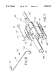
- Pump assembly 46 includes a case 64 which carries electric motor 40, fluid pump 60 and power cells 30. Additionally, pump assembly 46 also includes the plurality of battery terminals or clips 32 which electrically interconnect adjacent power cells 30. Case 64, power cells 30 and clips 32 define a battery pack (not numbered) which is enclosed within housing 20 of lavage instrument 10.
- the plurality of power cells 30 are in the form of a plurality of DC batteries 30, as indicated above.
- Each battery 30 has a positive pole 66 and a negative pole 68 at opposing ends thereof (FIGS. 6 and 7).
- the plurality of batteries 30 are disposed in parallel, side-by-side relationship to each other such that positive poles 66 are disposed adjacent to each other (i.e., all facing the fluid pump 60), and the negative poles 68 are disposed adjacent to each other (i.e., all facing the opposing end of pump assembly 46).
- the plurality of batteries 30 are disposed in a plurality of respective openings 70 (FIGS. 9 and 10) defined by and between case 64 and motor 40. The plurality of batteries 30 thus at least partially surround electric motor 40 carried by case 64.
- Battery terminals or clips 32 provide the dual functionality of both interconnecting power cells 30 in a series arrangement and holding power cells 30 within case 64. More particularly, and as may best be seen in FIGS. 6 and 7, clips 32 connect a positive pole 66 of a particular battery 30 to a negative pole 68 of an adjacent battery 30.
- Each clip 32 is formed from a substantially resilient material and includes opposing ends 72, 74 which extend substantially perpendicular to a longitudinal axis defined by a center portion 76 (FIG. 8). Ends 72, 74 frictionally engage and thereby electrically interconnect the positive pole of one battery 30 to the negative pole of an adjacent battery 30.
- a plurality of projections 78 extending from case 64 hold the respective clips 32 in a relatively stationary position when clips 32 are installed on pump assembly 46.
- pump assembly 46 is enclosed within housing 20 of lavage instrument 10 and provides a self-powered, compact unit to pump fluid from lavage instrument 10.
- strap 21 is removed from the exterior of housing 20 and housing parts 20a, 20b are detached from each other to expose pump assembly 46 disposed therein.
- a user grasps pump assembly 46 and removes it as an entire unit from lavage instrument 10.
- Clips 32 are pulled in a sideways direction (i.e., substantially perpendicular to the longitudinal axis of center portions 76) to remove them from pump assembly 46.
- Batteries 30 may then be slid in an axial direction from the respective openings 70 defined by case 64 to be reused or properly discarded.
Landscapes
- Health & Medical Sciences (AREA)
- Public Health (AREA)
- Veterinary Medicine (AREA)
- General Health & Medical Sciences (AREA)
- Animal Behavior & Ethology (AREA)
- Life Sciences & Earth Sciences (AREA)
- Heart & Thoracic Surgery (AREA)
- Engineering & Computer Science (AREA)
- Chemical Kinetics & Catalysis (AREA)
- Hematology (AREA)
- Anesthesiology (AREA)
- Chemical & Material Sciences (AREA)
- General Chemical & Material Sciences (AREA)
- Electrochemistry (AREA)
- Biomedical Technology (AREA)
- Epidemiology (AREA)
- Pain & Pain Management (AREA)
- Physical Education & Sports Medicine (AREA)
- Rehabilitation Therapy (AREA)
- Pulmonology (AREA)
- Vascular Medicine (AREA)
- Infusion, Injection, And Reservoir Apparatuses (AREA)
- Battery Mounting, Suspending (AREA)
Priority Applications (3)
| Application Number | Priority Date | Filing Date | Title |
|---|---|---|---|
| US08/704,482 US5882319A (en) | 1996-02-15 | 1996-08-21 | Lavage instrument |
| GB9703132A GB2310144A (en) | 1996-02-15 | 1997-02-14 | Lavage instrument |
| CA002197636A CA2197636A1 (fr) | 1996-02-15 | 1997-02-14 | Appareil de lavage |
Applications Claiming Priority (2)
| Application Number | Priority Date | Filing Date | Title |
|---|---|---|---|
| US60223196A | 1996-02-15 | 1996-02-15 | |
| US08/704,482 US5882319A (en) | 1996-02-15 | 1996-08-21 | Lavage instrument |
Related Parent Applications (1)
| Application Number | Title | Priority Date | Filing Date |
|---|---|---|---|
| US60223196A Continuation-In-Part | 1996-02-15 | 1996-02-15 |
Publications (1)
| Publication Number | Publication Date |
|---|---|
| US5882319A true US5882319A (en) | 1999-03-16 |
Family
ID=24410515
Family Applications (1)
| Application Number | Title | Priority Date | Filing Date |
|---|---|---|---|
| US08/704,482 Expired - Lifetime US5882319A (en) | 1996-02-15 | 1996-08-21 | Lavage instrument |
Country Status (3)
| Country | Link |
|---|---|
| US (1) | US5882319A (fr) |
| CA (1) | CA2197635A1 (fr) |
| GB (1) | GB2310143A (fr) |
Cited By (8)
| Publication number | Priority date | Publication date | Assignee | Title |
|---|---|---|---|---|
| US20070044621A1 (en) * | 2005-08-26 | 2007-03-01 | Rote Scott J | Top mounted operator interface for a food slicer |
| US20070044627A1 (en) * | 2005-08-26 | 2007-03-01 | Clem Todd L | Speed and stroke control method and apparatus for a product table of a food slicer |
| US20170056142A1 (en) * | 2014-05-16 | 2017-03-02 | Koninklijke Philips N.V. | Oral cleaning device with adjustable fluid dynamics |
| WO2019092109A1 (fr) * | 2017-11-10 | 2019-05-16 | UTK Solutions GmbH | Système de lavage |
| US20210221211A1 (en) * | 2019-12-30 | 2021-07-22 | Afreecar Llc | Configurable electric vehicle power and propulsion kit |
| US11077236B2 (en) | 2014-12-15 | 2021-08-03 | Genicon, Inc. | Powered lavage handle and associated use therefore |
| US11284572B2 (en) | 2014-12-05 | 2022-03-29 | Pivot Pup Irrigation, LLC | Irrigating soils and crops |
| WO2024012447A1 (fr) * | 2022-07-14 | 2024-01-18 | 格力博(江苏)股份有限公司 | Machine de nettoyage |
Families Citing this family (1)
| Publication number | Priority date | Publication date | Assignee | Title |
|---|---|---|---|---|
| GB9622594D0 (en) * | 1996-10-30 | 1997-01-08 | Bridge House Lab Ltd | Improvements relating to cleansing apparatus and methods |
Citations (26)
| Publication number | Priority date | Publication date | Assignee | Title |
|---|---|---|---|---|
| US615019A (en) * | 1898-11-29 | Motion-converting device for windmills | ||
| US724338A (en) * | 1902-10-02 | 1903-03-31 | Frank Sedivy | Power-transmitting mechanism. |
| US1005690A (en) * | 1910-10-24 | 1911-10-10 | Frank E Carlson | Automobile tire-pump. |
| US1122376A (en) * | 1914-03-26 | 1914-12-29 | Albert M Farmer | Pump. |
| US1232202A (en) * | 1916-03-18 | 1917-07-03 | Emmett J Brown | Air-compressor. |
| US1723100A (en) * | 1921-10-07 | 1929-08-06 | Voorhees Gardner Tufts | Piston apparatus |
| US1734649A (en) * | 1927-12-14 | 1929-11-05 | Tunis Smith | Long-stroke pumping mechanism |
| US2193394A (en) * | 1939-03-22 | 1940-03-12 | Jr Jacob Deckert | Gear shaft pump assembly |
| US2245457A (en) * | 1940-06-29 | 1941-06-10 | Brassell Bryan | Pumping mechanism |
| US2296164A (en) * | 1940-10-04 | 1942-09-15 | Dee E Humphrey | Pump rod actuator |
| US2389918A (en) * | 1939-07-21 | 1945-11-27 | Barr & Stroud Ltd | Reciprocating pump |
| US2470888A (en) * | 1944-10-28 | 1949-05-24 | Henry M Unsehuld | Deep well pump |
| US2705592A (en) * | 1951-02-28 | 1955-04-05 | Albert L Reiser | Fluid displacing mechanism |
| US3227158A (en) * | 1961-05-08 | 1966-01-04 | Aquatec Corp | Method and apparatus for oral hygiene |
| US3299720A (en) * | 1964-07-20 | 1967-01-24 | Mid Continent Steel Casting Co | Piston pump with transverse thread actuator |
| US3696809A (en) * | 1968-08-16 | 1972-10-10 | Inst Rech Diffusion Ind | Method and apparatus for oral hygiene |
| US3811432A (en) * | 1969-12-24 | 1974-05-21 | M Moret | Device for operating a pump so as to produce therefrom a pulsating jet of liquid |
| US4145166A (en) * | 1976-12-06 | 1979-03-20 | Camact Pump Corp. | Displacement pump |
| EP0029636A1 (fr) * | 1979-11-23 | 1981-06-03 | Teledyne Industries, Inc. | Procédé et appareil produisant un jet liquide |
| US4282867A (en) * | 1979-12-05 | 1981-08-11 | Christopher Edward | Cleaning fluid injection device |
| US4315741A (en) * | 1979-01-12 | 1982-02-16 | Bosch-Siemens Hausgerate Gmbh | Hand-operated instrument for dental care or tooth treatment |
| US4655197A (en) * | 1982-12-01 | 1987-04-07 | Snyder Laboratories, Inc. | Lavage system with variable frequency, flow rate and pressure |
| GB2262890A (en) * | 1992-01-03 | 1993-07-07 | Bridge House Lab Limited | Periodontal irrigation equipment |
| US5246367A (en) * | 1989-06-23 | 1993-09-21 | Ricoh Elemex Corporation | Mouth cavity sanitary device |
| US5470305A (en) * | 1993-04-19 | 1995-11-28 | Stryker Corporation | Irrigation handpiece with built in pulsing pump |
| US5542909A (en) * | 1992-06-12 | 1996-08-06 | Camp; Gregory T. | Water jet appliance |
-
1996
- 1996-08-21 US US08/704,482 patent/US5882319A/en not_active Expired - Lifetime
-
1997
- 1997-02-14 CA CA002197635A patent/CA2197635A1/fr not_active Abandoned
- 1997-02-14 GB GB9703065A patent/GB2310143A/en not_active Withdrawn
Patent Citations (26)
| Publication number | Priority date | Publication date | Assignee | Title |
|---|---|---|---|---|
| US615019A (en) * | 1898-11-29 | Motion-converting device for windmills | ||
| US724338A (en) * | 1902-10-02 | 1903-03-31 | Frank Sedivy | Power-transmitting mechanism. |
| US1005690A (en) * | 1910-10-24 | 1911-10-10 | Frank E Carlson | Automobile tire-pump. |
| US1122376A (en) * | 1914-03-26 | 1914-12-29 | Albert M Farmer | Pump. |
| US1232202A (en) * | 1916-03-18 | 1917-07-03 | Emmett J Brown | Air-compressor. |
| US1723100A (en) * | 1921-10-07 | 1929-08-06 | Voorhees Gardner Tufts | Piston apparatus |
| US1734649A (en) * | 1927-12-14 | 1929-11-05 | Tunis Smith | Long-stroke pumping mechanism |
| US2193394A (en) * | 1939-03-22 | 1940-03-12 | Jr Jacob Deckert | Gear shaft pump assembly |
| US2389918A (en) * | 1939-07-21 | 1945-11-27 | Barr & Stroud Ltd | Reciprocating pump |
| US2245457A (en) * | 1940-06-29 | 1941-06-10 | Brassell Bryan | Pumping mechanism |
| US2296164A (en) * | 1940-10-04 | 1942-09-15 | Dee E Humphrey | Pump rod actuator |
| US2470888A (en) * | 1944-10-28 | 1949-05-24 | Henry M Unsehuld | Deep well pump |
| US2705592A (en) * | 1951-02-28 | 1955-04-05 | Albert L Reiser | Fluid displacing mechanism |
| US3227158A (en) * | 1961-05-08 | 1966-01-04 | Aquatec Corp | Method and apparatus for oral hygiene |
| US3299720A (en) * | 1964-07-20 | 1967-01-24 | Mid Continent Steel Casting Co | Piston pump with transverse thread actuator |
| US3696809A (en) * | 1968-08-16 | 1972-10-10 | Inst Rech Diffusion Ind | Method and apparatus for oral hygiene |
| US3811432A (en) * | 1969-12-24 | 1974-05-21 | M Moret | Device for operating a pump so as to produce therefrom a pulsating jet of liquid |
| US4145166A (en) * | 1976-12-06 | 1979-03-20 | Camact Pump Corp. | Displacement pump |
| US4315741A (en) * | 1979-01-12 | 1982-02-16 | Bosch-Siemens Hausgerate Gmbh | Hand-operated instrument for dental care or tooth treatment |
| EP0029636A1 (fr) * | 1979-11-23 | 1981-06-03 | Teledyne Industries, Inc. | Procédé et appareil produisant un jet liquide |
| US4282867A (en) * | 1979-12-05 | 1981-08-11 | Christopher Edward | Cleaning fluid injection device |
| US4655197A (en) * | 1982-12-01 | 1987-04-07 | Snyder Laboratories, Inc. | Lavage system with variable frequency, flow rate and pressure |
| US5246367A (en) * | 1989-06-23 | 1993-09-21 | Ricoh Elemex Corporation | Mouth cavity sanitary device |
| GB2262890A (en) * | 1992-01-03 | 1993-07-07 | Bridge House Lab Limited | Periodontal irrigation equipment |
| US5542909A (en) * | 1992-06-12 | 1996-08-06 | Camp; Gregory T. | Water jet appliance |
| US5470305A (en) * | 1993-04-19 | 1995-11-28 | Stryker Corporation | Irrigation handpiece with built in pulsing pump |
Cited By (10)
| Publication number | Priority date | Publication date | Assignee | Title |
|---|---|---|---|---|
| US20070044621A1 (en) * | 2005-08-26 | 2007-03-01 | Rote Scott J | Top mounted operator interface for a food slicer |
| US20070044627A1 (en) * | 2005-08-26 | 2007-03-01 | Clem Todd L | Speed and stroke control method and apparatus for a product table of a food slicer |
| US20170056142A1 (en) * | 2014-05-16 | 2017-03-02 | Koninklijke Philips N.V. | Oral cleaning device with adjustable fluid dynamics |
| US10130452B2 (en) * | 2014-05-16 | 2018-11-20 | Koninklijke Philips N.V. | Oral cleaning device with adjustable fluid dynamics |
| US11284572B2 (en) | 2014-12-05 | 2022-03-29 | Pivot Pup Irrigation, LLC | Irrigating soils and crops |
| US11077236B2 (en) | 2014-12-15 | 2021-08-03 | Genicon, Inc. | Powered lavage handle and associated use therefore |
| WO2019092109A1 (fr) * | 2017-11-10 | 2019-05-16 | UTK Solutions GmbH | Système de lavage |
| US11446427B2 (en) * | 2017-11-10 | 2022-09-20 | UTK Solution GmbH | Irrigation system |
| US20210221211A1 (en) * | 2019-12-30 | 2021-07-22 | Afreecar Llc | Configurable electric vehicle power and propulsion kit |
| WO2024012447A1 (fr) * | 2022-07-14 | 2024-01-18 | 格力博(江苏)股份有限公司 | Machine de nettoyage |
Also Published As
| Publication number | Publication date |
|---|---|
| CA2197635A1 (fr) | 1997-08-16 |
| GB9703065D0 (en) | 1997-04-02 |
| GB2310143A (en) | 1997-08-20 |
Similar Documents
| Publication | Publication Date | Title |
|---|---|---|
| US4661060A (en) | Dental handpiece | |
| US5882319A (en) | Lavage instrument | |
| US4229634A (en) | Insulated switch arrangement for electric motor | |
| EP2037859B1 (fr) | Dispositif de stimulation sexuelle | |
| RU2367377C1 (ru) | Устройство для ухода за полостью рта | |
| US4726205A (en) | Ignition key with transmitter | |
| WO1990005517A1 (fr) | Appareil de massage electrique | |
| GB9812931D0 (en) | Electric switch | |
| US4596239A (en) | Light source for illuminating and examining devices | |
| US2909316A (en) | Portable fans | |
| ES291075U (es) | Dispositivo puente escobillas para utilizacion en motores electricos de colector | |
| CA2307940A1 (fr) | Lampe de poche actionnee par pression | |
| GB2310144A (en) | Lavage instrument | |
| CN219207075U (zh) | 外科手术器械手柄及外科手术器械 | |
| CN218636133U (zh) | 小型洗牙器和电动牙刷二合一装置 | |
| CN215273516U (zh) | 一种电动牙刷组件 | |
| CN115173543A (zh) | 一种户外电源多级并联结构 | |
| JPS6036251Y2 (ja) | 歯科用コ−ドレスハンドピ−ス治療器 | |
| CN210403787U (zh) | 一种多功能电池包及使用该电池包的工具组件 | |
| JP2801553B2 (ja) | 電動バイブレータ | |
| CN221003039U (zh) | 气泵装置及充气桨板 | |
| CN215025260U (zh) | 颈部按摩仪 | |
| CN214231610U (zh) | 一种电动牙刷 | |
| JPH0115374Y2 (fr) | ||
| CN217828365U (zh) | 一种面部护理仪 |
Legal Events
| Date | Code | Title | Description |
|---|---|---|---|
| AS | Assignment |
Owner name: BRISTOL-MEYERS SQUIBB COMPANY, NEW YORK Free format text: ASSIGNMENT OF ASSIGNORS INTEREST;ASSIGNORS:LACO, MICHAEL J.;RUFENER, MARK R.;REEL/FRAME:008176/0359 Effective date: 19960722 Owner name: BRISTOL-MYERS SQUIBB COMPANY, NEW YORK Free format text: ASSIGNMENT OF ASSIGNORS INTEREST;ASSIGNOR:OLSON, DANIEL H.;REEL/FRAME:008176/0301 Effective date: 19960801 |
|
| STCF | Information on status: patent grant |
Free format text: PATENTED CASE |
|
| FEPP | Fee payment procedure |
Free format text: PAYOR NUMBER ASSIGNED (ORIGINAL EVENT CODE: ASPN); ENTITY STATUS OF PATENT OWNER: LARGE ENTITY |
|
| AS | Assignment |
Owner name: ZIMMER, INC., INDIANA Free format text: ASSIGNMENT OF ASSIGNORS INTEREST;ASSIGNOR:BRISTOL-MYERS SQUIBB COMPANY;REEL/FRAME:012729/0494 Effective date: 20020114 |
|
| FPAY | Fee payment |
Year of fee payment: 4 |
|
| REMI | Maintenance fee reminder mailed | ||
| AS | Assignment |
Owner name: ZIMMER ORTHOPAEDIC SURGICAL PRODUCTS, INC., OHIO Free format text: ASSIGNMENT OF ASSIGNORS INTEREST;ASSIGNOR:ZIMMER, INC.;REEL/FRAME:013845/0422 Effective date: 20020628 |
|
| FPAY | Fee payment |
Year of fee payment: 8 |
|
| FPAY | Fee payment |
Year of fee payment: 12 |