US5890565A - Elevator emergency escape device - Google Patents
Elevator emergency escape device Download PDFInfo
- Publication number
- US5890565A US5890565A US08/688,343 US68834396A US5890565A US 5890565 A US5890565 A US 5890565A US 68834396 A US68834396 A US 68834396A US 5890565 A US5890565 A US 5890565A
- Authority
- US
- United States
- Prior art keywords
- rod
- action
- wheel
- assembly
- cable
- Prior art date
- Legal status (The legal status is an assumption and is not a legal conclusion. Google has not performed a legal analysis and makes no representation as to the accuracy of the status listed.)
- Expired - Fee Related
Links
- 230000005540 biological transmission Effects 0.000 claims abstract description 44
- 230000033001 locomotion Effects 0.000 claims description 9
- 238000006073 displacement reaction Methods 0.000 claims description 4
- 239000012530 fluid Substances 0.000 claims 2
- 230000001276 controlling effect Effects 0.000 description 1
- 230000001105 regulatory effect Effects 0.000 description 1
- 230000000630 rising effect Effects 0.000 description 1
Images


Classifications
-
- B—PERFORMING OPERATIONS; TRANSPORTING
- B66—HOISTING; LIFTING; HAULING
- B66D—CAPSTANS; WINCHES; TACKLES, e.g. PULLEY BLOCKS; HOISTS
- B66D5/00—Braking or detent devices characterised by application to lifting or hoisting gear, e.g. for controlling the lowering of loads
- B66D5/02—Crane, lift hoist, or winch brakes operating on drums, barrels, or ropes
- B66D5/24—Operating devices
-
- B—PERFORMING OPERATIONS; TRANSPORTING
- B66—HOISTING; LIFTING; HAULING
- B66B—ELEVATORS; ESCALATORS OR MOVING WALKWAYS
- B66B5/00—Applications of checking, fault-correcting, or safety devices in elevators
- B66B5/02—Applications of checking, fault-correcting, or safety devices in elevators responsive to abnormal operating conditions
- B66B5/027—Applications of checking, fault-correcting, or safety devices in elevators responsive to abnormal operating conditions to permit passengers to leave an elevator car in case of failure, e.g. moving the car to a reference floor or unlocking the door
Definitions
- the present invention relates generally to an elevator, and more particular to an emergency escape device of the elevator.
- the normal operation of an elevator is vulnerable to interruption caused by various factors such as a mechanical failure, a power outage, a fire in the building in which the elevator is located, and so forth.
- the elevator passengers are therefore equally vulnerable to being trapped in the elevator.
- the situation can become worse if the elevator is disabled midway between two floors.
- the existing elevators are generally not equipped with a emergency escape device enabling the trapped passengers to operate the disabled elevator to safety.
- the device comprises a brake which is mounted on the transmission shaft of a motor located in the mechanical control room of an elevator. Mounted coaxially on the motor transmission shaft is an action wheel engageable with a transmission wheel on which an action cable is wound.
- An action rod is provided with a force applying device which comprises a force output member extending to reach the elevator cab such that the action rod is controlled by the force output member so as to bring about the release of the braking action, thereby enabling the disabled elevator cab to be moved by the action cable to safety.
- the brake mounted on the motor transmission shaft is of a drum type.
- the force output member is a hydraulic (or air) pressure conveying tube, which has one end that is located in the elevator cab such that it is connected with a control cylinder.
- the pressure conveying tube has another end which is connected with a driven cylinder located in the mechanical control room.
- the control cylinder which is located in the elevator cab, is composed of a piston rod which is provided with an operation handle.
- the piston rod is actuated by the movement of the operation handle so as to regulate the conveying of the hydraulic (or air) pressure to control the action of the piston rod of the driven cylinder.
- the action rod is then actuated directly or indirectly by the action of the piston rod of the driven cylinder so as to bring about the release of the braking action of the brake.
- the force output member may be a force applying cable or chain, which is fastened at one end thereof with a weight located at the bottom of the elevator shaft.
- the force applying cable or chain is fastened at another end thereof with a member which is located in the mechanical control room and is capable of actuating the action rod to bring about the release of the braking action.
- the operation of the device of the present invention is attained by the force output member which is capable of actuating the action rod to bring about the release of the braking action of the brake and is also capable of causing the transmission wheel to engage the action wheel.
- the elevator cab can be moved up and down by an action cable wound on the rotary wheel which is linked with the transmission wheel.
- the transmission wheel which is engageable with the action wheel mounted on the motor shaft, is provided with a speed limiting friction wheel for moderating the lifting or descending speed of the elevator.
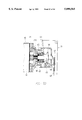
- FIG. 1 shows a schematic view of a first preferred embodiment of the present invention.
- FIG. 2 shows an enlarged view of a portion of the first preferred embodiment of the present invention.
- FIG. 2-1 shows a schematic view of another embodiment of the force application rod as shows in FIG. 2.
- FIG. 3 shows a partial sectional view of a brake of the present invention.
- FIG. 4 shows a schematic view of the control cylinder of the elevator cab of the present invention.
- FIG. 5 shows a schematic view of the action cable at work according to the first preferred embodiment of the present invention.
- FIG. 6 shows a schematic view of a second preferred embodiment of the present invention.
- FIG. 7 shows a schematic view of a third preferred embodiment of the present invention.
- FIG. 8 shows a schematic view of the internal structures of the speed-limiting friction wheel of the third preferred embodiment of the present invention.
- FIG. 9 shows a schematic view of a fourth preferred embodiment of the present invention.
- FIG. 10 shows a schematic view of the cam acting on the action rod of the fourth preferred embodiment of the present invention.
- FIG. 11 shows a schematic view of the rotary rod on which the transmission wheel and the rotary wheel are mounted.
- FIG. 12 is a schematic view showing that the cam works to open up the brake arm of the present invention.
- FIG. 13 is a schematic view showing that the cam of the fourth preferred embodiment of the present invention is provided with a connection rod for opening up the brake arm.
- FIG. 14 is a schematic view showing that the cam of the fourth preferred embodiment of the present invention is provided with a through hole engageable with the action rod.
- FIG. 15 shows a schematic view of a fifth preferred embodiment of the present invention.
- FIG. 16 is a schematic view showing that the crank of the fifth preferred embodiment of the present invention is at work to open up the brake arm.
- FIG. 17 is a top schematic view of the present invention as shown in FIG. 16.
- FIG. 18 is a sectional view of the fifth preferred embodiment of the present invention.
- FIG. 19 is a schematic view showing that the pull rod of the fifth preferred embodiment of the present invention is at work to actuate the action rod to bring about the release of the braking action.
- FIG. 20 show a top schematic view of a portion of the fifth referred embodiment of the present invention.
- FIG. 21 shows a schematic view of a sixth preferred embodiment of the present invention.
- FIG. 22 shows a schematic view of a seventh preferred embodiment of the present invention.
- FIG. 23 is a schematic view showing the partial internal structure of the seventh preferred embodiment of the present invention.
- FIG. 24 is a schematic view showing that the seventh preferred embodiment of the present invention is provided with a speed-limiting centrifugal brake block.
- an elevator emergency escape device embodied in the present invention is composed of a brake 20 which is mounted on a transmission shaft 11 of a motor 10 located in a mechanical control room 1.
- a brake 20 which is mounted on a transmission shaft 11 of a motor 10 located in a mechanical control room 1.
- an action wheel 30 engageable with a transmission wheel 40 which is linked with a rotary wheel 41.
- An action cable 50 is wound around the rotary wheel 41.
- An action rod 60 is capable of controlling the brake 20 and is provided at one end thereof with a force applying device 70 which is composed of a force output member 71 extending to reach an elevator cab 2.
- the action rod 60 is controlled by the force output member 71 to bring about the release of the braking action of the brake 20, thereby enabling the elevator cab 2 to be moved up and down by the action cable 50 to arrive at a safe floor to allow passengers in the cab 2 to escape.
- the force output member 71 of the first preferred embodiment of the present invention is a hydraulic (or air) pressure conveying tube 710, which is disposed at one end thereof in a predetermined location of the elevator cab 2 in conjunction with a control tube of the elevator cab 2 such that the hydraulic pressure conveying tube 710 is connected with a hydraulic (or air pressure) control cylinder 711, and that the hydraulic pressure conveying tube 710 is fastened at another end thereof with a driven cylinder 712 located in the mechanical control room 1.
- the piston rod of the control cylinder 711 is provided with an operation handle 713 capable of actuating the piston rod to bring about the conveying of the hydraulic pressure by the conveying tube 710.
- the action of the piston rod of the driven cylinder 712 is regulated by the hydraulic pressure conveyed by the conveying tube 710.
- the piston rod of the driven cylinder 712 is fastened with one end of a force applying rod 72 of the force applying device 70.
- the force applying rod 72 is mounted horizontally on the action rod 60.
- the force applying rod 72 is provided radially with a support rod 720, which is in turn provided with an elastic member 721 urging the force applying rod 72 to swing downwards to press the action rod 60 so as to bring about the release of the braking action.
- the transmission wheel 40 and the rotary wheel 41 are located by the force applying rod 72.
- An idle wheel 42 is located by another end of the action cable 50 wound on the rotary wheel 41, so as to enable the transmission wheel 40 to engage the action wheel 30 when the force applying rod 72 is caused to swing downwards to bring about the release of the braking action, as shown in FIG. 5.
- the elevator cab 2 is provided with a window 200 through which the action cable 50 can be reached by a cab passenger. As the action cable 50 is pulled, the shaft 11 of the motor 10 is turned to move the elevator cab 2 to a safe floor to allow the cab passengers to escape.
- the cab passengers have an easy access to the operation handle 713 by breaking or opening the window 200.
- the elevator cab 2 can be moved to a safe floor by pulling manually the action cable 50.
- the force output member 71 of the present invention may be a force applying cable 714, which is fastened at one end thereof with a tension weight 715 located at the bottom of the elevator shaft, and is fastened at another end thereof with the force applying rod 72 located in the mechanical control room 1.
- the force applying cable 714 can be reached through the window 200.
- the force applying rod 72 is actuated to swing downwards to cause the action rod 60 to bring about the release of the braking action of the brake 20.
- the elevator cab 2 can be then moved to a safe floor by pulling the action cable 50 manually.
- the force applying rod 72 is provided with a weight 722 capable of causing the force applying rod 72 to swing back to its original position when the force applying rod 72 is not acted on by the force output member 71.
- an action wheel 30 is mounted on the shaft 11 of the motor 10 of the high-speed elevator such that the action wheel 30 is engaged with a transmission wheel 40 which is provided with a speed-limiting friction wheel 400, as shown in FIG. 8.
- the speed-limiting friction wheel 400 has a centrifugal brake block 401 which is intended for use in decelerating the transmission wheel 40 when the transmission wheel 40 is turning too fast.
- the speed-limiting friction wheel 400 is therefore used to decelerate the shaft 11 of the motor 10 so as to enable the elevator cab to arrive at a safe floor at a slower pace.
- the piston rod of the driven cylinder 712 is fastened at one end thereof with a driving rod 73 which is in turn fastened at another end thereof with a rotary rod 731 located on a bearing support seat 732 and the action rod 60.
- the driving rod 73 is provided with a cam 733 opposite to the action rod 60, as shown in FIG. 10.
- the rotary rod 731 is actuated by the driving rod 73 so as to cause the cam 733 to press the action rod 60, thereby result in the release of the braking action.
- the rotary rod 731 is provided with a wheel seat 734 fastened therewith eccentrically. As shown in FIG.
- the wheel seat 734 is provided with an axle 735 parallel to the rotary rod 731.
- the transmission wheel 40 and the rotary wheel 41 are mounted on the axle 735.
- the action cable 50 is wound on the rotary wheel 41.
- the wheel seat 734 is caused to swing downwards, thereby causing the transmission wheel 40 to engage the action wheel 30 which is mounted on the shaft 11 of the motor 10.
- the elevator cab can be lifted or descended by the action cable 60.
- the cam 733 has two projections, as shown in FIG. 12. The cam 733 can be mounted between two brake arms of the brake 20.
- the cam 733 in motion is capable of pushing the brake arm outwards so as to cause the shaft 11 of the motor to be relieved of the braking action.
- the cam 733 is provided with two eccentric connection rods 736.
- the brake arm is pushed outwards by the eccentric connection rods 736 to bring about the release of the braking action.
- the cam 733 is provided with an eccentric through hole 737 which is engaged with one end of an action rod 61.
- the action rod 61 is actuated by the cam 733 to swing so as to bring about the release of the braking action of the brake 20.
- the piston rod of the driven cylinder 712 (or the force applying cable 714) is fastened with a swing rod 74 which is in turn fastened at another end thereof with a moving rod 741 located by a support seat 742 such that the moving rod 741 is movably located on the action rod 60.
- the moving rod 741 is provided with a slanted projection 743.
- the transmission wheel 40 and the rotary wheel 41 may be mounted on the moving rod 741.
- the action cable 50 is wound on the rotary wheel 41 so as to enable the transmission wheel 40 to displace axially when the moving rod 741 is caused to displace axially to bring about the release of the braking action.
- the transmission wheel 40 is engaged with the action wheel 30 mounted on the shaft 11 of the motor 10.
- the elevator cab can be thus moved up and down by pulling the action cable 50.
- the projection 743 of the moving rod 741 can be located between the two brake arms of the brake 20, as shown in FIG. 16. Located between the two brake arms are two movable cranks 744, as shown in FIGS. 17 and 18. The operation arms of the two cranks 744 are in contact with the projection 743.
- the operation arms of the two cranks 744 are urged by the urging rods of the electromagnetic device such that the cranks 744 are caused to swivel, and that another ends of the cranks 744 push the upper ends of the brake arms of the brake to move outwards so as to enable the shaft 11 of the motor 10 to be relieved of the braking action.
- the moving rod 741 is displaced axially, the two cranks 744 are pushed by the projection 743 to swivel so as to push the brake arms outwards.
- the moving rod 741 is provided with a pull rod 745 fastened therewith such that the pull rod 745 is fastened at another end thereof with an action rod 62.
- the pull rod 745 is activated to actuate the action rod 62 to turn, thereby resulting in the release of the braking action of the brake 20.
- the release of the braking action of the brake 20 can be brought about in various ways by the elevator cab passenger such that the elevator cab is manually operated to arrive at a safe floor where the trapped passengers can escape for safety.
- the shaft 11 of the motor 10 is provided with a disk brake 21 capable of being controlled by an action rod 63 which is provided at one end thereof with the force applying device 70 similar to the one described above.
- the force output member 71 of the force applying device 70 is a hydraulic (or air) pressure conveying tube 710, which has one end located in the elevator cab 2 in conjunction with the control tube of the elevator cab 2 such that the conveying tube 710 is connected with a hydraulic (or air) pressure control cylinder 711.
- the conveying tube 710 has another end which is connected with a driven cylinder 712 located in a mechanical control room 1.
- the piston rod of the control cylinder 711 is provided with an operation handle 713 capable of actuating the piston rod to bring about the transportation of the hydraulic (or air) pressure through the conveying tube 710 to the driven cylinder 712 in which the piston rod is actuated by the pressure.
- the release of the braking action of the disk brake 21 is brought about by the action rod 63 which is fastened with the piston rod of the driven cylinder 712 and is provided with a wheel rod 64 fastened therewith.
- the wheel rod 64 is located by a support seat 640 such that the transmission wheel 40 and the rotary wheel 41 are mounted on the wheel rod 64.
- the action cable 50 is wound on the rotary wheel 41 such that the axial displacement of the wheel rod 64 is brought about by the action rod 63 in motion, and that the transmission wheel 40 is engaged with the action wheel 30.
- the elevator cab 2 can be manually operated to move up and down by means of the action cable 50.
- the manual operation of the elevator cab 2 is brought about by a passenger located in the elevator cab 2.
- the force output member 71 of the force applying device 70 may be a force applying cable or chain in place of the pressure conveying tube 710.
- the force applying cable or chain is fastened with the operation end of the action rod 63 such that the action rod 63 can be actuated by the force applying cable or chain to bring about the release of the braking action of the disk brake 21.
- the control of the braking action of the disk brake 21 is brought about by the swinging motion of the action rod 63.
- the disk brake 21 may be mounted on another end of the shaft 11 of the motor 10 such that the disk brake 21 and the action wheel 30 are located on the same side, with the action wheel 30 being mounted on a shaft sleeve 65 capable of being actuated by the action rod 63.
- a clutch 66 Located between the shaft sleeve 65 and the disk 210 of the disk brake 21 is a clutch 66, which is urged by a spring 67 to remain in the state of becoming engaged with the disk 210.
- the transmission wheel 40 and the rotary wheel 41 are mounted on an axle 68 parallel to the shaft 11 of the motor 10.
- the action cable 50 is wound on the rotary wheel 41 such that the shaft sleeve 65 is actuated by the action rod 63 to displace axially so as to force the disk 210 to move rearwards, thereby causing the shaft 11 to be free from the braking action.
- the axial displacement of the shaft sleeve 65 brings about the engagement of the action wheel 30 with the transmission wheel 40, thereby causing the action cable 50 to driven the shaft 11 of the motor 10 so as to move the elevator cab 2 up and down.
- the shaft sleeve 65 must be provided with a speed limiting centrifugal brake block 650.
- the shaft sleeve 65 When the disk 210 mounted on the shaft 11 of the motor 10 is pushed rearwards by the shaft sleeve 65 to bring about the release of the braking action, the shaft sleeve 65 is actuated by the disk 210 to rotate in view of the inertia rotation of the shaft 11 of the motor 10. Under the normal operating condition, the act of clutching of the disk 210 is controlled by an electromagnetic device. As the clutch 66 is not in the state of being engaged, the shaft sleeve 65 can not be actuated by the disk 210 to rotate. The speed limiting centrifugal brake block 650 kicks in automatically to reduce the rotation speed of the shaft sleeve 65 when the rotation speed of the shaft sleeve 65 exceeds a certain limit.
- the rotation speed of the shaft 11 of the motor 10 is reduced to slow down the moving velocity of the elevator cab.
- the shaft sleeve 65 and the action wheel 30 are linked by a ratchet 651.
- the action wheel 30 is directly engaged with the transmission wheel 40 which is driven by the rotary wheel 41 which is actuated by the pulling action of the action cable 50.
- the release of the braking action is attained by the axial displacement of the shaft sleeve 65.
Landscapes
- Engineering & Computer Science (AREA)
- Mechanical Engineering (AREA)
- Maintenance And Inspection Apparatuses For Elevators (AREA)
Priority Applications (3)
| Application Number | Priority Date | Filing Date | Title |
|---|---|---|---|
| EP96112016A EP0820954A1 (en) | 1996-07-25 | 1996-07-25 | Elevator emergency escape device |
| US08/688,343 US5890565A (en) | 1996-07-25 | 1996-07-30 | Elevator emergency escape device |
| JP8231348A JPH1077169A (ja) | 1996-07-25 | 1996-08-13 | エレベータにおける緊急避難装置 |
Applications Claiming Priority (3)
| Application Number | Priority Date | Filing Date | Title |
|---|---|---|---|
| EP96112016A EP0820954A1 (en) | 1996-07-25 | 1996-07-25 | Elevator emergency escape device |
| US08/688,343 US5890565A (en) | 1996-07-25 | 1996-07-30 | Elevator emergency escape device |
| JP8231348A JPH1077169A (ja) | 1996-07-25 | 1996-08-13 | エレベータにおける緊急避難装置 |
Publications (1)
| Publication Number | Publication Date |
|---|---|
| US5890565A true US5890565A (en) | 1999-04-06 |
Family
ID=27237375
Family Applications (1)
| Application Number | Title | Priority Date | Filing Date |
|---|---|---|---|
| US08/688,343 Expired - Fee Related US5890565A (en) | 1996-07-25 | 1996-07-30 | Elevator emergency escape device |
Country Status (3)
| Country | Link |
|---|---|
| US (1) | US5890565A (ja) |
| EP (1) | EP0820954A1 (ja) |
| JP (1) | JPH1077169A (ja) |
Cited By (21)
| Publication number | Priority date | Publication date | Assignee | Title |
|---|---|---|---|---|
| US6116380A (en) * | 1998-12-08 | 2000-09-12 | Wang; Chiu Nan | Elevator provided with emergency escape |
| US6179090B1 (en) * | 1996-11-21 | 2001-01-30 | Alan V. Casas | Elevator hoist brake release apparatus |
| US6273216B1 (en) * | 1998-09-28 | 2001-08-14 | Inventio Ag | Emergency release device |
| US6464043B2 (en) * | 2001-03-08 | 2002-10-15 | Jiun Jyh Wang | Elevator emergency escape device |
| US6494296B2 (en) * | 2000-04-27 | 2002-12-17 | Inventio Ag | Device for signaling movement of an elevator car during the evacuation of elevator passengers |
| US6516921B1 (en) * | 2001-07-17 | 2003-02-11 | Jiun Jyh Wang | Protective means against inertial slip of elevator cab during brake release in an emergency |
| US6598709B2 (en) * | 2000-03-31 | 2003-07-29 | Inventio Ag | Auxiliary device for displacing a payload receptacle of an elevator |
| US20030168287A1 (en) * | 2000-07-29 | 2003-09-11 | Theodor Helmle | Elevator car with a driving pulley driving machine integrated therein |
| US20040026179A1 (en) * | 2000-08-07 | 2004-02-12 | Eros Assirelli | Cable lift with in shaft machinery |
| US20040195047A1 (en) * | 2003-04-07 | 2004-10-07 | Wang Chiu Nan | Elevator |
| US20050051388A1 (en) * | 2003-09-09 | 2005-03-10 | Wang Jiun Jyh | Backup power device for elevator |
| USRE38835E1 (en) * | 1997-05-28 | 2005-10-18 | Otis Elevator Company | Remote brake release mechanism for an elevator machine |
| US20070246694A1 (en) * | 2004-08-27 | 2007-10-25 | Hyun-Dal Lee | Life Saving Implement |
| US20080078625A1 (en) * | 2006-08-14 | 2008-04-03 | Chiu Nan Wang | Emergency escape apparatus for elevator |
| US20080078627A1 (en) * | 2006-08-31 | 2008-04-03 | Chiu Nan Wang | Elevator escape arrangement |
| US20090020371A1 (en) * | 2007-07-20 | 2009-01-22 | Chiu Nan Wang | Elevator evacuation apparatus |
| FR3000774A1 (fr) * | 2013-01-08 | 2014-07-11 | Eiffage Construction Metallique | Systeme de commande et de limitation de vitesse pour controler le mouvement d'un organe mobile |
| US20150122590A1 (en) * | 2013-11-04 | 2015-05-07 | Kone Corporation | Brake assembly for an elevator |
| US20160376126A1 (en) * | 2015-06-25 | 2016-12-29 | Trust <T> Lift Corp. | Emergency movement device for an elevator or lift |
| CN106395561A (zh) * | 2016-12-08 | 2017-02-15 | 宁波永良电梯技术发展有限公司 | 螺杆电梯及其控制方法 |
| US20250304413A1 (en) * | 2024-04-02 | 2025-10-02 | Thomson Industries, Inc. | System for Controlled Descent of a Lift |
Families Citing this family (5)
| Publication number | Priority date | Publication date | Assignee | Title |
|---|---|---|---|---|
| EP1024104A1 (en) * | 1999-01-27 | 2000-08-02 | Chiu Nan Wang | Auxiliary emergency escape device of elevator |
| EP1412183A1 (de) | 2001-08-03 | 2004-04-28 | Koenig & Bauer Aktiengesellschaft | Druckwerke einer druckmaschine |
| KR100713656B1 (ko) * | 2001-10-29 | 2007-05-02 | 첸 융-히신 | 엘리베이터의 보조구명장치 |
| CN106429735B (zh) * | 2016-10-25 | 2018-07-10 | 中国建筑科学研究院建筑机械化研究分院 | 手动离合增力矩装置 |
| CN107572336B (zh) * | 2017-10-18 | 2023-03-03 | 杭州道勒斯科技有限公司 | 电梯启闭牵引一体式应急操控设备 |
Citations (4)
| Publication number | Priority date | Publication date | Assignee | Title |
|---|---|---|---|---|
| US2265891A (en) * | 1941-01-14 | 1941-12-09 | Otis Elevator Co | Operating mechanism for elevators |
| US4592450A (en) * | 1982-08-06 | 1986-06-03 | Wolfgang Schaffer | Elevator |
| US5680911A (en) * | 1996-03-05 | 1997-10-28 | Wang; Chiou Nan | Elector emergency device |
| US5713433A (en) * | 1995-09-21 | 1998-02-03 | Wang Chiou N | Auxiliary escape of elevator |
Family Cites Families (3)
| Publication number | Priority date | Publication date | Assignee | Title |
|---|---|---|---|---|
| US2941625A (en) * | 1955-07-07 | 1960-06-21 | Souza Arthur Jadir De Andrade | Machine for maneuvering elevators |
| DE3419443A1 (de) * | 1984-05-24 | 1985-11-28 | Schaltgerätebau Walter Nunn, 8130 Starnberg | Vorrichtung zum anheben oder absenken einer aufzugskabine aus einer lage, in der sie durch ausfall ihres normalantriebs stehengeblieben ist und unter der wirkung einer sie in ihrer lage festhaltenden festhaltevorrichtung steht |
| DE29515588U1 (de) * | 1995-09-29 | 1995-11-30 | Wang, Chiou Nan, Fengyuan, Taichung | Hilfsfluchtweg für einen Aufzug |
-
1996
- 1996-07-25 EP EP96112016A patent/EP0820954A1/en not_active Withdrawn
- 1996-07-30 US US08/688,343 patent/US5890565A/en not_active Expired - Fee Related
- 1996-08-13 JP JP8231348A patent/JPH1077169A/ja active Pending
Patent Citations (4)
| Publication number | Priority date | Publication date | Assignee | Title |
|---|---|---|---|---|
| US2265891A (en) * | 1941-01-14 | 1941-12-09 | Otis Elevator Co | Operating mechanism for elevators |
| US4592450A (en) * | 1982-08-06 | 1986-06-03 | Wolfgang Schaffer | Elevator |
| US5713433A (en) * | 1995-09-21 | 1998-02-03 | Wang Chiou N | Auxiliary escape of elevator |
| US5680911A (en) * | 1996-03-05 | 1997-10-28 | Wang; Chiou Nan | Elector emergency device |
Cited By (32)
| Publication number | Priority date | Publication date | Assignee | Title |
|---|---|---|---|---|
| US6179090B1 (en) * | 1996-11-21 | 2001-01-30 | Alan V. Casas | Elevator hoist brake release apparatus |
| USRE38835E1 (en) * | 1997-05-28 | 2005-10-18 | Otis Elevator Company | Remote brake release mechanism for an elevator machine |
| US6273216B1 (en) * | 1998-09-28 | 2001-08-14 | Inventio Ag | Emergency release device |
| US6116380A (en) * | 1998-12-08 | 2000-09-12 | Wang; Chiu Nan | Elevator provided with emergency escape |
| US6598709B2 (en) * | 2000-03-31 | 2003-07-29 | Inventio Ag | Auxiliary device for displacing a payload receptacle of an elevator |
| US6494296B2 (en) * | 2000-04-27 | 2002-12-17 | Inventio Ag | Device for signaling movement of an elevator car during the evacuation of elevator passengers |
| US20030168287A1 (en) * | 2000-07-29 | 2003-09-11 | Theodor Helmle | Elevator car with a driving pulley driving machine integrated therein |
| US6892862B2 (en) * | 2000-07-29 | 2005-05-17 | Alpha Getriebebau Gmbh | Elevator car with a driving pulley driving machine integrated therein |
| US20040026179A1 (en) * | 2000-08-07 | 2004-02-12 | Eros Assirelli | Cable lift with in shaft machinery |
| US7108105B2 (en) * | 2000-08-07 | 2006-09-19 | Space Lift S.R.L. | Cable lift without a machine room |
| US6464043B2 (en) * | 2001-03-08 | 2002-10-15 | Jiun Jyh Wang | Elevator emergency escape device |
| US6516921B1 (en) * | 2001-07-17 | 2003-02-11 | Jiun Jyh Wang | Protective means against inertial slip of elevator cab during brake release in an emergency |
| US20040195047A1 (en) * | 2003-04-07 | 2004-10-07 | Wang Chiu Nan | Elevator |
| US7503433B2 (en) * | 2003-04-07 | 2009-03-17 | Chiu Nan Wang | Elevator |
| US20050051388A1 (en) * | 2003-09-09 | 2005-03-10 | Wang Jiun Jyh | Backup power device for elevator |
| US6966409B2 (en) * | 2003-09-09 | 2005-11-22 | Jiun Jyh Wang | Backup power device for elevator |
| US20070246694A1 (en) * | 2004-08-27 | 2007-10-25 | Hyun-Dal Lee | Life Saving Implement |
| US8181741B2 (en) * | 2004-08-27 | 2012-05-22 | Implement Saving Precious Life Co., Ltd. | Life saving implement |
| US20080078625A1 (en) * | 2006-08-14 | 2008-04-03 | Chiu Nan Wang | Emergency escape apparatus for elevator |
| US7392885B2 (en) * | 2006-08-14 | 2008-07-01 | Chiu Nan Wang | Emergency escape apparatus for elevator |
| US7556126B2 (en) * | 2006-08-31 | 2009-07-07 | Chiu Nan Wang | Elevator escape arrangement |
| US20080078627A1 (en) * | 2006-08-31 | 2008-04-03 | Chiu Nan Wang | Elevator escape arrangement |
| US20090020371A1 (en) * | 2007-07-20 | 2009-01-22 | Chiu Nan Wang | Elevator evacuation apparatus |
| US7607515B2 (en) * | 2007-07-20 | 2009-10-27 | Chiu Nan Wang | Elevator evacuation apparatus |
| EP2762434A1 (fr) * | 2013-01-08 | 2014-08-06 | EIFFAGE Construction Métallique | Système de commande et de limitation de vitesse pour contrôler le mouvement d'un organe mobile |
| FR3000774A1 (fr) * | 2013-01-08 | 2014-07-11 | Eiffage Construction Metallique | Systeme de commande et de limitation de vitesse pour controler le mouvement d'un organe mobile |
| US20150122590A1 (en) * | 2013-11-04 | 2015-05-07 | Kone Corporation | Brake assembly for an elevator |
| US9764926B2 (en) * | 2013-11-04 | 2017-09-19 | Kone Corporation | Brake assembly for an elevator |
| US20160376126A1 (en) * | 2015-06-25 | 2016-12-29 | Trust <T> Lift Corp. | Emergency movement device for an elevator or lift |
| US9815666B2 (en) * | 2015-06-25 | 2017-11-14 | Trust <T> Lift Corp. | Emergency movement device for an elevator or lift |
| CN106395561A (zh) * | 2016-12-08 | 2017-02-15 | 宁波永良电梯技术发展有限公司 | 螺杆电梯及其控制方法 |
| US20250304413A1 (en) * | 2024-04-02 | 2025-10-02 | Thomson Industries, Inc. | System for Controlled Descent of a Lift |
Also Published As
| Publication number | Publication date |
|---|---|
| EP0820954A1 (en) | 1998-01-28 |
| JPH1077169A (ja) | 1998-03-24 |
Similar Documents
| Publication | Publication Date | Title |
|---|---|---|
| US5890565A (en) | Elevator emergency escape device | |
| EP2112115B1 (en) | Elevator car brake with shoes actuated by springs coupled to gear drive assembly | |
| US8256579B2 (en) | Elevator car brake | |
| US5310022A (en) | Mechanical overspeed safety device | |
| USRE38835E1 (en) | Remote brake release mechanism for an elevator machine | |
| JPS60209498A (ja) | ウオーム安全装置を有するホイスト | |
| CN1121974C (zh) | 牵引轮式电梯的制动方法及牵引轮式电梯 | |
| US6516921B1 (en) | Protective means against inertial slip of elevator cab during brake release in an emergency | |
| JP2000211841A (ja) | エレベ―タ装置の動きを停止させる装置 | |
| CN1972856A (zh) | 一种用于升降被困电梯的应急装置 | |
| CN101172553A (zh) | 一种电梯的无绳限速系统 | |
| CN113291947A (zh) | 电梯限速器 | |
| KR100301643B1 (ko) | 승강기비상탈출조립체 | |
| CN1305748C (zh) | 电梯用紧急制动装置 | |
| US20030015377A1 (en) | Double brake protection device for elevator | |
| CN110436296A (zh) | 一种曳引电梯紧急制动用限速器 | |
| JPH07242377A (ja) | エレベーター装置 | |
| CN114408695B (zh) | 一种施工升降机用手动匀速下降限速机构 | |
| CN217102582U (zh) | 电梯限速器 | |
| KR100388156B1 (ko) | 엘리베이터용 로프 제동장치 | |
| JP4316995B2 (ja) | 乗客コンベア及びその制動方法 | |
| CN212403069U (zh) | 轿厢的驻车装置 | |
| CN1141243C (zh) | 电梯解除刹车脱困防止惯性滑移的多重保护装置 | |
| JPH08333058A (ja) | エレベータ装置 | |
| CN115744638B (zh) | 一种机械式超速保护装置 |
Legal Events
| Date | Code | Title | Description |
|---|---|---|---|
| REMI | Maintenance fee reminder mailed | ||
| LAPS | Lapse for failure to pay maintenance fees | ||
| LAPS | Lapse for failure to pay maintenance fees |
Free format text: PATENT EXPIRED FOR FAILURE TO PAY MAINTENANCE FEES (ORIGINAL EVENT CODE: EXP.); ENTITY STATUS OF PATENT OWNER: SMALL ENTITY |
|
| STCH | Information on status: patent discontinuation |
Free format text: PATENT EXPIRED DUE TO NONPAYMENT OF MAINTENANCE FEES UNDER 37 CFR 1.362 |
|
| FP | Lapsed due to failure to pay maintenance fee |
Effective date: 20030406 |