US5890568A - Continuously variable twin-tube shock damper - Google Patents
Continuously variable twin-tube shock damper Download PDFInfo
- Publication number
- US5890568A US5890568A US08/849,783 US84978397A US5890568A US 5890568 A US5890568 A US 5890568A US 84978397 A US84978397 A US 84978397A US 5890568 A US5890568 A US 5890568A
- Authority
- US
- United States
- Prior art keywords
- valve
- piston
- control valve
- damping
- hollow
- Prior art date
- Legal status (The legal status is an assumption and is not a legal conclusion. Google has not performed a legal analysis and makes no representation as to the accuracy of the status listed.)
- Expired - Lifetime
Links
Images


Classifications
-
- F—MECHANICAL ENGINEERING; LIGHTING; HEATING; WEAPONS; BLASTING
- F16—ENGINEERING ELEMENTS AND UNITS; GENERAL MEASURES FOR PRODUCING AND MAINTAINING EFFECTIVE FUNCTIONING OF MACHINES OR INSTALLATIONS; THERMAL INSULATION IN GENERAL
- F16F—SPRINGS; SHOCK-ABSORBERS; MEANS FOR DAMPING VIBRATION
- F16F9/00—Springs, vibration-dampers, shock-absorbers, or similarly-constructed movement-dampers using a fluid or the equivalent as damping medium
- F16F9/32—Details
- F16F9/44—Means on or in the damper for manual or non-automatic adjustment; such means combined with temperature correction
- F16F9/46—Means on or in the damper for manual or non-automatic adjustment; such means combined with temperature correction allowing control from a distance, i.e. location of means for control input being remote from site of valves, e.g. on damper external wall
- F16F9/465—Means on or in the damper for manual or non-automatic adjustment; such means combined with temperature correction allowing control from a distance, i.e. location of means for control input being remote from site of valves, e.g. on damper external wall using servo control, the servo pressure being created by the flow of damping fluid, e.g. controlling pressure in a chamber downstream of a pilot passage
-
- F—MECHANICAL ENGINEERING; LIGHTING; HEATING; WEAPONS; BLASTING
- F16—ENGINEERING ELEMENTS AND UNITS; GENERAL MEASURES FOR PRODUCING AND MAINTAINING EFFECTIVE FUNCTIONING OF MACHINES OR INSTALLATIONS; THERMAL INSULATION IN GENERAL
- F16F—SPRINGS; SHOCK-ABSORBERS; MEANS FOR DAMPING VIBRATION
- F16F9/00—Springs, vibration-dampers, shock-absorbers, or similarly-constructed movement-dampers using a fluid or the equivalent as damping medium
- F16F9/32—Details
- F16F9/50—Special means providing automatic damping adjustment, i.e. self-adjustment of damping by particular sliding movements of a valve element, other than flexions or displacement of valve discs; Special means providing self-adjustment of spring characteristics
- F16F9/512—Means responsive to load action, i.e. static load on the damper or dynamic fluid pressure changes in the damper, e.g. due to changes in velocity
Definitions
- the invention relates to a continuously variable twin-tube shock damper comprising:
- a piston which is movable in the working cylinder and has a passage and a non-return valve which permits only an upward flow through the said passage with negligible damping capacity
- a disc which has one or more passages and is arranged inside the working cylinder between the piston and the baseplate,
- a damping valve which operates in only one direction of flow and is arranged between the bottom of the central tube
- servo-control means in order to control the flow resistance exerted by the damping valve as a function of electrical signals which are at least related to the movement of bodywork and/or chassis, which servo-control means comprise an excitation chamber as well as a coil positioned in the vicinity of a permanent magnet, which coil can be excited by the said electrical signals in order to control the pressure in the excitation chamber below the valve body of the damping valve,
- control valve having the form of a hollow piston which is arranged in the excitation chamber, wherein the position of the control valve can be changed by excitation of the coil and the pressure in the excitation chamber is determined, on the one hand, by inflow of fluid via a narrow passage and, on the other hand, by outflow of fluid through the control valve.
- the aim of the invention is so to improve the damper disclosed in the above publication that the movements of the valve body and the control valve are separately damped.
- the damper according to the preamble is characterized in
- control valve cylinder is movable within the excitation chamber
- a hollow shaft forms an integral part of said hollow piston and is guided in a valve shaft guide
- said hollow shaft is provided with orifices in communication with the hollow space of the hollow shaft and cooperating with the valve shaft guide so that the orifices are covered or uncovered--depending on the position of the hollow shaft relative to the valve shaft guide,
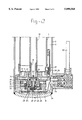
- FIG. 1 shows a longitudinal section of a first embodiment.
- FIG. 2 shows a longitudinal section of the bottom section of the embodiment according to FIG. 1 on a larger scale.
- FIG. 3 shows a longitudinal section of the bottom section of a second embodiment.
- the continuously variable twin-tube shock damper shown in FIG. 1 comprises a working cylinder, constructed as inner tube 1, an outer tube 2, a reservoir 3 between the working cylinder and the outer tube, a piston 4, which is movable within the working cylinder, a hollow piston rod 5 with fixing eye 5a, which can be connected to the sprung part of a wheel suspension unit, a cover 6 which closes off the working cylinder and the reservoir and forms a guide for the piston rod, a disc or foot valve housing 7 at the bottom of the working cylinder and a baseplate 8 with fixing eye 8a at the bottom of the outer tube.
- a central tube 10 the bottom end of which protrudes through the foot valve housing 7, extends through the piston 4.
- Openings 11 are made in the piston rod just above the piston 4, which openings connect the base above the piston to the interior of the piston rod 5.
- the top of the central tube 10 is located above the opening 11.
- the piston is provided with a valve housing 12, a valve seat 13 and a valve body 14, which is pushed onto the seat 13 by a spring 15.
- the components 12 to 15 form an upstream valve.
- Orifices 16 are made in the foot valve housing 7, which orifices are provided at the top of a spring-loaded upstream valve 17.
- said beaker-shaped piston has a section which has an axial orifice 20.
- the seat of the damping valve is located at the broadened underside of a tube section 9 screwed to the bottom of the central tube 10. The upper surface of the broadened section of said tube section 9 engages on the foot valve housing 7.
- a relatively small cylinder 22 is arranged so that it is movable with lateral play inside the beaker-shaped piston 19 and said small cylinder is pushed by a helical spring 23 towards the bottom surface of the base of the piston 19.
- Radial bores 24 are present in the uppermost part of the relatively small cylinder 22.
- a hollow piston 25 is movable inside the small cylinder 22 by means of a shaft-shaped section 27, which is movable in a valve shaft guide 26.
- One or more radial bores 28 have been made in the shaft-shaped section 25. Said bores are covered or uncovered--depending on the position of the piston shaft 27 relative to the guide 26.
- a helical spring 29 exerts an upward load on the piston 25.
- a coil 30 is arranged around the outside of the excitation chamber, which coil is a small distance away from a permanent magnet 31 and can be moved up and down by electrical excitation.
- the coil 30 is connected to the shaft section 27 of the hollow piston 25.
- the pressure in the excitation chamber 18 is controlled by a force equilibrium between a force which is the consequence of oil pressure on a surface the magnitude of the shaft section 27 of the control valve, a force generated by the spring tensioning of the spring 29 and a force which is the consequence of the electromagnetic force of the coil 30.
- Triggering of the coil 30 is effected from an electronic control unit via cable 32, conductor pins 33, line 34, laminated springs 35 and resilient tongues 36.
- the laminated springs 35 have a negligible influence on the vertical position of the coil 30.
- the shock damper also has a direction sensor 37 which, by means of a mechanical contact, or by measurement of a movement by means of coils in accordance with the Hall effect, or piezo-electrically, converts the pressure difference between the bottom of the cylinder and the reservoir 3 into a signal which indicates the direction of movement of the piston rod.
- the direction sensor 37 Via resilient pins 38 and conductor pins 39, the direction sensor 37 connects a cable 37 to the electronic control unit (ECU).
- ECU electronice control unit
- the pressure in the excitation chamber 18 is determined by the inflow of liquid via the passage 20 and the outflow of liquid via the radial bores 28.
- the pretensioning of the helical spring 29 and the cross-sectional surface area of the shaft 27 of the control valve determine the pressure in a highly controlled manner, liquid issuing from the excitation chamber.
- Said pressure can be so chosen that the damping force constitutes an average between the maximum and minimum damping force.
- the relatively small cylinder 22 and the valve shaft guide 26 have some radial play. Consequently, low-friction position control of the control valve 25, 26 can be achieved with low force from the exciter coil 30.
- the invention according to FIG. 3 differs from that according to FIGS. 1 and 2 in respect of the design of the damping valve and in that the beaker-shaped piston 19 has been dispensed with, as has the tube section 9 screwed into the bottom end of the central tube 10.
- the valve body 21 is constructed as an assembly of a number of thin spring steel discs (membranes), which are held together by a centring pin 21a with spindle retaining ring.
- the axial passage 20 is made in the centring pin.
- the discs are fixed with some play at their circumference between the housing 7 and the wall of the excitation chamber 18. Sealing is effected by means of an O-ring or the like in a groove in the wall of the excitation chamber.
- the damping liquid supplied via the central tube is fed via orifices 41, 16 in the housing 7 into the reservoir 3, at least when the valve body 21 has moved free of the seat beneath the housing.
- the servo-intensifying effect is achieved with a small surface area and a high pressure (up to 100 bar) above the valve body 21 and a large surface area and a low pressure (down to 4 bar) below the valve body 21.
- the functions which in the embodiment according to FIGS. 1 and 2 are fulfilled by the beaker-shaped piston 19 are taken over by the membrane valve body 21 in the embodiment according to FIG. 3.
- the side of the membrane package 21 which faces towards the excitation chamber 18 is subjected to the pressure which prevails in said chamber and which is controlled by the valve 25, 26 and the coil 30.
- the contact pressure of the package 21 against the seat at the bottom of the housing 7 can be controlled and consequently the resistance to flow of the liquid which flows from the openings 41 to the openings 16 proportionally to the electrical control current through the coil 30.
Landscapes
- Engineering & Computer Science (AREA)
- General Engineering & Computer Science (AREA)
- Mechanical Engineering (AREA)
- Physics & Mathematics (AREA)
- Fluid Mechanics (AREA)
- Fluid-Damping Devices (AREA)
- Vehicle Body Suspensions (AREA)
Applications Claiming Priority (3)
| Application Number | Priority Date | Filing Date | Title |
|---|---|---|---|
| NL9402150 | 1994-12-19 | ||
| NL9402150A NL9402150A (nl) | 1994-12-19 | 1994-12-19 | Continu variabele twee-pijpsschokdemper. |
| PCT/NL1995/000408 WO1996008950A2 (fr) | 1994-12-19 | 1995-11-30 | Amortisseur de chocs a deux tubes variable en continu |
Publications (1)
| Publication Number | Publication Date |
|---|---|
| US5890568A true US5890568A (en) | 1999-04-06 |
Family
ID=19865033
Family Applications (1)
| Application Number | Title | Priority Date | Filing Date |
|---|---|---|---|
| US08/849,783 Expired - Lifetime US5890568A (en) | 1994-12-19 | 1995-11-30 | Continuously variable twin-tube shock damper |
Country Status (8)
| Country | Link |
|---|---|
| US (1) | US5890568A (fr) |
| EP (1) | EP0797740B1 (fr) |
| JP (1) | JP2957704B2 (fr) |
| AU (1) | AU3883295A (fr) |
| DE (1) | DE69514938T2 (fr) |
| ES (1) | ES2143660T3 (fr) |
| NL (1) | NL9402150A (fr) |
| WO (1) | WO1996008950A2 (fr) |
Cited By (11)
| Publication number | Priority date | Publication date | Assignee | Title |
|---|---|---|---|---|
| WO2003040586A1 (fr) * | 2001-11-06 | 2003-05-15 | Koni B.V. | Amortisseur de chocs avec amortissement en fonction de frequence |
| US6851528B2 (en) * | 2001-10-29 | 2005-02-08 | Bombardier Recreational Products Inc. | Shock absorber with adjustable valving |
| US20100105506A1 (en) * | 2008-10-27 | 2010-04-29 | Claude Rointru | Hydraulic tensioner for a power transmission member having two modes of operation |
| US20100314209A1 (en) * | 2009-06-15 | 2010-12-16 | Gonzalez Jose L | Bicycle shock assemblies with plunger operated valve arrangement |
| CN102644688A (zh) * | 2012-04-24 | 2012-08-22 | 北京航空航天大学 | 一种基于着陆机构的腿式机械缓冲器 |
| US20130341140A1 (en) * | 2011-03-02 | 2013-12-26 | Honda Motor Co., Ltd. | Damper with variable damping force |
| CN104875834A (zh) * | 2014-02-27 | 2015-09-02 | 株式会社昭和 | 车辆高度调节设备 |
| US20150247494A1 (en) * | 2014-03-03 | 2015-09-03 | Xtreme Manufacturing, Llc | Method and system for a hydraulic cylinder |
| CN112855828A (zh) * | 2020-12-30 | 2021-05-28 | 哈尔滨工业大学 | 一种高桩码头的减震阻尼器 |
| US11293515B2 (en) * | 2003-07-08 | 2022-04-05 | Fox Factory, Inc. | Damper with pressure-sensitive compression damping |
| US20220412477A1 (en) * | 2021-06-25 | 2022-12-29 | Fox Factory, Inc. | Pressure balanced poppett with check |
Families Citing this family (8)
| Publication number | Priority date | Publication date | Assignee | Title |
|---|---|---|---|---|
| US6102170A (en) * | 1998-05-07 | 2000-08-15 | Tenneco Automotive Inc. | Passive anti-roll system |
| JP3583361B2 (ja) * | 1999-12-07 | 2004-11-04 | ツェットエフ ザックス アクチエンゲゼルシャフト | 調整され得る減衰力をもつ振動減衰器 |
| US6615960B1 (en) * | 2000-02-11 | 2003-09-09 | Maverick American Llc | Fluid damped shock absorber and method |
| KR101029050B1 (ko) * | 2008-07-17 | 2011-04-15 | 자화전자(주) | 고정밀 무소음형 전자식 팽창밸브 |
| DE102010035338B4 (de) * | 2010-08-24 | 2015-01-15 | Zf Friedrichshafen Ag | Schwingungsdämpfer mit verstellbarer Dämpfkraft |
| KR101103777B1 (ko) * | 2011-01-21 | 2012-01-06 | 자화전자(주) | 고정밀 무소음형 전자식 팽창밸브 |
| EP2742827B1 (fr) * | 2012-12-11 | 2015-03-11 | Karl-Heinz Brändle | Dispositif d'amortissement |
| JP6407073B2 (ja) * | 2015-03-20 | 2018-10-17 | 株式会社ショーワ | 車高調整装置 |
Citations (8)
| Publication number | Priority date | Publication date | Assignee | Title |
|---|---|---|---|---|
| GB621630A (en) * | 1945-10-22 | 1949-04-13 | Nevin Seasholtz Focht | Hydraulic shock absorber |
| DE3737173A1 (de) * | 1987-11-03 | 1989-05-18 | Dimec Digitale Mechanik Und El | Regelbarer stossdaempfer |
| WO1989009891A1 (fr) * | 1988-04-06 | 1989-10-19 | Koni B.V. | Amortisseur de chocs a tubes jumeles |
| WO1992012359A1 (fr) * | 1990-12-27 | 1992-07-23 | Koni B.V. | Amortisseur a deux tubes |
| WO1992016772A2 (fr) * | 1991-03-13 | 1992-10-01 | Alfred Teves Gmbh | Amortisseur bitube |
| EP0556925A2 (fr) * | 1992-02-18 | 1993-08-25 | Koni B.V. | Réglage d'amortisseur de véhicule |
| US5386893A (en) * | 1991-09-27 | 1995-02-07 | Alfred Teves Gmbh | Controllable hydraulic vibration absorber |
| US5400877A (en) * | 1991-03-13 | 1995-03-28 | Alfred Teves Gmbh | Two-tube shock absorber |
-
1994
- 1994-12-19 NL NL9402150A patent/NL9402150A/nl not_active Application Discontinuation
-
1995
- 1995-11-30 ES ES95938065T patent/ES2143660T3/es not_active Expired - Lifetime
- 1995-11-30 WO PCT/NL1995/000408 patent/WO1996008950A2/fr not_active Ceased
- 1995-11-30 AU AU38832/95A patent/AU3883295A/en not_active Abandoned
- 1995-11-30 DE DE69514938T patent/DE69514938T2/de not_active Expired - Lifetime
- 1995-11-30 JP JP8510775A patent/JP2957704B2/ja not_active Expired - Fee Related
- 1995-11-30 EP EP95938065A patent/EP0797740B1/fr not_active Expired - Lifetime
- 1995-11-30 US US08/849,783 patent/US5890568A/en not_active Expired - Lifetime
Patent Citations (8)
| Publication number | Priority date | Publication date | Assignee | Title |
|---|---|---|---|---|
| GB621630A (en) * | 1945-10-22 | 1949-04-13 | Nevin Seasholtz Focht | Hydraulic shock absorber |
| DE3737173A1 (de) * | 1987-11-03 | 1989-05-18 | Dimec Digitale Mechanik Und El | Regelbarer stossdaempfer |
| WO1989009891A1 (fr) * | 1988-04-06 | 1989-10-19 | Koni B.V. | Amortisseur de chocs a tubes jumeles |
| WO1992012359A1 (fr) * | 1990-12-27 | 1992-07-23 | Koni B.V. | Amortisseur a deux tubes |
| WO1992016772A2 (fr) * | 1991-03-13 | 1992-10-01 | Alfred Teves Gmbh | Amortisseur bitube |
| US5400877A (en) * | 1991-03-13 | 1995-03-28 | Alfred Teves Gmbh | Two-tube shock absorber |
| US5386893A (en) * | 1991-09-27 | 1995-02-07 | Alfred Teves Gmbh | Controllable hydraulic vibration absorber |
| EP0556925A2 (fr) * | 1992-02-18 | 1993-08-25 | Koni B.V. | Réglage d'amortisseur de véhicule |
Cited By (21)
| Publication number | Priority date | Publication date | Assignee | Title |
|---|---|---|---|---|
| US6851528B2 (en) * | 2001-10-29 | 2005-02-08 | Bombardier Recreational Products Inc. | Shock absorber with adjustable valving |
| WO2003040586A1 (fr) * | 2001-11-06 | 2003-05-15 | Koni B.V. | Amortisseur de chocs avec amortissement en fonction de frequence |
| US20050045440A1 (en) * | 2001-11-06 | 2005-03-03 | Kock Paul De | Shock absorber with frequency-dependent damping |
| CN100359202C (zh) * | 2001-11-06 | 2008-01-02 | 科尼公司 | 阻尼取决于频率的减震器 |
| US7395907B2 (en) | 2001-11-06 | 2008-07-08 | Koni B.V. | Shock absorber with frequency-dependent damping |
| US11293515B2 (en) * | 2003-07-08 | 2022-04-05 | Fox Factory, Inc. | Damper with pressure-sensitive compression damping |
| US20100105506A1 (en) * | 2008-10-27 | 2010-04-29 | Claude Rointru | Hydraulic tensioner for a power transmission member having two modes of operation |
| US9056650B2 (en) | 2009-06-15 | 2015-06-16 | Trek Bicycle Corporation | Bicycle shock assemblies with plunger operated valve arrangement |
| US9815517B2 (en) * | 2009-06-15 | 2017-11-14 | Trek Bicycle Corporation | Bicycle shock assemblies with plunger operated valve arrangement |
| US20100314209A1 (en) * | 2009-06-15 | 2010-12-16 | Gonzalez Jose L | Bicycle shock assemblies with plunger operated valve arrangement |
| US20130341140A1 (en) * | 2011-03-02 | 2013-12-26 | Honda Motor Co., Ltd. | Damper with variable damping force |
| US9303711B2 (en) * | 2011-03-02 | 2016-04-05 | Honda Motor Co., Ltd. | Damper with variable damping force |
| CN102644688B (zh) * | 2012-04-24 | 2014-08-13 | 北京航空航天大学 | 一种基于着陆机构的腿式机械缓冲器 |
| CN102644688A (zh) * | 2012-04-24 | 2012-08-22 | 北京航空航天大学 | 一种基于着陆机构的腿式机械缓冲器 |
| CN104875834A (zh) * | 2014-02-27 | 2015-09-02 | 株式会社昭和 | 车辆高度调节设备 |
| CN104875834B (zh) * | 2014-02-27 | 2018-09-25 | 株式会社昭和 | 车辆高度调节设备 |
| US9868624B2 (en) * | 2014-03-03 | 2018-01-16 | Xtreme Manufacturing, Llc | Method and system for a hydraulic cylinder |
| US20150247494A1 (en) * | 2014-03-03 | 2015-09-03 | Xtreme Manufacturing, Llc | Method and system for a hydraulic cylinder |
| CN112855828A (zh) * | 2020-12-30 | 2021-05-28 | 哈尔滨工业大学 | 一种高桩码头的减震阻尼器 |
| US20220412477A1 (en) * | 2021-06-25 | 2022-12-29 | Fox Factory, Inc. | Pressure balanced poppett with check |
| US12601414B2 (en) * | 2021-06-25 | 2026-04-14 | Fox Factory, Inc. | Pressure balanced poppett with check |
Also Published As
| Publication number | Publication date |
|---|---|
| DE69514938T2 (de) | 2000-06-08 |
| EP0797740A2 (fr) | 1997-10-01 |
| JPH10511166A (ja) | 1998-10-27 |
| EP0797740B1 (fr) | 2000-02-02 |
| NL9402150A (nl) | 1996-08-01 |
| JP2957704B2 (ja) | 1999-10-06 |
| ES2143660T3 (es) | 2000-05-16 |
| WO1996008950A3 (fr) | 1996-05-02 |
| WO1996008950A2 (fr) | 1996-03-28 |
| DE69514938D1 (de) | 2000-03-09 |
| AU3883295A (en) | 1996-04-09 |
Similar Documents
| Publication | Publication Date | Title |
|---|---|---|
| EP0797740B1 (fr) | Amortisseur de chocs a deux tubes variable en continu | |
| EP0517875B1 (fr) | Amortisseur a deux tubes | |
| US5386893A (en) | Controllable hydraulic vibration absorber | |
| US4673067A (en) | Adjustable shock absorber, especially for motor vehicles | |
| US4958704A (en) | Hydraulic telescopic shock absorber | |
| US6264015B1 (en) | Continuously variable single-tube shock absorber with bidirectional control valve | |
| US7156214B2 (en) | Vibration damper with amplitude-selective damping force | |
| KR101769148B1 (ko) | 감쇠력 조정식 완충기 | |
| EP0408631B1 (fr) | Amortisseur de chocs a tubes jumeles | |
| US5464079A (en) | Two-tube shock absorber | |
| KR100544488B1 (ko) | 감쇠력 가변 밸브 및 감쇠력 가변 밸브가 장착된 쇽 업소버 | |
| US5400877A (en) | Two-tube shock absorber | |
| WO1991016556A1 (fr) | Ensemble amortisseur reglable | |
| US6729446B2 (en) | Solenoid-operated driving apparatus and damping force control type hydraulic shock absorber using the same | |
| US5551540A (en) | Vibration damper and a vibration damper with a valve actuation device | |
| EP3633229B1 (fr) | Amortisseur | |
| US5558189A (en) | Adjustable hydraulic vibration damper | |
| US5769193A (en) | Telescoping vibration damper | |
| JPS645174B2 (fr) | ||
| JPH04503238A (ja) | 可変緩衝型シヨツクアブソーバ及びそのシステム | |
| KR100391419B1 (ko) | 차량용 쇽 업소버 | |
| US20010002639A1 (en) | Solenoid apparatus for use in hydraulic shock absorber | |
| CN109505911B (zh) | 一种车用减震阀 | |
| JPS6346295B2 (fr) | ||
| KR100776565B1 (ko) | 감쇠력 가변형 쇽 업소버 |
Legal Events
| Date | Code | Title | Description |
|---|---|---|---|
| AS | Assignment |
Owner name: KONI B.V., NETHERLANDS Free format text: ASSIGNMENT OF ASSIGNORS INTEREST;ASSIGNORS:DE KOCK, CORNELIS;DE KOCK, PAUL;REEL/FRAME:008633/0350 Effective date: 19970602 |
|
| STCF | Information on status: patent grant |
Free format text: PATENTED CASE |
|
| FEPP | Fee payment procedure |
Free format text: PAYOR NUMBER ASSIGNED (ORIGINAL EVENT CODE: ASPN); ENTITY STATUS OF PATENT OWNER: LARGE ENTITY |
|
| FPAY | Fee payment |
Year of fee payment: 4 |
|
| REMI | Maintenance fee reminder mailed | ||
| FPAY | Fee payment |
Year of fee payment: 8 |
|
| FPAY | Fee payment |
Year of fee payment: 12 |