US5890765A - Health care reclining chair - Google Patents
Health care reclining chair Download PDFInfo
- Publication number
- US5890765A US5890765A US08/659,998 US65999896A US5890765A US 5890765 A US5890765 A US 5890765A US 65999896 A US65999896 A US 65999896A US 5890765 A US5890765 A US 5890765A
- Authority
- US
- United States
- Prior art keywords
- chair
- assembly
- seat
- reclining
- frame
- Prior art date
- Legal status (The legal status is an assumption and is not a legal conclusion. Google has not performed a legal analysis and makes no representation as to the accuracy of the status listed.)
- Expired - Fee Related
Links
Images




Classifications
-
- A—HUMAN NECESSITIES
- A47—FURNITURE; DOMESTIC ARTICLES OR APPLIANCES; COFFEE MILLS; SPICE MILLS; SUCTION CLEANERS IN GENERAL
- A47C—CHAIRS; SOFAS; BEDS
- A47C1/00—Chairs adapted for special purposes
- A47C1/02—Reclining or easy chairs
- A47C1/031—Reclining or easy chairs having coupled concurrently adjustable supporting parts
- A47C1/034—Reclining or easy chairs having coupled concurrently adjustable supporting parts the parts including a leg-rest or foot-rest
- A47C1/035—Reclining or easy chairs having coupled concurrently adjustable supporting parts the parts including a leg-rest or foot-rest in combination with movably-coupled seat and back-rest
- A47C1/0352—Reclining or easy chairs having coupled concurrently adjustable supporting parts the parts including a leg-rest or foot-rest in combination with movably-coupled seat and back-rest characterised by coupled seat and back-rest slidingly movable in the base frame, e.g. by rollers
-
- A—HUMAN NECESSITIES
- A47—FURNITURE; DOMESTIC ARTICLES OR APPLIANCES; COFFEE MILLS; SPICE MILLS; SUCTION CLEANERS IN GENERAL
- A47C—CHAIRS; SOFAS; BEDS
- A47C1/00—Chairs adapted for special purposes
- A47C1/02—Reclining or easy chairs
- A47C1/031—Reclining or easy chairs having coupled concurrently adjustable supporting parts
- A47C1/034—Reclining or easy chairs having coupled concurrently adjustable supporting parts the parts including a leg-rest or foot-rest
- A47C1/035—Reclining or easy chairs having coupled concurrently adjustable supporting parts the parts including a leg-rest or foot-rest in combination with movably-coupled seat and back-rest
- A47C1/0355—Reclining or easy chairs having coupled concurrently adjustable supporting parts the parts including a leg-rest or foot-rest in combination with movably-coupled seat and back-rest actuated by linkages, e.g. lazy-tongs mechanisms
Definitions
- the present invention relates generally to a reclining chair and, more specifically, to a reclining chair for use in a health care environment having a reinforced chair frame structure and leg rest assembly which is capable of placing a seated occupant into a substantially flat layout position.
- Reclining chairs are widely used in a variety of residential and commercial applications and as such are adapted to provide reclining movement between the seat and seat back assemblies, tilting movement of the chair frame assembly relative to the base assembly, rocking or gliding movement of the chair frame assembly relative to the base frame assembly and extension and retraction of a leg rest assembly. These chairs are capable of placing the seated occupant in an infinite number of seated positions ranging from an upright position to a reclined position.
- a chair frame may experience a variety of extreme loading conditions on the side frames, chair arms and seat back when elderly or disabled patients sit down or get up from the reclining chair.
- the reclining mechanisms, tilting mechanisms and leg rest assembly may be loaded in extreme conditions by doctors or visitors leaning or sitting on the chair when it is situated in any of its various positions.
- the reclining chair when adapting a reclining chair for use in the health care environment, the reclining chair may be utilized as a means of transportation for the seated occupant. Typically, this has been accomplished by adapting a stationary base with a set of wheels such that the reclining chair is mobilized. This modification works adequately when moving the chair from location to location without a seated occupant. However, when the reclining chair is mobilized with a seated occupant therein, the seated occupant's feet may impede the forward mobility of the chair when in the upright position. In this situation, extending the leg rest does not provide an acceptable solution to this problem since it makes directional control of the reclining chair difficult, as well as places the seated occupant, who may be dressed in a hospital gown, in a potentially revealing position. Thus, it is also desirable to provide a mobile base which permits the reclining chair to be transported in a relatively effortless manner, locked into a immobile state, and which further supports the feet of an occupant seated in an upright position during movement of the reclining chair.
- reclining chairs known in the art have been adapted with a tilt linkage mechanism for tilting the chair frame relative to the base assembly.
- these mechanisms are operably coupled to the leg rest assembly and/or the seat assembly such that the chair frame is tilted concomitantly with the reclining motion of the seat back or the extension of the leg rest.
- it would be desirable to provide a chair frame assembly which may be tilted independent of other motion of the chair to place the seated occupant in an non-reclined, but rearwardly tilted position.
- a reclining chair which is adapted for use in the health care environment.
- a health care reclining chair which includes an improved swing link assembly for permitting the seat back assembly to recline to approximately 180° relative to the seat assembly to provide a substantially flat occupant-supporting surface such that the seat back provides a rearwardly extending cantilevered surface and the leg rest assembly provides a forwardly extending cantilevered surface from the chair frame assembly.
- the swing linkage mechanism includes a pair of front slide assemblies and a pair of rear swing linkage mechanisms which suspend and operably couple the seat assembly to the chair frame for providing the desired reclining motion.
- FIGS. 1A through 1D are perspective views of an exemplary health care reclining chair apparatus showing the various operative positions, including an upright position with the foot tray extended for transporting a seated occupant, an upright position with the leg rest assembly fully extended, a fully reclined position to provide a substantially flat occupant-supporting surface, and a fully reclined position where the chair frame is fully tilted to place a foot rest portion of the leg rest assembly slightly above a head rest portion of the seat back;
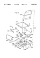
- FIG. 2 is an exploded perspective view of a reclining chair of a first preferred embodiment of the present invention with upholstery, springs, and other parts removed from the frame components for illustrating the integrated and interdependent association of these components;
- FIG. 3 is simplified side sectional view illustrating the mobile frame assembly, chair frame and primary tilt linkage which permits independent tilting of the chair frame relative to the base assembly;
- FIG. 4 is a simplified sectional view, similar to that shown in FIG. 3, with the chair frame tilted relative to the base assembly;
- FIG. 5 is a simplified sectional view of the improved swing linkage mechanism showing the seat assembly in the upright position in solid lines and in the reclined position in phantom lines;
- FIG. 6 is a sectional side view illustrating additional components of the present invention including the reinforcement bracing for interconnecting the front and rear cross-members of the chair frame assembly with the actuation mechanism, the leg rest assembly and the secondary tilt linkage mechanism, wherein the seat back is in the upright position and the leg rest assembly is in the retracted position such that the chair frame is not tilted relative to the base assembly;
- FIG. 7 is a simplified sectional view similar to FIG. 6 illustrating the seat back in the upright position and the leg rest assembly in the extended position such that the chair frame assembly is tilted relative to the base assembly;
- FIG. 8 is a simplified sectional view similar to FIG. 7 illustrating the chair frame with the seat back in a fully reclined position and the leg rest assembly extended such that the chair frame is tilted by the primary and secondary tilt linkage;
- FIG. 9 is an exploded perspective view of a rocking/reclining chair of a second preferred embodiment of the present invention which is adapted for use in a health care environment having upholstery, springs, and other parts removed from the frame components for illustrating the integrated and interdependent association of these components;
- FIG. 10 an exploded, detailed view of the front frame cross member of the chair shown in FIG. 9 illustrating a primary and secondary latching mechanism for enabling and disabling the rocking motion of the rocking/reclining chair on the mobile base;
- FIG. 11 is a simplified side view of the mobile base assembly shown in FIG. 9 having the secondary latching mechanism and the foot tray assembly in a stowed position;
- FIG. 12 is a front view of the base assembly shown in FIG. 11;
- FIG. 13 is a simplified side view of the rocking/reclining chair in a transportation mode showing the secondary pawl engaging the secondary racket plate to lock the chair frame in the upright position;
- FIG. 14 is a simplified sectional side view similar to that shown in FIG. 13 illustrating the seat assembly in a fully reclined position, the leg rest assembly in an extended position to provide a substantially flat occupant-supporting surface and the chair frame tilted rearwardly such that the primary pawl engages the primary racket sector to place a head rest portion of the seat back slightly below a foot rest portion of the leg rest assembly;
- FIG. 15 is a perspective view of a reclining chair of the present invention equipped with a retractable attendant tray positioned in a vertical, stowed position;
- FIG. 16 is a perspective view of the reclining chair shown in FIG. 15 having the attendant tray positioned in a horizontal use position;
- FIG. 17 is a view of the attendant tray looking from the front of the chair in a horizontal use position shown in solid lines and in a vertical stowed position shown in phantom lines;
- FIG. 18 is a view of the attendant tray looking from the side of the chair in a horizontal use position shown in solid lines and in a vertical, stowed position shown in phantom lines;
- FIG. 19 is a perspective view looking upwardly at the bottom surface of the attendant tray.
- a reclining chair adapted for use in a health care environment having a reinforced chair frame assembly and leg rest assembly and which incorporates a swing linkage mechanism to permit the seat back to be reclined approximately 180° relative to the seat.
- the health care reclining chair is provided with a mobile frame assembly having a fixed outer chair frame assembly operatively housing movable inner chair frame assembly.
- An independent tilting mechanism is interdisposed between the mobile frame assembly and the inner chair frame assembly for tilting the chair frame assembly relative to the base frame assembly.
- the present invention is directed to a combination reclining and platform rocking chair, hereinafter referred to as a reclining/rocking chair.
- the base assembly of the rocking/reclining chair is adapted with casters for providing a mobile base chair.
- the present invention also contemplates the use of other types of motion chairs, such as a wall proximity chair, a glider chair or a stationary rocking chair, in the health care environment.
- the functional and structural aspects of the present invention are shown.
- reclining chair 20 includes mobile frame assembly 22 supporting chair frame assembly 24.
- Leg rest assembly 26 is positionable between a retracted position as shown in FIG. 1A and an extended position as shown in FIGS. 1B through 1D.
- a seat assembly including seat back 28 and seat 30 are suspended within chair frame assembly 24 and operably coupled thereto for positioning between an upright position and a fully or "deep" reclined position.
- “deep recline” refers to the position where seat back 28 is substantially flat with respect to seat 30 such that the angle therebetween is approximately 180° as best seen in FIG. 1C.
- seat back 28 and seat 30 defines a substantially flat occupant-supporting surface which is substantially parallel to the floor surface, and thus provides a bed-like surface.
- reclining chair 20 is tiltable relative to mobile frame assembly 22 for changing the angular orientation thereof such that a head rest portion 39 formed at an upper end of seat back 28 is positioned slightly below a foot rest portion 27 formed at a distal end of leg rest assembly 26 when the seat assembly is in the deep recline position and the leg rest assembly is in the fully extended position.
- the position of an occupant seated in the reclining chair 20 shown in FIG. 1D may be referred to as the "trendelenburg" position.
- reclining chair 20 includes mobile frame assembly 22 supporting chair assembly 24 having outer side frame assembly 32 fixedly secured to mobile frame assembly 22 and inner side frame assembly 34 operably coupled to mobile frame assembly 22 by primary tilt linkage mechanism 36.
- Mobile frame assembly 22 includes a pair of base side rails 38 laterally spaced by a pair of cross members 40 defining a substantially rectangular base frame.
- Base side rails 38 are preferably formed out of angle iron having a horizontal flange for supporting outer side frame assembly 32 from beneath and a horizontal flange to which outer side frame assembly 32 can be secured.
- a set of four casters 42 extend downwardly from the corners of mobile frame assembly and are operably coupled thereto such that casters 42 are able to rotate about a vertical axis to enable reclining chair 20 to be easily pushed and steered in any direction.
- Casters 42 are equipped with a locking feature for disabling the mobility of base assembly 22.
- casters 42 could be replaced with stationary leg portions for providing a stationary health care reclining chair similar to the mobile health care reclining chair disclosed as the herein as the first preferred embodiment.
- Outer side frame assembly 32 includes outer side panel 44 having lower frame member 48 extending laterally outwardly from the bottom edge of outer side panel 44, upper frame member 50 extending laterally outwardly from an upper edge of outer side panel 44, and forward frame member 52 disposed along a front edge of outer side panel 44.
- angle brace 54 and support block 56 are disposed between lower frame member 48 and outer side panel 44 to further stiffen outer frame assembly 32.
- casters 42 are provided with a threaded stud (not shown) which extends upwardly through a clearance hole formed through horizontal flange 38 and is threadingly engaged with a tee nut disposed in a complementary hole formed in lower frame member 48.
- lower frame member 48 is clamped between base side rail 38 and angle brace 54 clamp to provide additional rigidity to outer side panels 44.
- Contour block 58 is disposed along a rear edge of outer side panel 44 to provide the desirable look and contour to outer side frame assembly 32 when upholstered.
- Cutout portion 60 formed in outer side panel 44 reduces the weight of reclining chair 20, while providing easier access to the surface underneath upper frame member 50 to facilitate upholstering of outer side frame assembly 32.
- Clearance hole 62 is formed in outer side panel 44 to allow unobstructed motion of drive rod 78 during tilting movement of inner side frame assembly 34 relative to outer side frame assembly 32.
- inner side frame assembly 34 includes inner side panels 64 interconnected and laterally spaced by front and rear inner frame cross members 66, 68.
- front inner frame cross member 66 is a multi-piece assembly including lower cross member segment 70, end member segments 72 extending upwardly opposite lateral ends of cross member segment 70, and central segment 74 provided substantially midway between end member segments 44 and support shaft 76 extending laterally between end member segments 70 and secured to central segment 74.
- Drive rod 78 is suspended from and operably coupled to inner side panels 64 for rotation therein.
- Actuation handle 80 is disposed on an end of drive rod 78 to permit rotational manipulation thereof.
- front and rear inner frame cross members 66, 68 are formed as metal components and are assembled utilizing a knock down or integrated construction technique.
- a more detailed description of these components and this construction technique can be found in U.S. Pat. No. 5,435,621 entitled “Modular Reclining Chair and Method” which is commonly owned by the assignee of the present invention and the disclosure of which is expressly incorporated by reference herein.
- Inner side frame assembly 34 is operably connected to mobile frame assembly 22 through primary tilt linkage mechanism 36 which includes tilt drive rod 88 supported from base side rails 38 for rotational movement, tilt side rails 90 pivotally coupled to base side rails 38 and tilt linkage 92 operably coupling tilt drive rod 88 to tilt side rails 90.
- Handle 94 is disposed on an end of tilt drive rod 88 for permitting rotational manipulation thereof to actuate primary tilt linkage mechanism 36.
- handle 94 is provided with a sleeve portion extending laterally inward to slidingly receive tilt drive rod 88 such that handle 94 may be disposed beneath chair frame assembly 24 when not in use.
- Handle 94 is also provided with a stop member (not shown) to prevent separation of handle 94 from drive rod 88.
- Tilt side rail 90 is operably coupled to base side rails 38 at support 96 for pivotal movement about pivot 98 in response to actuation of tilt linkage 92.
- Tilt linkage 92 includes a pair of linkage assemblies each having drive link 100 secured to tilt drive rod 88 for rotation therewith.
- Tilt link 102 is pivotally connected to tilt side rail 90 at pivot 104 and pivotally connected to drive link 100 at pivot 106 such that a forward edge of tilt link 102 engages tilt drive rod 88 for defining a positive stop for tilt linkage 92.
- Tilt linkage 92 further includes a toggle mechanism for providing a mechanical assistance to tilt linkage 92.
- the toggle mechanism includes toggle drive link 108 secured to tilt drive rod 88 for rotation therewith, linear spring 110 secured to rear base cross member 40 and extending forwardly therefrom, and toggle link 112 interconnecting toggle drive link 108 with spring 110 such that counterclockwise rotation of tilt drive rail 88 positions pivot 106 in an overcenter condition relative to pivots 98 and 104 to urge tilt linkage mechanism into a tilted position.
- primary tilt linkage mechanism 36 is in a lowered position such that the angular orientation of outer side frame assembly 32 and inner side frame assembly 34 correspond.
- toggle link 112 is in an overcenter condition so as to urge tilt drive rod 88 in a clockwise direction and thus maintain primary tilt linkage mechanism in the forward or non-tilted position.
- Chair support bracket 142 extends rearwardly from lower cross member segment 70 and has foot portion 144 extending downwardly to engage front base cross member 40 to define a mechanical stop in the non-tilted position which transfers load applied to seat 30 through front inner frame cross member 66 and stop member 142 into base assembly 22.
- foot member 144 is made from an elastic material for allowing compression loading of the various joints and pivotal connections in reclining chair 20, thereby relieving the loads applied to drive rod 76.
- tilt drive rod 88 has been rotated in the counterclockwise direction causing drive link 100 and tilt link 102 to urge the front portion of tilt side rails 90 upwardly so as to rotate about pivot 98 and cause inner side frame assembly 34 to tilt relative to outer side frame assembly 32 and base assembly 22.
- toggle link 112 passes through an overcenter condition so as to provide mechanical assistance during the tilting actuation of primary tilt linkage mechanism 36.
- Drive link 100 and tilt link 102 continue to rotate side rails 90 about pivot 98 until a front edge of tilt link 102 below pivot 106 engages drive rod 88 to define a positive mechanical stop.
- primary tilt linkage mechanism 36 provides approximately 7° of rearward tilt of inner side frame assembly 34 relative to outer side frame assembly 32 as indicated at ⁇ 1 in FIG. 4.
- seat 30 and swing linkage mechanism 86 of the present invention illustrates the range of reclining motion achieved between seat back 28 and seat 30.
- seat 30 is of the type disclosed in U.S. Ser. No. 08/319,672 entitled "Recliner Chair Seat Assembly And Method Of Upholstering” filed on Oct. 12, 1994, which is commonly assigned to the assignee of the present invention and the disclosure of which is hereby expressly incorporated by reference herein.
- Metal seat frame 30 is well-suited for use in the health care environment in that a seat cushion (not shown) can be quickly and easily replaced should it become damaged or soiled during use.
- metal seat 30 is readily adaptable to a wide range of cushion thicknesses which permit a wide range of seat heights to be accommodated. This is particularly advantageous in the health car environment where a relatively high seat height is desirable to facilitate getting into and out of the reclining chair.
- seat 30 is supported at a forward portion by support shaft 76 and at a rearward portion by inner side panel 64. More specifically, the side rails of seat 30 are adapted to receive front slide assembly 84 which includes front slide bracket 114 having lost motion slot 116 formed therein for guiding the fore and aft motion of seat 30 on support shaft 76. Lost motion slot 116 is of sufficient length to permit a full range of travel for seat 30 during reclining motion thereof and accordingly does not function as a mechanical stop.
- Rear swing linkage mechanism 86 includes rear attachment link 118 secured to inner side panel 64, rear swing link 120 pivotally connected at a first end to attachment link 118 and operably coupled to seat 30.
- an upstanding post formed on the rear portion of seat 30 is pivotally connected at pivot 122 to rear swing link 120.
- rear swing link 120 is operably connected to seat 30 through rear slide mechanism 124.
- seat back 28 is releasably secured to an upper portion of rear swing link 120.
- rear swing link 120 permits seat back 28 to be reclined into a substantially flat position relative to seat 30. More specifically, as seat back 28 is reclined relative to seat 30, rear swing link 120 rotates about pivot 122 causing the rear portion of seat 30 to move forwardly and upwardly about an arcuate path defined by pivot 122 (shown in FIG. 5 as A 1 ). As seat 30 moves upwardly and forwardly, front slide brackets 114 slides upwardly and forwardly on support shaft 76. In order for the seat assembly to achieve a substantially flat position, the geometry of rear swing link 120 must be such to allow pivot 126 to achieve an overcenter condition relative to a line drawn between pivot 122 and front support shaft 76.
- swing linkage mechanism 86 are such that the arc, A 1 , is tangential with, or in the alternative does not intersect with an arc drawn about the centerline of support shaft 76 through pivot 126 (shown in FIG. 5 as A 2 ) when the seat assembly is in the fully reclined position.
- swing linkage mechanism 86 function as a sliding-block linkage mechanism to permit a full range of motion of seat 30 relative to rear swing link 120.
- Rear slide mechanism 124 is operably coupled between rear swing link 120 and seat 30 to define a deep recline limit of the reclining movement of the seat assembly position. More specifically, slide member 128 is pivotally coupled to a lower end of rear slide link 120 and has elongated slot 130 formed therein. Retainer 132 disposed within the slot 130 is secured to seat 30 such that slide 128 reciprocates relative thereto. When seat back 28 reaches the deep recline position, retainer 132 engages the rear portion of slot 130 to provide a positive mechanical stop, thus limiting further reclining motion of seat back 28 relative to seat 30.
- rear slide mechanism 124 may be adapted to provide an adjustable frictional resistance to reclining movement of seat back 28 relative to seat 30.
- the upright limit of reclining movement of the seat assembly is defined by the engagement of a rearward edge of rear swing link 120 with rear inner cross member 68 as best seen in FIG. 6.
- reinforcement bracing 134 is interconnected between drive rod 78 and front and rear inner cross members 66, 68 and includes a pair of laterally spaced drive shaft supports which are journally connected to drive rod 78 and extend forwardly to front inner frame cross member 68 and rearwardly to rear inner frame cross member 68. More specifically, front drive rod support 138 is journally connected to drive rod 78 at a rear end thereof and rigidly secured to a middle portion of corresponding front support arm 140 while front support arm 140 extends between a top portion of support shaft 76 and front cross member segment 70.
- reinforcement bracing 134 include rear drive shaft support 146 having a forward end journally connected to drive rod 76 and a reward end rigidly secured to a lower flange of rear inner frame cross member 68. In this manner, reinforcement bracing 134 ties front and rear cross frame members 66, 68 with drive rod 28 to further strengthen and stiffen inner side frame assembly 34 of reclining chair 20.
- a more detailed description of the components of reinforced bracing 134 can be found in U.S. application Ser. No. 08/552,614 entitled “Linear Actuation Drive Mechanism For Power-Assisted Chairs" filed on Nov. 3, 1995 which is commonly owned by the assignee of the present invention and the disclosure of which is expressly incorporated by reference herein.
- leg rest assembly 26 of reclining chair 20 is illustrated and includes pantograph linkage 82 having leg rest board 148 and ottoman board 150 secured to a portion thereof.
- Pantograph linkage 82 is journally supported from support shaft 76 by curved swing link 152 and operably coupled to drive rod 78 through long support link 154.
- long support link 154 is designed to transfer very heavy loads resulting from a person leaning or sitting on leg rest board 148 or ottoman board 150 through pantograph linkage 82 into drive rod 78. These heavy loads are transferred into inner chair frame assembly 34 by reinforcement bracing 134 which prevents undesirable deformation of drive rod 78.
- Leg rest assembly 26 is positionable from a retracted position as shown in FIG.
- Leg rest assembly 26 further includes a spring-assist toggle assembly 156 which cooperate with pantograph linkage 82 to facilitate protraction and retraction of leg rest assembly 26.
- Leg rest board 148 is readily adaptable to receive various upholstering and/or cushions to match the cushion thickness and seat height utilized with seat 30 for placing a seated occupant in a comfortable position when leg rest assembly is in the extended position.
- ottoman panel 150 is stowed behind leg rest board 148 when leg rest assembly is in the retracted position, and thus is not readily adaptable to receive various upholstering and/or cushion thickness.
- height adjustment of ottoman board 150 may be accommodated with an ottoman linkage having a selectable height feature.
- a presently preferred leg rest assembly is disclosed in U.S. application Ser. No. 08/659,798 entitled “Dual Leg Rest Assembly Having Selectable Height Ottoman" filed on Jun. 7, 1996 which is commonly owned by the assignee of the present invention is preferred and the disclosure of which is expressly incorporated by reference herein.
- Secondary tilt assembly 160 is interconnected between tilt side rail 90 and seat 30 for tilting inner side frame assembly 34 relative to primary tilt linkage mechanism 36, i.e., rotating inner side frame assembly 34 about pivot point 162.
- Secondary tilt assembly 160 further includes main pivot brackets 172 attached to base side rails 38 and main pivot mount 174 secured to an inner surface of inner side panels 64 for pivotally connecting inner side frame assembly 34 to tilt side rail 90 of primary tilt linkage mechanism 36.
- Secondary tilt assembly 160 is operably coupled to front slide assembly 84 for causing tilting movement in response to reclining movement of seat back 28 relative to seat 30 and includes a generally straight lift link 164 pivotally connected at a rear portion of front slide bracket 114 at an upper end thereof and pivotally connected to lift lever 166 at a lower end thereof. Secondary tilt assembly 160 is also operably coupled to drive rod 78 for causing tilting movement in response to rotation thereof, and further includes lift lever 166 pivotally connected at pivot point 168 intermediate the first and second ends thereof to front pivot bracket 170 which is secured to tilt side rails 90. The second end of lift lever 166 is operably coupled to drive rod 78 such that rotation thereof causes tilting movement of inner side frame assembly 34.
- reclining chair 20 is illustrated in a non-tilted, non-reclined position such that seat 30 is supported by support shaft 76 by main pivot bracket 172.
- tilting movement is induced as seat back 28 is reclined with respect to seat 30.
- Lift link 164 rotates about its pivotal connection in a clockwise direction to urge the front of inner side frame assembly 34 upward so as to tilt about pivot point 174.
- Additional tilting of the inner side frame assembly 34 can be achieved by rotation of drive rod 78 in a counterclockwise direction which rotates lift lever 166 in a counterclockwise direction about bracket pivot 168 to urge lift link 164 in an upwardly direction, thereby further tilting inner side frame assembly 34 relative to primary tilt linkage mechanism 36.
- the total tilting movement effectuated by reclining seat back 28 and actuation of drive rod 78 is the sum tilting movement achieved by each independent tilting movement heretofore described.
- the tilting movement of inner side frame assembly 34 effectuated by reclining of seat back 28 is approximately 3° (not shown independently), and the tilting movement of inner side frame assembly effectuated by rotation of drive rod 78 is approximately 6° as indicated as ⁇ 3 in FIG. 7.
- secondary tilt assembly 160 enables reclining chair 20 to be independently and cumulatively tilted a total of approximately 9° as indicated as ⁇ 2 in FIG. 7.
- primary tilt linkage mechanism 36 which provides approximately 7° of tilt between inner side frame assembly 34 and mobile frame assembly 22 as indicated by ⁇ 1 in FIG.
- primary tilt linkage mechanism 36 and secondary tilt assembly 160 enables reclining chair 20 to be independently and cumulatively tilted a total of approximately 16°.
- actuation of primary tilt linkage mechanism 36 and secondary tilt assembly 160, in combination with deep recline swing linkage mechanism 86, enables a seated occupant to be laid in a substantially flat position parallel with the floor or inclined thereto such that their head is positioned slightly below their feet in a trendelenburg position.
- 08/429,104 is described with particular reference to a reclining chair having a wooden seat and a swing link mechanism adapted therefor, one skilled in the art would readily recognize that the invention disclosed therein is adaptable to include a metal seat assembly with certain changes, modifications and/or adaptations to the rear swing linkage mechanism without departing from the spirit and scope of the present invention. Likewise, the present invention is equally adaptable to a motion chair having a wooden seat assembly with certain changes, modifications and/or adaptations to the rear swing linkage mechanism without departing from the spirit and scope thereof.
- rocking/reclining chair 220 includes mobile base assembly 222, chair frame assembly 224, leg rest assembly 226 and a seat assembly having seat back 228 and seat 230.
- Chair frame assembly 224 is operably coupled to mobile base assembly 222 for rocking movement thereon.
- side frame panel 232 receives contoured rocker block 234 on a lower inner surface thereof.
- the bottom surface of rocker block 234 is curved and engages an upper surface of mobile base assembly 222 to permit rocking movement of chair frame assembly 224 thereon.
- rocker block 234 is interconnected to base assembly 222 by double coil spring rocker assembly 236 for permitting balanced rocking movement of chair frame assembly 224 with respect to base assembly 222 and further for urging chair frame assembly 224 into a substantially upright neutral position.
- Spring rocker assembly 236 further provides a limit for rearward and/or forward rocking movement of chair frame 224 relative to base assembly 222.
- a presently preferred design of spring rocker assembly 236 is disclosed in U.S. application Ser. No. 08/322,788 entitled "Rocking/Reclining Chair Having Limit Means and Noise Suppression Means" filed on Oct. 13,1995 which is commonly owned by the assignee of the present invention and which is expressly incorporated by reference herein.
- Chair frame assembly 224 includes side frame panel 232 interconnected and laterally spaced by front and rear frame cross members 240, 242.
- front frame cross member 240 is a multi-piece assembly identical to front inner frame cross member 66 described previously with reference to the first preferred embodiment of the present invention and includes support shaft 328.
- Drive rod 244 is suspended from and operably coupled to side frame panel 232 for rotation therein.
- Actuation handle 246 is disposed on an end of drive rod 244 to permit rotational manipulation thereof.
- mobile base assembly 222 includes base side rails 248 interconnected and laterally spaced by front and rear base cross members 250, 252 to define a substantially rectangular base assembly.
- a pair of rearwardly extending flanges 254 are secured to rear base cross member 252 and receive a pair of rear casters 256.
- front casters 258 are secured to a bottom surface of front base frame cross member 250 for mobilizing base assembly 222.
- front casters 258 are secured to base assembly 222 so that the wheels thereof do not rotate about a vertical axis.
- rear casters 256 are capable of rotating about a vertical axis to facilitate steering of chair 220 on mobile base assembly 222.
- rear casters 256 include a locking feature which disables the mobile aspect of base assembly 222.
- Mobile base assembly 222 may further optionally include foot tray assembly 260 which provides a pullout surface in front of and below seat 230 when rocking/reclining chair 220 is in the upright position with leg rest assembly 226 retracted.
- foot tray assembly 260 allows the feet and legs of a seated occupant to rest on a portion of mobile base assembly 222 during transportation without impeding the mobility of chair 220 or requiring extension of leg rest assembly 226.
- Foot tray assembly 260 includes rectangular foot tray frame 262 having support rails 264 laterally spaced by front and rear cross members 266, 268.
- Foot tray board 270 is disposed within and supported by foot tray frame 262. As presently preferred, the upper surface of foot tray board 270 has a non-slip surface thereon to provide additional safety.
- Foot tray frame 262 is suspended from mobile base assembly 222 by a pair of C-shaped foot tray brackets 272 secured to a lower surface of front base cross member 250.
- nylon inserts 274 are disposed within foot tray bracket 272 which receives foot tray frame 262 to facilitate sliding movement therein.
- foot tray frame 262 and foot tray board 270 are extendable and retractable from mobile base assembly 222 in a pullout manner.
- a pair of casters 276 are secured to the front edge of front cross member 268 to support front tray assembly 260 in the extended position.
- foot tray frame 262 is angularly oriented with respect to mobile base assembly 222 in a forwardly and upwardly direction as indicated by the angle ⁇ which is approximately 3°.
- the angular orientation of foot tray assembly 260 facilitates manipulation of mobile base assembly 222 by eliminating a point of contact between the floor and casters 276 when foot tray assembly 260 is unloaded or lightly loaded.
- Mobile base assembly 222 also includes primary latching mechanism 280 and secondary latching mechanism 282 pivotally connected to front base cross member 250 on an upper surface thereof.
- primary latching mechanism 280 includes primary pawl 284 and arcuate ratchet sector 286 formed on a central member of front frame cross member 240.
- a plurality of teeth 288 are formed on the arcuate surface of primary ratchet sector 286.
- Primary pawl 284 is pivotally positionable about pin 290 with respect to ratchet teeth 288 between a disengaged (released) position as shown in FIG. 13 for permitting normal rocking action of chair 220, and an engaged (locked) position as shown in FIG.
- Primary pawl 284 is urged forwardly or biased towards primary ratchet 286 by torsional spring 292.
- Primary latching mechanism 280 further includes release member 294 which operably interconnects primary pawl 284 with drive rod 244 such that primary pawl 284 is disengaged from primary ratchet sector 286 when drive rod 244 is in its clockwise-most position as seen in FIGS. 13 and 14. As drive rod 244 is rotated counterclockwise, primary latching mechanism 280 permits primary pawl 284 to pivot into engagement with primary ratchet sector 286 for placing chair 220 in the locked position.
- release member 294 pivots primary pawl 284 out of engagement from primary ratchet sector 286, thus enabling rocking movement of chair 220.
- a presently preferred primary latching mechanism is further disclosed and illustrated in U.S. application Ser. No. 08/322,789 entitled “Pawl and Ratchet Assembly” filed on Oct. 13, 1994 which is commonly owned by the assignee of the present invention and the disclosure of which is expressly incorporated by reference herein.
- Secondary latching mechanism 282 is provided on mobile base assembly 222 for locking out the rocking motion of chair 220 during mobile transportation thereof.
- secondary latching mechanism 282 includes secondary pawl 296 pivotally connected through pin 290 to an upper surface of front base cross member 250 and biased by torsional spring 292.
- Secondary ratchet plate 298 have a pair of rearwardly tapered edges formed thereon that terminate at a notch and is secured to and extends from primary ratchet sector 286. More specifically, a pair of apertures 300 are formed through the sidewalls of primary ratchet sector 286 and receive threaded fasteners 302.
- Secondary ratchet plate 298 is positioned laterally outboard of primary ratchet sector 286 by spacer bushings 304. As presently preferred, threaded fasteners 302 extend through both walls of primary ratchet sector 286 shown in FIG. 10. Secondary pawl 296 is pivotally positioned into engagement with the notch formed in secondary ratchet plate 298 for locking out the rocking motion of chair frame 224 similar to that described with respect to primary latching mechanism 280.
- Secondary latching mechanism 282 includes a linkage mechanism for selectively positioning secondary pawl 296. More specifically, as best seen in FIG. 11, the linkage mechanism includes release link 306 pivotally connected at a first end to secondary pawl 296 and pivotally connected at a second end to rocker link 308 which is secured to a forward surface of rear base cross member 252 by rocker bracket 310 for pivotal motion thereon. Similarly, drive link 312 is pivotally coupled to a rearward surface of rear base cross member 352 by drive bracket 314.
- Drive link 316 interconnects a lower portion of drive link 312 with a lower portion of rocker link 308.
- a rearwardly extending portion of drive link 312 is utilized as an actuation pedal for secondary latching mechanism 282. As best seen in FIG.
- Assist link 318 is pivotally coupled to a mid-portion of release link 306 at a first end thereof and is attached to assist spring 320 at a second end thereof.
- Assist spring 320 extends from a second end of assist link 318 to front base cross member 250 for providing mechanical assistance to the actuation of secondary latching mechanism 282.
- chair 220 includes reinforcement bracing 322 interconnected between drive rod 244 and front and rear frame cross member 240, 242 which is substantially similar to reinforcement bracing 134 described and illustrated with respect to the first preferred embodiment of the present invention. More specifically, a pair of lateral spaced drive shaft supports are generally connected to drive rod 244 and extend forwardly to front frame cross member 240 and rearwardly to rear frame cross member 242.
- Front drive rod support 324 is journally connected to drive rod 244 at a rear end and rigidly secured to a middle portion of corresponding front support arm 326 which is secured at an upper end to support shaft 328 and at a lower end to front cross member segment 230.
- reinforcement bracing 322 includes rear drive rod support 332 having a forward end journally connected to drive rod 244 and a rearward end rigidly secured to a lower flange of rear frame cross member 242.
- the swing linkage mechanism of chair 220 is identical to the swing linkage mechanism described with respect to the first preferred embodiment and includes front slide assembly 334 and rear swing linkage mechanism 336. As previously described, the geometry of front slide assembly 334 and rear swing linkage mechanism 336 permits seat back 228 to be reclined into a substantially flat position relative to seat 230.
- leg rest assembly 226 of chair 220 is substantially identical to leg rest assembly 26 of the first preferred embodiment of the present invention and includes a pair of pantograph linkages 338 having leg rest board 340 and ottoman board 342 secured to a portion thereof.
- Pantograph linkage 338 is operably coupled between support shaft 328 and drive rod 224 so as to be positionable from a retracted position as shown in FIG. 13 into an extended position as shown in FIG. 14 through the manipulation of drive rod 244.
- Leg rest assembly 226 further includes spring assist toggle assembly 344 which cooperates with pantograph linkage 338 to facilitate protraction and retraction of leg rest assembly 226.
- Rocking/reclining chair 220 is positionable through a range of motion from an upright position where the seat assembly is in a non-reclined position and the chair frame assembly is in a neutral, non-tilted position as illustrated in FIG. 13, to a fully reclined position which places a seated occupant in a substantially flat position and a fully tilted or trendelenburg position such that their head is positioned slightly below their feet as best illustrated in FIG. 14. While chair 220 has been described to include mobile base assembly 222, one skilled in the art would readily recognize that a stationary base assembly similar to the base assembly disclosed in U.S. application Ser. No. 08/322,789 entitled "Pawl & Ratchet Assembly" previously identified and incorporated by reference herein could be adapted for use in the present invention.
- reclining chair 20 in accordance with the first preferred embodiment is illustrated including fixed outer side frame assembly 32 which allows various medical related equipment, such as trays, I.V. poles, monitoring equipment and the like, to be attached to reclining chair 20 without adversely affecting the reclining or tilting movement thereof.
- Attendant tray 400 is secured to an upper portion of outer side frame assembly 32 and is positionable between a substantially vertical, non-use position as shown in FIG. 15 and a horizontal, use position as shown in FIG. 16.
- Attendant tray 400 includes tray top 402 operably coupled to mount bracket 404 for relative rotational motion.
- a pair of hinges 406 are disposed along an upper edge of mount bracket 404 and secure to a bottom surface of tray top 402 along an inboard edge.
- the bottom surface of tray top 402 also has recessed portion 408 formed therein for receiving brace 410 which is secured thereto by hinge 412. In this manner, brace 410 is received within the bottom surface of tray top 402, thereby permitting tray top 402 to collapse directly against outer side frame assembly 32.
- tray top 402 is fabricated out of molded plastic, a suitable wood or coated composite board, while mount bracket 404, hinges 406, brace 410, and hinge 412 are formed out of aluminum. Although it is contemplated that other materials providing the proper structural characteristics could also be utilized.
- Mount bracket 404 is secured to outer side frame assembly 32 by threaded fasteners 416 which extend through mount bracket 404 into the side panel.
- brace 410 By hingedly securing brace 410 to tray top 402, attendant tray 400 is gravity operated. More specifically, if attendant tray 400 is in the vertical, stowed position, the seated occupant or an attendant therefor merely lifts an outer edge of tray top 402 upwardly so as to rotate tray top 402 about hinges 406. As tray top 402 reaches the horizontal position, gravity urges brace 410 to rotate downward about hinge 412 and into a substantially vertical position to support tray top 402.
- a pair of protuberances in the of shape hemispherical discs 414 are situated on either side of brace 410 to facilitate manipulation of brace 410 into the proper center position for supporting tray top 402.
- Attendant tray 400 is easily stowed by again lifting slightly upwardly on tray top 402 to release brace 410 from mount bracket 404 and to clear protuberances 414.
- Brace 410 is manipulated slightly laterally about hinge 412. Once brace 410 is past a vertical orientation, gravity urges tray top 402 downwardly, thus collapsing brace 410 into recess portion 408 of tray top 402.
- Tray top 402 is shaped to facilitate the manipulation of attendant tray 400 while maximizing the usable surface are thereof. More specifically, the forward and rearward portions of tray top 402 is sufficiently sized to provide a usable table top. The center portion of tray top 402 is contoured slightly inward toward reclining chair 20 to enable a occupant seated therein to reach beneath tray top 402 when it is in the horizontal, use position to access brace 410 for placing attendant tray 400 back into the substantially vertical, stowed position.
- the present invention is directed to a motion chair which is specifically adapted to and addresses the needs of an article of furniture for use in a health care environment. While the foregoing discussion discloses and describes various exemplary embodiments of the present invention, one skilled in the art will readily recognize from such discussion, and from the accompanying drawings and claims, that various changes, modifications and adaptations can be made therein without departing from the spirit and scope of the invention as set forth in the following claims.
Landscapes
- Health & Medical Sciences (AREA)
- Dentistry (AREA)
- General Health & Medical Sciences (AREA)
- Chairs For Special Purposes, Such As Reclining Chairs (AREA)
Priority Applications (5)
| Application Number | Priority Date | Filing Date | Title |
|---|---|---|---|
| US08/659,998 US5890765A (en) | 1996-06-07 | 1996-06-07 | Health care reclining chair |
| AU34795/97A AU3479597A (en) | 1996-06-07 | 1997-06-06 | Health care reclining chair |
| PCT/US1997/009867 WO1997046143A1 (fr) | 1996-06-07 | 1997-06-06 | Fauteuil inclinable pour soins |
| CA002255687A CA2255687C (fr) | 1996-06-07 | 1997-06-06 | Fauteuil inclinable pour soins |
| GBGB9825968.2A GB9825968D0 (en) | 1996-06-07 | 1998-11-26 | Health care reclining chair |
Applications Claiming Priority (1)
| Application Number | Priority Date | Filing Date | Title |
|---|---|---|---|
| US08/659,998 US5890765A (en) | 1996-06-07 | 1996-06-07 | Health care reclining chair |
Publications (1)
| Publication Number | Publication Date |
|---|---|
| US5890765A true US5890765A (en) | 1999-04-06 |
Family
ID=24647712
Family Applications (1)
| Application Number | Title | Priority Date | Filing Date |
|---|---|---|---|
| US08/659,998 Expired - Fee Related US5890765A (en) | 1996-06-07 | 1996-06-07 | Health care reclining chair |
Country Status (5)
| Country | Link |
|---|---|
| US (1) | US5890765A (fr) |
| AU (1) | AU3479597A (fr) |
| CA (1) | CA2255687C (fr) |
| GB (1) | GB9825968D0 (fr) |
| WO (1) | WO1997046143A1 (fr) |
Cited By (40)
| Publication number | Priority date | Publication date | Assignee | Title |
|---|---|---|---|---|
| US6119980A (en) * | 1997-04-02 | 2000-09-19 | Reynard Aviation Limited | Seat |
| US20040004383A1 (en) * | 2002-05-31 | 2004-01-08 | Ligonniere Laurent | Seat which can be converted into a couchette with a deformable armrest |
| US20040020708A1 (en) * | 2000-04-03 | 2004-02-05 | Szabela William A. | Electric steering apparatus |
| US6691346B2 (en) | 1999-12-29 | 2004-02-17 | Hill-Rom Services, Inc. | Foot controls for a bed |
| US6739006B2 (en) | 1997-11-07 | 2004-05-25 | Hill-Rom Services, Inc. | Head section support for a surgical table apparatus |
| US6754923B2 (en) | 1997-11-07 | 2004-06-29 | Hill-Rom Services, Inc. | Leg section support for a surgical table |
| US20060087158A1 (en) * | 2004-08-16 | 2006-04-27 | Kramer Kenneth L | Chair |
| US20060091707A1 (en) * | 2004-11-02 | 2006-05-04 | Timco Aviation Services, Inc. | Convertible aircraft passenger seat |
| US20060186718A1 (en) * | 2005-02-18 | 2006-08-24 | Griepentrog Dennis G | Reclining and convertible seating furniture with trendelenburg feature |
| US20060220350A1 (en) * | 2005-03-31 | 2006-10-05 | Reef Rick R | Bariatric phase chair |
| US7182402B1 (en) | 2004-06-22 | 2007-02-27 | Timco Aviation Services, Inc. | Seat recline control override |
| US7232096B1 (en) * | 2004-10-26 | 2007-06-19 | Ahad Sam J | Positive lock seat device |
| US20070169271A1 (en) * | 1995-01-03 | 2007-07-26 | Allen E D | Hospital bed and mattress having a retractable foot section |
| US7296312B2 (en) | 2002-09-06 | 2007-11-20 | Hill-Rom Services, Inc. | Hospital bed |
| US7410127B1 (en) | 2004-07-01 | 2008-08-12 | Timco Aviation Services, Inc. | Seat track anti-rattle locking device |
| US20080290712A1 (en) * | 2006-10-04 | 2008-11-27 | Formway Furniture Limited | Chair |
| US20090278395A1 (en) * | 2004-09-13 | 2009-11-12 | Pollard W Edward | Lift Chair and Recliner |
| US20110163575A1 (en) * | 2004-08-16 | 2011-07-07 | Kramer Kenneth L | Chair with movable arms and tables sections |
| US8047613B1 (en) | 2008-11-19 | 2011-11-01 | Timco Aviation Services, Inc. | Cushion-less aircraft seat |
| US8286282B2 (en) | 1995-08-04 | 2012-10-16 | Hill-Rom Services, Inc. | Bed frame and mattress synchronous control |
| US8292224B1 (en) | 2009-01-15 | 2012-10-23 | Timco Aviation Services, Inc. | Quick install aircraft track fitting device |
| US8398169B2 (en) | 2010-04-13 | 2013-03-19 | La-Z-Boy Incorporated | Furniture member having powered gliding motion |
| US8661586B2 (en) | 2012-02-03 | 2014-03-04 | Amenity Health, Inc. | Therapeutic cushion systems and methods |
| US8833844B2 (en) | 2010-04-13 | 2014-09-16 | La-Z-Boy Incorporated | Power actuated glider furniture member |
| US8926009B1 (en) | 2013-07-23 | 2015-01-06 | La-Z-Boy Incorporated | Covered leg rest linkage for furniture member |
| US9089459B2 (en) | 2013-11-18 | 2015-07-28 | Völker GmbH | Person support apparatus |
| US9101221B2 (en) | 2013-07-23 | 2015-08-11 | La-Z-Boy Incorporated | Furniture member with center support leg rest |
| US9351890B2 (en) | 2013-03-15 | 2016-05-31 | Stryker Corporation | Medical support apparatus |
| US9427366B2 (en) | 2014-08-08 | 2016-08-30 | Amenity Health, Inc. | Therapeutic cushion systems and methods |
| CN108158260A (zh) * | 2017-09-05 | 2018-06-15 | 安吉永艺尚品家具有限公司 | 一种机械伸展装置及座椅单元 |
| USD841819S1 (en) | 2017-05-30 | 2019-02-26 | Amenity Health, Inc. | Therapeutic cushion |
| US10349752B2 (en) | 2014-08-08 | 2019-07-16 | Amenity Health, Inc. | Therapeutic cushion systems and methods |
| US10729246B2 (en) | 2017-12-21 | 2020-08-04 | Stryker Corporation | Person support apparatus with shear-reducing pivot assembly |
| US11014471B2 (en) * | 2018-08-06 | 2021-05-25 | Honda Motor Co., Ltd. | Vehicle |
| US11234533B2 (en) | 2014-08-08 | 2022-02-01 | Amenity Health, Inc. | Therapeutic cushion systems and methods |
| USD950971S1 (en) | 2020-04-07 | 2022-05-10 | Letronics, Inc. | Lift chair with swivel and slide feature |
| USD993651S1 (en) * | 2021-06-15 | 2023-08-01 | Steelcase Inc. | Seating unit |
| US20240365982A1 (en) * | 2023-05-04 | 2024-11-07 | La-Z-Boy Incorporated | Rocking furniture member with power synchronous mechanism |
| USD1059103S1 (en) | 2022-09-15 | 2025-01-28 | Smith System Manufacturing Company | Chair |
| US20250047520A1 (en) * | 2023-07-31 | 2025-02-06 | Hill-Rom Services, Inc. | Can bus interconnection circuit |
Families Citing this family (1)
| Publication number | Priority date | Publication date | Assignee | Title |
|---|---|---|---|---|
| USD1088604S1 (en) * | 2023-09-21 | 2025-08-19 | Pineapple Contracts Unlimited | Reclining chair |
Citations (20)
| Publication number | Priority date | Publication date | Assignee | Title |
|---|---|---|---|---|
| US2578311A (en) * | 1946-01-12 | 1951-12-11 | Lorenz Anton | Reclining article of furniture |
| US3096121A (en) * | 1961-07-21 | 1963-07-02 | La Z Boy Chair Co | Reclining platform rocking chair |
| US3525549A (en) * | 1968-07-19 | 1970-08-25 | La Z Boy Chair Co | Detachable chair back |
| US3567276A (en) * | 1969-03-24 | 1971-03-02 | American Seating Co | Chair with folding tablet arm |
| US3869172A (en) * | 1973-06-28 | 1975-03-04 | Pontiac Furniture Ind | Chair reclining mechanism |
| US3904240A (en) * | 1970-11-05 | 1975-09-09 | Lane Company Inc | Rocker recliner chair |
| US4153292A (en) * | 1975-02-11 | 1979-05-08 | La-Z-Boy Chair Company | Recliner chair |
| FR2497448A1 (fr) * | 1981-01-06 | 1982-07-09 | Goiset Paul | Fauteuil a dossier pivotant |
| US4350387A (en) * | 1980-10-22 | 1982-09-21 | Parma Corporation | Reclining chair with improved actuation |
| US4367895A (en) * | 1980-05-29 | 1983-01-11 | La-Z-Boy Chair Company | Reclinable chair |
| US5106153A (en) * | 1990-11-05 | 1992-04-21 | Durling Walter E | Unit of furniture |
| US5141284A (en) * | 1991-02-01 | 1992-08-25 | La-Z-Boy Chair Company | Wall proximity reclining chair mechanism |
| US5184871A (en) * | 1990-11-30 | 1993-02-09 | La-Z-Boy Chair Co. | Detachable chair back |
| US5288126A (en) * | 1991-10-11 | 1994-02-22 | La-Z-Boy Chair Company | Modular reclining/tilt chair and method |
| US5301413A (en) * | 1991-10-11 | 1994-04-12 | La-Z-Boy Chair Co. | Modular reclining chair and method of making |
| US5315726A (en) * | 1992-09-15 | 1994-05-31 | Martin Borenstein | Multipurpose convertible furniture assembly |
| US5328235A (en) * | 1992-01-31 | 1994-07-12 | La-Z-Boy Chair Company | Pawl and ratchet assembly |
| US5402544A (en) * | 1993-09-17 | 1995-04-04 | Easy Lift Care Products, Inc. | Combination chair and gurney |
| US5474359A (en) * | 1993-04-27 | 1995-12-12 | Muffi; James V. | Sofa bed with inclining seats |
| US5570930A (en) * | 1993-08-09 | 1996-11-05 | La-Z-Boy Chair Company | Recliner chair seat assembly and method of upholstering |
-
1996
- 1996-06-07 US US08/659,998 patent/US5890765A/en not_active Expired - Fee Related
-
1997
- 1997-06-06 CA CA002255687A patent/CA2255687C/fr not_active Expired - Fee Related
- 1997-06-06 WO PCT/US1997/009867 patent/WO1997046143A1/fr not_active Ceased
- 1997-06-06 AU AU34795/97A patent/AU3479597A/en not_active Abandoned
-
1998
- 1998-11-26 GB GBGB9825968.2A patent/GB9825968D0/en not_active Ceased
Patent Citations (20)
| Publication number | Priority date | Publication date | Assignee | Title |
|---|---|---|---|---|
| US2578311A (en) * | 1946-01-12 | 1951-12-11 | Lorenz Anton | Reclining article of furniture |
| US3096121A (en) * | 1961-07-21 | 1963-07-02 | La Z Boy Chair Co | Reclining platform rocking chair |
| US3525549A (en) * | 1968-07-19 | 1970-08-25 | La Z Boy Chair Co | Detachable chair back |
| US3567276A (en) * | 1969-03-24 | 1971-03-02 | American Seating Co | Chair with folding tablet arm |
| US3904240A (en) * | 1970-11-05 | 1975-09-09 | Lane Company Inc | Rocker recliner chair |
| US3869172A (en) * | 1973-06-28 | 1975-03-04 | Pontiac Furniture Ind | Chair reclining mechanism |
| US4153292A (en) * | 1975-02-11 | 1979-05-08 | La-Z-Boy Chair Company | Recliner chair |
| US4367895A (en) * | 1980-05-29 | 1983-01-11 | La-Z-Boy Chair Company | Reclinable chair |
| US4350387A (en) * | 1980-10-22 | 1982-09-21 | Parma Corporation | Reclining chair with improved actuation |
| FR2497448A1 (fr) * | 1981-01-06 | 1982-07-09 | Goiset Paul | Fauteuil a dossier pivotant |
| US5106153A (en) * | 1990-11-05 | 1992-04-21 | Durling Walter E | Unit of furniture |
| US5184871A (en) * | 1990-11-30 | 1993-02-09 | La-Z-Boy Chair Co. | Detachable chair back |
| US5141284A (en) * | 1991-02-01 | 1992-08-25 | La-Z-Boy Chair Company | Wall proximity reclining chair mechanism |
| US5288126A (en) * | 1991-10-11 | 1994-02-22 | La-Z-Boy Chair Company | Modular reclining/tilt chair and method |
| US5301413A (en) * | 1991-10-11 | 1994-04-12 | La-Z-Boy Chair Co. | Modular reclining chair and method of making |
| US5328235A (en) * | 1992-01-31 | 1994-07-12 | La-Z-Boy Chair Company | Pawl and ratchet assembly |
| US5315726A (en) * | 1992-09-15 | 1994-05-31 | Martin Borenstein | Multipurpose convertible furniture assembly |
| US5474359A (en) * | 1993-04-27 | 1995-12-12 | Muffi; James V. | Sofa bed with inclining seats |
| US5570930A (en) * | 1993-08-09 | 1996-11-05 | La-Z-Boy Chair Company | Recliner chair seat assembly and method of upholstering |
| US5402544A (en) * | 1993-09-17 | 1995-04-04 | Easy Lift Care Products, Inc. | Combination chair and gurney |
Non-Patent Citations (6)
| Title |
|---|
| Nemschoff, Dialysis Chair , Patient Seating Publication. * |
| Nemschoff, Dialysis Chair.sup.™, Patient Seating Publication. |
| Nemschoff, Pristo , Treatment Chair Publication. * |
| Nemschoff, Pristo.sup.™, Treatment Chair Publication. |
| Nemschoff, SleepOver , Patient Room Seating Publication. * |
| Nemschoff, SleepOver.sup.™, Patient Room Seating Publication. |
Cited By (87)
| Publication number | Priority date | Publication date | Assignee | Title |
|---|---|---|---|---|
| US7523515B2 (en) | 1995-01-03 | 2009-04-28 | Hill-Rom Services, Inc. | Hospital bed and mattress having a retractable foot section |
| US20070169271A1 (en) * | 1995-01-03 | 2007-07-26 | Allen E D | Hospital bed and mattress having a retractable foot section |
| US8286282B2 (en) | 1995-08-04 | 2012-10-16 | Hill-Rom Services, Inc. | Bed frame and mattress synchronous control |
| US6119980A (en) * | 1997-04-02 | 2000-09-19 | Reynard Aviation Limited | Seat |
| US6739006B2 (en) | 1997-11-07 | 2004-05-25 | Hill-Rom Services, Inc. | Head section support for a surgical table apparatus |
| US6754923B2 (en) | 1997-11-07 | 2004-06-29 | Hill-Rom Services, Inc. | Leg section support for a surgical table |
| US7171708B2 (en) | 1999-12-29 | 2007-02-06 | Hill-Rom Services, Inc. | Foot controls for a bed |
| US6978500B2 (en) | 1999-12-29 | 2005-12-27 | Hill-Rom Services, Inc. | Foot controls for a bed |
| US10251797B2 (en) | 1999-12-29 | 2019-04-09 | Hill-Rom Services, Inc. | Hospital bed |
| US9009893B2 (en) | 1999-12-29 | 2015-04-21 | Hill-Rom Services, Inc. | Hospital bed |
| US20040128765A1 (en) * | 1999-12-29 | 2004-07-08 | Hill-Rom Services, Inc. | Foot controls for a bed |
| US6691346B2 (en) | 1999-12-29 | 2004-02-17 | Hill-Rom Services, Inc. | Foot controls for a bed |
| US20040020708A1 (en) * | 2000-04-03 | 2004-02-05 | Szabela William A. | Electric steering apparatus |
| US20040004383A1 (en) * | 2002-05-31 | 2004-01-08 | Ligonniere Laurent | Seat which can be converted into a couchette with a deformable armrest |
| US7182404B2 (en) * | 2002-05-31 | 2007-02-27 | Societe Industrielle Et Commerciale De Materiel Aeronautique | Seat which can be converted into a couchette with a deformable armrest |
| USRE43532E1 (en) | 2002-09-06 | 2012-07-24 | Hill-Rom Services, Inc. | Hospital bed |
| US7703158B2 (en) | 2002-09-06 | 2010-04-27 | Hill-Rom Services, Inc. | Patient support apparatus having a diagnostic system |
| US7296312B2 (en) | 2002-09-06 | 2007-11-20 | Hill-Rom Services, Inc. | Hospital bed |
| US20080010748A1 (en) * | 2002-09-06 | 2008-01-17 | Menkedick Douglas J | Patient support apparatus having controller area network |
| US7406731B2 (en) | 2002-09-06 | 2008-08-05 | Holl-Rom Services, Inc. | Hospital bed |
| US7669263B2 (en) | 2002-09-06 | 2010-03-02 | Hill-Rom Services, Inc. | Mattress assembly including adjustable length foot |
| US7520006B2 (en) | 2002-09-06 | 2009-04-21 | Hill-Rom Services, Inc. | Hospital bed including moveable foot portion |
| US7506390B2 (en) | 2002-09-06 | 2009-03-24 | Hill-Rom Services, Inc. | Patient support apparatus having controller area network |
| US7182402B1 (en) | 2004-06-22 | 2007-02-27 | Timco Aviation Services, Inc. | Seat recline control override |
| US7410127B1 (en) | 2004-07-01 | 2008-08-12 | Timco Aviation Services, Inc. | Seat track anti-rattle locking device |
| US8328283B2 (en) | 2004-08-16 | 2012-12-11 | Hill-Rom Services, Inc. | Chair |
| US8414074B2 (en) | 2004-08-16 | 2013-04-09 | Hill-Rom Services, Inc. | Chair |
| US8419124B2 (en) | 2004-08-16 | 2013-04-16 | Hill-Rom Services, Inc. | Chair with movable arms and tables sections |
| US8662595B2 (en) | 2004-08-16 | 2014-03-04 | Hill-Rom Services, Inc | Chair having powered leg extension |
| US20060087158A1 (en) * | 2004-08-16 | 2006-04-27 | Kramer Kenneth L | Chair |
| US7600817B2 (en) | 2004-08-16 | 2009-10-13 | Hill-Rom Services, Inc. | Chair |
| US20110163575A1 (en) * | 2004-08-16 | 2011-07-07 | Kramer Kenneth L | Chair with movable arms and tables sections |
| US20090278395A1 (en) * | 2004-09-13 | 2009-11-12 | Pollard W Edward | Lift Chair and Recliner |
| US8403409B2 (en) * | 2004-09-13 | 2013-03-26 | Golden Technologies, Inc. | Lift chair and recliner |
| US7232096B1 (en) * | 2004-10-26 | 2007-06-19 | Ahad Sam J | Positive lock seat device |
| US20060091707A1 (en) * | 2004-11-02 | 2006-05-04 | Timco Aviation Services, Inc. | Convertible aircraft passenger seat |
| US7261369B2 (en) * | 2004-11-02 | 2007-08-28 | Timco Aviation Services Inc | Convertible aircraft passenger seat |
| US7708347B2 (en) | 2005-02-18 | 2010-05-04 | Krueger International, Inc. | Footrest mounting arrangement for an article of furniture |
| US20090152927A1 (en) * | 2005-02-18 | 2009-06-18 | Krueger International, Inc. | Footrest Mounting Arrangement For An Article Of Furniture |
| US7475944B2 (en) | 2005-02-18 | 2009-01-13 | Krueger International, Inc. | Reclining and convertible seating furniture with trendelenburg feature |
| US20060186718A1 (en) * | 2005-02-18 | 2006-08-24 | Griepentrog Dennis G | Reclining and convertible seating furniture with trendelenburg feature |
| US20060220350A1 (en) * | 2005-03-31 | 2006-10-05 | Reef Rick R | Bariatric phase chair |
| US8888183B2 (en) | 2006-10-04 | 2014-11-18 | Formway Furniture Limited | Chair |
| US20080290712A1 (en) * | 2006-10-04 | 2008-11-27 | Formway Furniture Limited | Chair |
| US20090218864A1 (en) * | 2006-10-04 | 2009-09-03 | Formway Furniture Limited | chair |
| US8096615B2 (en) | 2006-10-04 | 2012-01-17 | Formay Furniture Limited | Chair |
| US8087727B2 (en) * | 2006-10-04 | 2012-01-03 | Formway Furniture Limited | Chair |
| US20090085388A1 (en) * | 2006-10-04 | 2009-04-02 | Formay Furniture Limited | Chair |
| US8668265B2 (en) | 2006-10-04 | 2014-03-11 | Formway Furniture Limited | Chair |
| US8029060B2 (en) | 2006-10-04 | 2011-10-04 | Formway Furniture Limited | Chair |
| US8613481B2 (en) | 2006-10-04 | 2013-12-24 | Formway Furniture Limited | Chair |
| US8596723B2 (en) | 2008-11-19 | 2013-12-03 | Timco Aviation Services, Inc. | Cushion-less aircraft seat |
| US8047613B1 (en) | 2008-11-19 | 2011-11-01 | Timco Aviation Services, Inc. | Cushion-less aircraft seat |
| US8596724B1 (en) | 2008-11-19 | 2013-12-03 | Timco Aviation Services, Inc. | Cushion-less aircraft seat |
| US8292224B1 (en) | 2009-01-15 | 2012-10-23 | Timco Aviation Services, Inc. | Quick install aircraft track fitting device |
| US8398169B2 (en) | 2010-04-13 | 2013-03-19 | La-Z-Boy Incorporated | Furniture member having powered gliding motion |
| US8833844B2 (en) | 2010-04-13 | 2014-09-16 | La-Z-Boy Incorporated | Power actuated glider furniture member |
| US11786429B2 (en) | 2012-02-03 | 2023-10-17 | Amenity Health, Inc. | Therapeutic cushion systems and methods |
| US11234877B2 (en) | 2012-02-03 | 2022-02-01 | Amenity Health, Inc. | Therapeutic cushion systems and methods |
| US10512576B2 (en) | 2012-02-03 | 2019-12-24 | Amenity Health, Inc. | Therapeutic cushion systems and methods |
| US11801185B2 (en) | 2012-02-03 | 2023-10-31 | Amenity Health, Inc. | Therapeutic cushion systems and methods |
| US9993379B2 (en) | 2012-02-03 | 2018-06-12 | Amenity Health, Inc. | Therapeutic cushion systems and methods |
| US12161596B2 (en) | 2012-02-03 | 2024-12-10 | Amenity Health, Inc. | Therapeutic cushion systems and methods |
| US10022285B2 (en) | 2012-02-03 | 2018-07-17 | Amenity Health, Inc. | Therapeutic cushion systems and methods |
| US11357684B2 (en) | 2012-02-03 | 2022-06-14 | Amenity Health, Inc. | Therapeutic cushion systems and methods |
| US8661586B2 (en) | 2012-02-03 | 2014-03-04 | Amenity Health, Inc. | Therapeutic cushion systems and methods |
| US9351890B2 (en) | 2013-03-15 | 2016-05-31 | Stryker Corporation | Medical support apparatus |
| US8926009B1 (en) | 2013-07-23 | 2015-01-06 | La-Z-Boy Incorporated | Covered leg rest linkage for furniture member |
| US9101221B2 (en) | 2013-07-23 | 2015-08-11 | La-Z-Boy Incorporated | Furniture member with center support leg rest |
| US9089459B2 (en) | 2013-11-18 | 2015-07-28 | Völker GmbH | Person support apparatus |
| US10349752B2 (en) | 2014-08-08 | 2019-07-16 | Amenity Health, Inc. | Therapeutic cushion systems and methods |
| US12114779B2 (en) | 2014-08-08 | 2024-10-15 | Amenity Health, Inc. | Therapeutic cushion systems and methods |
| US9427366B2 (en) | 2014-08-08 | 2016-08-30 | Amenity Health, Inc. | Therapeutic cushion systems and methods |
| US11234533B2 (en) | 2014-08-08 | 2022-02-01 | Amenity Health, Inc. | Therapeutic cushion systems and methods |
| USD841819S1 (en) | 2017-05-30 | 2019-02-26 | Amenity Health, Inc. | Therapeutic cushion |
| USD921203S1 (en) | 2017-05-30 | 2021-06-01 | Amenity Health, Inc. | Therapeutic cushion |
| USD1021101S1 (en) | 2017-05-30 | 2024-04-02 | Amenity Health, Inc. | Therapeutic cushion |
| CN108158260B (zh) * | 2017-09-05 | 2024-04-12 | 安吉永艺尚品家具有限公司 | 一种机械伸展装置及座椅单元 |
| CN108158260A (zh) * | 2017-09-05 | 2018-06-15 | 安吉永艺尚品家具有限公司 | 一种机械伸展装置及座椅单元 |
| US10729246B2 (en) | 2017-12-21 | 2020-08-04 | Stryker Corporation | Person support apparatus with shear-reducing pivot assembly |
| US11014471B2 (en) * | 2018-08-06 | 2021-05-25 | Honda Motor Co., Ltd. | Vehicle |
| USD950971S1 (en) | 2020-04-07 | 2022-05-10 | Letronics, Inc. | Lift chair with swivel and slide feature |
| USD993651S1 (en) * | 2021-06-15 | 2023-08-01 | Steelcase Inc. | Seating unit |
| USD1059103S1 (en) | 2022-09-15 | 2025-01-28 | Smith System Manufacturing Company | Chair |
| US20240365982A1 (en) * | 2023-05-04 | 2024-11-07 | La-Z-Boy Incorporated | Rocking furniture member with power synchronous mechanism |
| US12588765B2 (en) * | 2023-05-04 | 2026-03-31 | La-Z-Boy Incorporated | Rocking furniture member with power synchronous mechanism |
| US20250047520A1 (en) * | 2023-07-31 | 2025-02-06 | Hill-Rom Services, Inc. | Can bus interconnection circuit |
Also Published As
| Publication number | Publication date |
|---|---|
| AU3479597A (en) | 1998-01-05 |
| CA2255687C (fr) | 2002-02-12 |
| GB9825968D0 (en) | 1999-01-20 |
| CA2255687A1 (fr) | 1997-12-11 |
| WO1997046143A1 (fr) | 1997-12-11 |
Similar Documents
| Publication | Publication Date | Title |
|---|---|---|
| US5890765A (en) | Health care reclining chair | |
| US6022071A (en) | Reclining chair | |
| US5865457A (en) | Wheeled health care chair | |
| US5217276A (en) | Chair mechanism | |
| CN1893857B (zh) | 可调节的活动靠背座椅 | |
| US5147108A (en) | Reclining sofa | |
| US6213554B1 (en) | Lift chair | |
| EP0509823B1 (fr) | Fauteuil inclinable | |
| US5348367A (en) | Reclining chair mechanism | |
| US6491342B1 (en) | Reclining chair | |
| US5234253A (en) | Mounting apparatus for a modular sofa assembly | |
| US20170013966A1 (en) | Adjustable furniture | |
| US7114770B2 (en) | Health care chair with reclining backrest and extendable ottoman | |
| US5931535A (en) | Clinical care recliner | |
| DK156756B (da) | Haeldningsindstillelig stol | |
| US20050029855A1 (en) | Dynamic seating system for personal mobility vehicle | |
| US5383709A (en) | Orthopedic chair with forwardly and rearwardly inclined positions | |
| US20040189076A1 (en) | Seating assembly for wheelchairs and strollers | |
| US6895616B2 (en) | Epidural patient support | |
| US4591182A (en) | Recliner wheelchair | |
| US6793229B1 (en) | Glider wheelchair | |
| US7008016B1 (en) | Range of motion exercise chair | |
| JP3202151B2 (ja) | 起立補助椅子 | |
| JP3955984B2 (ja) | リクライニング車椅子 | |
| CN219895130U (zh) | 一种升降底座及座椅单元 |
Legal Events
| Date | Code | Title | Description |
|---|---|---|---|
| AS | Assignment |
Owner name: LA-Z-BOY CHAIR COMPANY, MICHIGAN Free format text: ASSIGNMENT OF ASSIGNORS INTEREST;ASSIGNORS:LAPOINTE, LARRY P.;MILLER, MARK D.;SAUL, JONATHAN R.;AND OTHERS;REEL/FRAME:008088/0109 Effective date: 19960725 |
|
| AS | Assignment |
Owner name: LA-Z-BOY INCORPORATED, MICHIGAN Free format text: CHANGE OF NAME;ASSIGNOR:LA-Z-BOY CHAIR COMPANY;REEL/FRAME:008167/0972 Effective date: 19960816 |
|
| FPAY | Fee payment |
Year of fee payment: 4 |
|
| REMI | Maintenance fee reminder mailed | ||
| LAPS | Lapse for failure to pay maintenance fees | ||
| STCH | Information on status: patent discontinuation |
Free format text: PATENT EXPIRED DUE TO NONPAYMENT OF MAINTENANCE FEES UNDER 37 CFR 1.362 |
|
| FP | Lapsed due to failure to pay maintenance fee |
Effective date: 20070406 |
|
| AS | Assignment |
Owner name: WACHOVIA CAPITAL FINANCE CORPORATION (CENTRAL), AS Free format text: SECURITY AGREEMENT;ASSIGNORS:LA-Z-BOY INCORPORATED;KINCAID FURNITURE COMPANY, INCORPORATED;ENGLAND, INC.;AND OTHERS;REEL/FRAME:020487/0199 Effective date: 20080206 |