US5944076A - On-board refueling vapor recovery system - Google Patents
On-board refueling vapor recovery system Download PDFInfo
- Publication number
- US5944076A US5944076A US09/070,000 US7000098A US5944076A US 5944076 A US5944076 A US 5944076A US 7000098 A US7000098 A US 7000098A US 5944076 A US5944076 A US 5944076A
- Authority
- US
- United States
- Prior art keywords
- nozzle
- fuel tank
- valve
- fuel
- motor vehicle
- Prior art date
- Legal status (The legal status is an assumption and is not a legal conclusion. Google has not performed a legal analysis and makes no representation as to the accuracy of the status listed.)
- Expired - Lifetime
Links
- 238000011084 recovery Methods 0.000 title claims abstract description 35
- 239000002828 fuel tank Substances 0.000 claims abstract description 57
- 239000000446 fuel Substances 0.000 claims abstract description 50
- 238000001914 filtration Methods 0.000 claims abstract description 24
- 239000007788 liquid Substances 0.000 claims abstract description 12
- 230000004044 response Effects 0.000 claims description 13
- 229910052799 carbon Inorganic materials 0.000 claims description 10
- 238000004891 communication Methods 0.000 claims description 10
- OKTJSMMVPCPJKN-UHFFFAOYSA-N Carbon Chemical compound [C] OKTJSMMVPCPJKN-UHFFFAOYSA-N 0.000 claims description 9
- 238000007789 sealing Methods 0.000 claims description 3
- 238000001514 detection method Methods 0.000 claims 3
- 238000013022 venting Methods 0.000 claims 3
- 239000000945 filler Substances 0.000 description 4
- 238000010276 construction Methods 0.000 description 3
- 230000008901 benefit Effects 0.000 description 2
- 239000003517 fume Substances 0.000 description 2
- 238000004806 packaging method and process Methods 0.000 description 2
- 229920006395 saturated elastomer Polymers 0.000 description 2
- 150000001721 carbon Chemical class 0.000 description 1
- 230000008859 change Effects 0.000 description 1
- 230000008030 elimination Effects 0.000 description 1
- 238000003379 elimination reaction Methods 0.000 description 1
- 239000012530 fluid Substances 0.000 description 1
- 239000007789 gas Substances 0.000 description 1
- 239000000463 material Substances 0.000 description 1
- 238000000034 method Methods 0.000 description 1
- 238000012986 modification Methods 0.000 description 1
- 230000004048 modification Effects 0.000 description 1
- 230000000246 remedial effect Effects 0.000 description 1
Images
Classifications
-
- B—PERFORMING OPERATIONS; TRANSPORTING
- B60—VEHICLES IN GENERAL
- B60K—ARRANGEMENT OR MOUNTING OF PROPULSION UNITS OR OF TRANSMISSIONS IN VEHICLES; ARRANGEMENT OR MOUNTING OF PLURAL DIVERSE PRIME-MOVERS IN VEHICLES; AUXILIARY DRIVES FOR VEHICLES; INSTRUMENTATION OR DASHBOARDS FOR VEHICLES; ARRANGEMENTS IN CONNECTION WITH COOLING, AIR INTAKE, GAS EXHAUST OR FUEL SUPPLY OF PROPULSION UNITS IN VEHICLES
- B60K15/00—Arrangement in connection with fuel supply of combustion engines or other fuel consuming energy converters, e.g. fuel cells; Mounting or construction of fuel tanks
- B60K15/03—Fuel tanks
- B60K15/035—Fuel tanks characterised by venting means
- B60K15/03519—Valve arrangements in the vent line
-
- B—PERFORMING OPERATIONS; TRANSPORTING
- B60—VEHICLES IN GENERAL
- B60K—ARRANGEMENT OR MOUNTING OF PROPULSION UNITS OR OF TRANSMISSIONS IN VEHICLES; ARRANGEMENT OR MOUNTING OF PLURAL DIVERSE PRIME-MOVERS IN VEHICLES; AUXILIARY DRIVES FOR VEHICLES; INSTRUMENTATION OR DASHBOARDS FOR VEHICLES; ARRANGEMENTS IN CONNECTION WITH COOLING, AIR INTAKE, GAS EXHAUST OR FUEL SUPPLY OF PROPULSION UNITS IN VEHICLES
- B60K15/00—Arrangement in connection with fuel supply of combustion engines or other fuel consuming energy converters, e.g. fuel cells; Mounting or construction of fuel tanks
- B60K15/03—Fuel tanks
- B60K15/035—Fuel tanks characterised by venting means
- B60K15/03504—Fuel tanks characterised by venting means adapted to avoid loss of fuel or fuel vapour, e.g. with vapour recovery systems
-
- B—PERFORMING OPERATIONS; TRANSPORTING
- B60—VEHICLES IN GENERAL
- B60K—ARRANGEMENT OR MOUNTING OF PROPULSION UNITS OR OF TRANSMISSIONS IN VEHICLES; ARRANGEMENT OR MOUNTING OF PLURAL DIVERSE PRIME-MOVERS IN VEHICLES; AUXILIARY DRIVES FOR VEHICLES; INSTRUMENTATION OR DASHBOARDS FOR VEHICLES; ARRANGEMENTS IN CONNECTION WITH COOLING, AIR INTAKE, GAS EXHAUST OR FUEL SUPPLY OF PROPULSION UNITS IN VEHICLES
- B60K15/00—Arrangement in connection with fuel supply of combustion engines or other fuel consuming energy converters, e.g. fuel cells; Mounting or construction of fuel tanks
- B60K15/03—Fuel tanks
- B60K15/04—Tank inlets
-
- B—PERFORMING OPERATIONS; TRANSPORTING
- B60—VEHICLES IN GENERAL
- B60K—ARRANGEMENT OR MOUNTING OF PROPULSION UNITS OR OF TRANSMISSIONS IN VEHICLES; ARRANGEMENT OR MOUNTING OF PLURAL DIVERSE PRIME-MOVERS IN VEHICLES; AUXILIARY DRIVES FOR VEHICLES; INSTRUMENTATION OR DASHBOARDS FOR VEHICLES; ARRANGEMENTS IN CONNECTION WITH COOLING, AIR INTAKE, GAS EXHAUST OR FUEL SUPPLY OF PROPULSION UNITS IN VEHICLES
- B60K15/00—Arrangement in connection with fuel supply of combustion engines or other fuel consuming energy converters, e.g. fuel cells; Mounting or construction of fuel tanks
- B60K15/03—Fuel tanks
- B60K2015/0319—Fuel tanks with electronic systems, e.g. for controlling fuelling or venting
-
- B—PERFORMING OPERATIONS; TRANSPORTING
- B60—VEHICLES IN GENERAL
- B60K—ARRANGEMENT OR MOUNTING OF PROPULSION UNITS OR OF TRANSMISSIONS IN VEHICLES; ARRANGEMENT OR MOUNTING OF PLURAL DIVERSE PRIME-MOVERS IN VEHICLES; AUXILIARY DRIVES FOR VEHICLES; INSTRUMENTATION OR DASHBOARDS FOR VEHICLES; ARRANGEMENTS IN CONNECTION WITH COOLING, AIR INTAKE, GAS EXHAUST OR FUEL SUPPLY OF PROPULSION UNITS IN VEHICLES
- B60K15/00—Arrangement in connection with fuel supply of combustion engines or other fuel consuming energy converters, e.g. fuel cells; Mounting or construction of fuel tanks
- B60K15/03—Fuel tanks
- B60K15/035—Fuel tanks characterised by venting means
- B60K2015/03561—Venting means working at specific times
Definitions
- the present invention relates to an on-board refueling vapor recovery system for a motor vehicle. More particularly, the present invention relates to a vapor recovery system having a control unit which prevents fuel vapors from entering a filtration device under certain conditions.
- on-board refueling vapor recovery systems having an exhaust passage through which fuel vapors can be vented to the atmosphere are conventionally known.
- these systems utilize a filtration device, such as a carbon canister, to filter out environmentally harmful elements from the fuel vapor as it is passes out to the atmosphere.
- a filtration device such as a carbon canister
- the present invention is an on-board refueling vapor recovery system for a motor vehicle.
- the system comprises a fuel tank constructed and arranged to store a quantity of liquid fuel.
- a nozzle-receiving portion has a nozzle-receiving opening.
- the nozzle-receiving portion is fluidly communicated with the fuel tank such that a fuel nozzle can be inserted into the nozzle-receiving opening and supply liquid fuel to the fuel tank.
- Closure structure is constructed and arranged to be moved into closing engagement with the nozzle-receiving portion to thereby close the nozzle-receiving opening.
- the closure structure is movable out of closing engagement with the nozzle-receiving portion to thereby allow the fuel nozzle to be inserted into the nozzle-receiving opening.
- An exhaust passage communicates the fuel tank to an atmosphere outside of the motor vehicle when the exhaust passage is in an opened condition to thereby allow fuel vapor to vent from the fuel tank to the atmosphere.
- a filtration device is disposed in the exhaust passage and constructed and arranged to filter environmentally harmful elements from the fuel vapor it vents from the fuel tank to the atmosphere.
- a valve is disposed in the exhaust passage and movable between a closed position to close the exhaust passage and an open position to open the exhaust passage.
- a closure structure sensing device is positioned and configured to transmit electric signals based on whether the closure structure is disposed in closing engagement with the nozzle-receiving portion.
- a valve control unit is operatively connected with the valve and constructed and arranged to control whether the valve is opened or closed. The control unit is responsive to the electric signal from the closure sensing device and to a signal from the motor vehicle indicating whether the motor vehicle ignition has been activated.
- the valve control unit opens the valve to communicate the fuel tank with the filtration device to thereby allow the fuel vapor to be filtered and vented from the fuel tank to the atmosphere through the exhaust passage in response to the signal indicating that the motor vehicle ignition has not been activated in combination with the electrical signal from the closure structure sensing device indicating that the closure structure has been moved out of closing engagement with the nozzle-receiving portion.
- the valve control unit closes the valve to prevent communication between the fuel tank and the filtration device in response to the signal that the motor vehicle ignition has been activated.
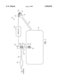
- FIG. 1 is a schematic view showing the on-board refueling vapor recovery system in accordance with the principles of the present invention.
- the present invention relates to an on-board refueling vapor recovery system for a motor vehicle, generally indicated at 10.
- the system includes a fuel tank 12, and a fuel fill pipe 14 which enables fluid communication between the fuel tank 12 and a fuel nozzle receiving portion or filler neck 16 defining a nozzle-receiving opening 18 for receiving a fuel nozzle which supplies liquid fuel to the fuel tank 12.
- a gas cap or filler neck closure structure, generally indicated at 20, is of any known construction and is constructed and arranged to be moved into closing engagement with the nozzle-receiving portion 16 to thereby seal the opening 18 from the external environment.
- a closure structure sensing device 22 is mounted with respect to the filler pipe 14 and/or the nozzle receiving portion 16 and is constructed and arranged to detect whether the closure structure 20 has been moved out of engagement with the nozzle-receiving portion 16, or whether it is secured in closing engagement with the nozzle-receiving portion 16. Sensing devices of this type are known in the art. It is contemplated that the closure structure sensing device 22 may function electrically, electromechanically or pneumatically in detecting whether the closure assembly 20 is in place.
- the closure structure sensing device 22 sends an electric signal to a control unit 24, which is preferably a microprocessor unit.
- control unit 24 In addition to receiving the signal from sensor 22, control unit 24 also receives a signal, for example, directly from the ignition, for detecting whether the ignition has been activated to indicate whether the engine of the vehicle is running.
- control unit 24 determines that the ignition has been activated, and, at the same time, that the closure structure 20 is not in closing engagement with the nozzle-receiving portion 16, the control unit 24 sends a warning indication, for example, in the form of an indication light on the motor vehicle dashboard for alerting the motor vehicle user. The vehicle user may then take the appropriate remedial action, such as replacing a lost closure structure 20.
- control unit 24 determines that the ignition is off and also that the closure structure 20 has been removed, the control unit 24 sends an electric signal to a valve actuating device 26.
- the actuating device 26 may be of any conventional type, preferably electromechanical, solenoid, motor operable, or electropneumatic.
- valve actuating device 26 Upon receiving the appropriate signal from the control unit 24, the valve actuating device 26 switches an on-board refueling vapor recovery exhaust valve structure, generally indicated at 28, from a closed to an opened condition.
- the valve structure 28 includes a movable sealing element 29, disposed in a normally closed position within the valve housing 31, for example, by operation of a coil spring 30.
- the actuating device 26 operates to move the movable valve element 29 against the bias of the spring 30 to open the valve structure 28. It should be appreciated that this described valve structure 28 is merely exemplary of the many various types of valves that can be used for this application which are widely known in the art.
- a vapor fume piping system generally indicated at 32, includes a first pipe 34 which extends into the fuel tank 12 and communicates between the tank 12 and the valve structure 28. Disposed at the end 36 of the first pipe 34 is a float valve 38, which is normally opened to permit fumes to pass thereby from the tank 12 to the valve structure 28.
- the float valve 38 includes a float member 40 which will be raised once the fuel level becomes sufficiently high to seal the end 36 of pipe 34. The float valve 38 will prevent overfilling in a conventional manner.
- the piping system 32 further includes a second pipe 36 which is in communication with the first pipe 34 through the valve structure 28 when it is in an opened condition (i.e., during a filling operating).
- the second pipe 36 extends from the valve structure 28 to a filtration device in the form of a carbon canister 44 containing a conventional carbon filter.
- the carbon canister 44 substantially removes the environmentally harmful components from the fuel vapors received from the second pipe 36, so that the exhaust to atmosphere is environmentally friendly.
- the carbon canister 44 will not be exposed to the fuel vapors while the vehicle is in operation or when the closure structure 20 is in closing engagement with the nozzle-receiving portion 16. As a result, the carbon filter material in canister 44 is preserved, and in particular, prevented from becoming unnecessarily and unduly saturated when its function is not required.
- the control unit 24 detects that the ignition is off and the closure structure 20 has been removed, and thereby sends a signal to the actuating device 26 which switches the valve structure 28 to an opened condition.
- Refueling through the fill pipe 14 into tank 12 will permit fuel vapors to vent through first pipe 34, valve structure 28, second pipe 36, and carbon canister 44 before being exhausted to the atmosphere.
- the closure structure 20 is replaced, and the closure structure sensing device 22 sends a signal (e.g., high or low signal) to control unit 24, which in turn sends a signal (e.g., high or low signal) to actuating device 26 to switch the valve structure 28 to a closed condition.
- the present invention advantageously utilizes a closure structure sensing device 22, which is conventionally known for sending a signal to the vehicle operator indicating that the closure structure 20 is not properly in place when driving.
- a closure structure sensing device 22 which is conventionally known for sending a signal to the vehicle operator indicating that the closure structure 20 is not properly in place when driving.
- the present invention obviates any need for mechanical valving in a filler pipe or nozzle receiving portion to control the path to the carbon canister 44.
- the present invention obviates the need for separate piping from the tank 12 to the nozzle receiving portion 16 and then back to the carbon canister 44.
Landscapes
- Engineering & Computer Science (AREA)
- Life Sciences & Earth Sciences (AREA)
- Sustainable Development (AREA)
- Sustainable Energy (AREA)
- Chemical & Material Sciences (AREA)
- Combustion & Propulsion (AREA)
- Transportation (AREA)
- Mechanical Engineering (AREA)
- Cooling, Air Intake And Gas Exhaust, And Fuel Tank Arrangements In Propulsion Units (AREA)
Priority Applications (1)
| Application Number | Priority Date | Filing Date | Title |
|---|---|---|---|
| US09/070,000 US5944076A (en) | 1997-04-30 | 1998-04-30 | On-board refueling vapor recovery system |
Applications Claiming Priority (2)
| Application Number | Priority Date | Filing Date | Title |
|---|---|---|---|
| US4443597P | 1997-04-30 | 1997-04-30 | |
| US09/070,000 US5944076A (en) | 1997-04-30 | 1998-04-30 | On-board refueling vapor recovery system |
Publications (1)
| Publication Number | Publication Date |
|---|---|
| US5944076A true US5944076A (en) | 1999-08-31 |
Family
ID=21932374
Family Applications (1)
| Application Number | Title | Priority Date | Filing Date |
|---|---|---|---|
| US09/070,000 Expired - Lifetime US5944076A (en) | 1997-04-30 | 1998-04-30 | On-board refueling vapor recovery system |
Country Status (2)
| Country | Link |
|---|---|
| US (1) | US5944076A (fr) |
| CA (1) | CA2236220C (fr) |
Cited By (18)
| Publication number | Priority date | Publication date | Assignee | Title |
|---|---|---|---|---|
| US6347723B1 (en) * | 1997-09-22 | 2002-02-19 | Bartec Componenten Und Systeme Gmbh | Method and security system for securing a flowable good |
| US6681811B2 (en) * | 2001-05-17 | 2004-01-27 | Ford Global Technologies, Llc | Fuel and reductant delivery system |
| EP1155896A3 (fr) * | 2000-05-19 | 2005-11-09 | Bayerische Motoren Werke Aktiengesellschaft | Système de contrôle et de commande pour un système de réservoir de carburant d'une automobile |
| US20060225709A1 (en) * | 2002-05-29 | 2006-10-12 | John Washeleski | Vehicle fuel management system |
| US20070175418A1 (en) * | 2006-01-31 | 2007-08-02 | Nissan Technical Center North America, Inc. | Vehicle reservoir tank |
| US20080105329A1 (en) * | 2006-11-03 | 2008-05-08 | Eaton Corporation | Electrically controlled refueling vapor vent shutoff |
| DE102007001545A1 (de) * | 2007-01-10 | 2008-07-17 | Bayerische Motoren Werke Aktiengesellschaft | Verfahren zum Befüllen eines Kraftstofftanks eines Kraftfahrzeugs sowie System zur Durchführung dieses Verfahrens |
| EP1956207A1 (fr) * | 2007-02-12 | 2008-08-13 | Iveco France S.A. | Réservoir d'urée pour véhicule de transport, unité comprenant un réservoir diesel et ledit réservoir d'urée |
| US7431021B1 (en) | 2007-09-19 | 2008-10-07 | Federal - Mogul World Wide, Inc. | Fuel vapor separator |
| US20080278300A1 (en) * | 2007-05-08 | 2008-11-13 | Honda Motor Co., Ltd. | System and method for verifying fuel cap engagement |
| US20100224284A1 (en) * | 2009-03-06 | 2010-09-09 | Kautex Textron Gmbh & Co. Kg | Reducing agent tank |
| WO2015118595A1 (fr) * | 2014-02-04 | 2015-08-13 | Toyota Jidosha Kabushiki Kaisha | Véhicule hybride et procédé de commande associé |
| US20180087475A1 (en) * | 2014-09-24 | 2018-03-29 | Eaton Corporation | Electrically controlled fuel system module |
| US20180272861A1 (en) * | 2017-03-22 | 2018-09-27 | Denso Corporation | Fuel tank system |
| US10954894B2 (en) | 2014-09-24 | 2021-03-23 | Eaton Intelligent Power Limited | Electrically controlled fuel system module |
| US11091027B2 (en) | 2016-06-09 | 2021-08-17 | Eaton Intelligent Power Limited | Electronic fuel tank system having cam actuated venting with canister line isolation |
| US20220205417A1 (en) * | 2019-07-01 | 2022-06-30 | Aisan Kogyo Kabushiki Kaisha | Evaporated fuel treatment apparatus |
| US11698045B2 (en) | 2014-09-24 | 2023-07-11 | Eaton Intelligent Power Limited | Electrically controlled fuel system module |
Citations (9)
| Publication number | Priority date | Publication date | Assignee | Title |
|---|---|---|---|---|
| US4747508A (en) * | 1987-03-09 | 1988-05-31 | General Motors Corporation | Fuel tank venting |
| US4821908A (en) * | 1987-09-03 | 1989-04-18 | General Motors Corporation | On-board refueling vapor recovery system |
| US4869283A (en) * | 1987-12-12 | 1989-09-26 | Daimler-Benz Aktiengesellschaft | Device for trapping fuel vapors during the refuelling of a fuel tank |
| US4924923A (en) * | 1989-05-17 | 1990-05-15 | Vernay Laboratories, Inc. | Fuel filler pipe seal |
| US5054528A (en) * | 1989-04-19 | 1991-10-08 | Fuji Jukogyo Kabushiki Kaisha | Venting device of a fuel tank for a motor vehicle |
| US5056494A (en) * | 1989-04-26 | 1991-10-15 | Toyota Jidosha Kabushiki Kaisha | System for treating vaporized fuel in an internal combustion engine |
| US5235955A (en) * | 1991-06-21 | 1993-08-17 | Kyosan Denki Kabushiki Kaisha | Fuel evaporative emission control system |
| US5404906A (en) * | 1992-12-21 | 1995-04-11 | Nissan Motor Co., Ltd. | Fuel tank |
| US5568828A (en) * | 1994-11-30 | 1996-10-29 | Stant Manufacturing Inc. | Fuel-delivery control system |
-
1998
- 1998-04-30 US US09/070,000 patent/US5944076A/en not_active Expired - Lifetime
- 1998-04-30 CA CA002236220A patent/CA2236220C/fr not_active Expired - Lifetime
Patent Citations (9)
| Publication number | Priority date | Publication date | Assignee | Title |
|---|---|---|---|---|
| US4747508A (en) * | 1987-03-09 | 1988-05-31 | General Motors Corporation | Fuel tank venting |
| US4821908A (en) * | 1987-09-03 | 1989-04-18 | General Motors Corporation | On-board refueling vapor recovery system |
| US4869283A (en) * | 1987-12-12 | 1989-09-26 | Daimler-Benz Aktiengesellschaft | Device for trapping fuel vapors during the refuelling of a fuel tank |
| US5054528A (en) * | 1989-04-19 | 1991-10-08 | Fuji Jukogyo Kabushiki Kaisha | Venting device of a fuel tank for a motor vehicle |
| US5056494A (en) * | 1989-04-26 | 1991-10-15 | Toyota Jidosha Kabushiki Kaisha | System for treating vaporized fuel in an internal combustion engine |
| US4924923A (en) * | 1989-05-17 | 1990-05-15 | Vernay Laboratories, Inc. | Fuel filler pipe seal |
| US5235955A (en) * | 1991-06-21 | 1993-08-17 | Kyosan Denki Kabushiki Kaisha | Fuel evaporative emission control system |
| US5404906A (en) * | 1992-12-21 | 1995-04-11 | Nissan Motor Co., Ltd. | Fuel tank |
| US5568828A (en) * | 1994-11-30 | 1996-10-29 | Stant Manufacturing Inc. | Fuel-delivery control system |
Cited By (28)
| Publication number | Priority date | Publication date | Assignee | Title |
|---|---|---|---|---|
| US6347723B1 (en) * | 1997-09-22 | 2002-02-19 | Bartec Componenten Und Systeme Gmbh | Method and security system for securing a flowable good |
| EP1155896A3 (fr) * | 2000-05-19 | 2005-11-09 | Bayerische Motoren Werke Aktiengesellschaft | Système de contrôle et de commande pour un système de réservoir de carburant d'une automobile |
| US6681811B2 (en) * | 2001-05-17 | 2004-01-27 | Ford Global Technologies, Llc | Fuel and reductant delivery system |
| US7377253B2 (en) * | 2002-05-29 | 2008-05-27 | Nartron Corporation | Vehicle fuel management system |
| US20060225709A1 (en) * | 2002-05-29 | 2006-10-12 | John Washeleski | Vehicle fuel management system |
| US7654410B2 (en) * | 2006-01-31 | 2010-02-02 | Nissan Technical Center North America, Inc. | Vehicle reservoir tank |
| US20070175418A1 (en) * | 2006-01-31 | 2007-08-02 | Nissan Technical Center North America, Inc. | Vehicle reservoir tank |
| US20080105329A1 (en) * | 2006-11-03 | 2008-05-08 | Eaton Corporation | Electrically controlled refueling vapor vent shutoff |
| US7866356B2 (en) * | 2006-11-03 | 2011-01-11 | Eaton Corporation | Electrically controlled refueling vapor vent shutoff |
| DE102007001545A1 (de) * | 2007-01-10 | 2008-07-17 | Bayerische Motoren Werke Aktiengesellschaft | Verfahren zum Befüllen eines Kraftstofftanks eines Kraftfahrzeugs sowie System zur Durchführung dieses Verfahrens |
| EP1956207A1 (fr) * | 2007-02-12 | 2008-08-13 | Iveco France S.A. | Réservoir d'urée pour véhicule de transport, unité comprenant un réservoir diesel et ledit réservoir d'urée |
| FR2912350A1 (fr) * | 2007-02-12 | 2008-08-15 | Iveco France Sa | Reservoir d'uree pour vehicule de transport, ensemble comprenant un reservoir de gasoil et un tel reservoir d'uree, vehicule de transport et organe de distribution correspondants |
| US20080278300A1 (en) * | 2007-05-08 | 2008-11-13 | Honda Motor Co., Ltd. | System and method for verifying fuel cap engagement |
| US7710250B2 (en) | 2007-05-08 | 2010-05-04 | Honda Motor Co., Ltd. | System and method for verifying fuel cap engagement |
| US7431021B1 (en) | 2007-09-19 | 2008-10-07 | Federal - Mogul World Wide, Inc. | Fuel vapor separator |
| EP2195521A4 (fr) * | 2007-09-19 | 2015-09-30 | Carter Fuel Systems Llc | Séparateur de vapeurs d'essence |
| US20100224284A1 (en) * | 2009-03-06 | 2010-09-09 | Kautex Textron Gmbh & Co. Kg | Reducing agent tank |
| CN102341575A (zh) * | 2009-03-06 | 2012-02-01 | 考特克斯·特克斯罗恩有限公司及两合公司 | 还原剂容器 |
| WO2010099908A1 (fr) * | 2009-03-06 | 2010-09-10 | Kautex Textron Gmbh & Co. Kg | Réservoir d'agent de réduction |
| WO2015118595A1 (fr) * | 2014-02-04 | 2015-08-13 | Toyota Jidosha Kabushiki Kaisha | Véhicule hybride et procédé de commande associé |
| US20180087475A1 (en) * | 2014-09-24 | 2018-03-29 | Eaton Corporation | Electrically controlled fuel system module |
| US10400713B2 (en) * | 2014-09-24 | 2019-09-03 | Eaton Corporation | Electrically controlled fuel system module |
| US10954894B2 (en) | 2014-09-24 | 2021-03-23 | Eaton Intelligent Power Limited | Electrically controlled fuel system module |
| US11698045B2 (en) | 2014-09-24 | 2023-07-11 | Eaton Intelligent Power Limited | Electrically controlled fuel system module |
| US11091027B2 (en) | 2016-06-09 | 2021-08-17 | Eaton Intelligent Power Limited | Electronic fuel tank system having cam actuated venting with canister line isolation |
| US20180272861A1 (en) * | 2017-03-22 | 2018-09-27 | Denso Corporation | Fuel tank system |
| US20220205417A1 (en) * | 2019-07-01 | 2022-06-30 | Aisan Kogyo Kabushiki Kaisha | Evaporated fuel treatment apparatus |
| US11852110B2 (en) * | 2019-07-01 | 2023-12-26 | Aisan Kogyo Kabushiki Kaisha | Evaporated fuel treatment apparatus |
Also Published As
| Publication number | Publication date |
|---|---|
| CA2236220C (fr) | 2007-01-02 |
| CA2236220A1 (fr) | 1998-10-30 |
Similar Documents
| Publication | Publication Date | Title |
|---|---|---|
| US5944076A (en) | On-board refueling vapor recovery system | |
| US7347191B2 (en) | Vehicle fuel system | |
| US7296600B2 (en) | Valve assembly and refueling sensor | |
| US5460135A (en) | Liquid fuel storage device | |
| US6516835B2 (en) | Electromechanically controlled refueling valve | |
| US6601617B2 (en) | Electromechanical refueling control system | |
| US5267470A (en) | Pressure sensor mounting for canister purge system | |
| US6213100B1 (en) | Multi-function fuel pump module | |
| US20090314072A1 (en) | Method and system for detecting a cap off situation on the fuel tank of a vehicle | |
| US7908099B2 (en) | Leak detection method and associated valve and fuel system | |
| US6311548B1 (en) | Method of validating a diagnostic leak detection test for a fuel tank | |
| US4819607A (en) | Vapor vent valve apparatus | |
| US6276193B1 (en) | Detecting vapor leakage in a motor vehicle fuel system | |
| US5450833A (en) | Breather for an internal combustion engine fuel tank | |
| BR112018006391A2 (en) | solenoid assembly for one valve | |
| US5960839A (en) | Fuel tank system | |
| JP5193352B2 (ja) | 自動車用燃料タンク | |
| US5361743A (en) | Breather for an internal combustion engine fuel tank | |
| JP2005104394A (ja) | 蒸発燃料排出抑制装置 | |
| EP1946954A1 (fr) | Procédé et système de détection de l'absence de bouchon sur le réservoir de carburant d'un véhicule | |
| GB2286182A (en) | A fuel tank venting arrangement for a motor vehicle | |
| US20050235968A1 (en) | Fuel vapor recovery system | |
| JP3531300B2 (ja) | 燃料蒸気排出制御装置 | |
| JP2024063449A (ja) | 密閉式燃料タンクシステム | |
| JPH058641A (ja) | 燃料タンクのバルブ配置構造 |
Legal Events
| Date | Code | Title | Description |
|---|---|---|---|
| AS | Assignment |
Owner name: BLAU INTERNATIONAL, GES.M.B.H., AUSTRIA Free format text: ASSIGNMENT OF ASSIGNORS INTEREST;ASSIGNOR:PALVOELGYI, SANDOR;REEL/FRAME:009990/0295 Effective date: 19970901 |
|
| STCF | Information on status: patent grant |
Free format text: PATENTED CASE |
|
| FPAY | Fee payment |
Year of fee payment: 4 |
|
| FPAY | Fee payment |
Year of fee payment: 8 |
|
| FPAY | Fee payment |
Year of fee payment: 12 |