US5946637A - Base station with detachable charger for cordless phone systems - Google Patents
Base station with detachable charger for cordless phone systems Download PDFInfo
- Publication number
- US5946637A US5946637A US08/896,299 US89629997A US5946637A US 5946637 A US5946637 A US 5946637A US 89629997 A US89629997 A US 89629997A US 5946637 A US5946637 A US 5946637A
- Authority
- US
- United States
- Prior art keywords
- charging station
- base station
- station
- charging
- connecting device
- Prior art date
- Legal status (The legal status is an assumption and is not a legal conclusion. Google has not performed a legal analysis and makes no representation as to the accuracy of the status listed.)
- Expired - Fee Related
Links
Images


Classifications
-
- H—ELECTRICITY
- H02—GENERATION; CONVERSION OR DISTRIBUTION OF ELECTRIC POWER
- H02J—ELECTRIC POWER NETWORKS; CIRCUIT ARRANGEMENTS OR SYSTEMS FOR SUPPLYING OR DISTRIBUTING ELECTRIC POWER; SYSTEMS FOR STORING ELECTRIC ENERGY
- H02J7/00—Circuit arrangements for charging or discharging batteries or for supplying loads from batteries
- H02J7/70—Circuit arrangements for charging or discharging batteries or for supplying loads from batteries characterised by the mechanical construction
- H02J7/751—Circuit arrangements for charging or discharging batteries or for supplying loads from batteries characterised by the mechanical construction concerning the insertion or the connection of the batteries
-
- H—ELECTRICITY
- H01—ELECTRIC ELEMENTS
- H01M—PROCESSES OR MEANS, e.g. BATTERIES, FOR THE DIRECT CONVERSION OF CHEMICAL ENERGY INTO ELECTRICAL ENERGY
- H01M50/00—Constructional details or processes of manufacture of the non-active parts of electrochemical cells other than fuel cells, e.g. hybrid cells
- H01M50/20—Mountings; Secondary casings or frames; Racks, modules or packs; Suspension devices; Shock absorbers; Transport or carrying devices; Holders
- H01M50/204—Racks, modules or packs for multiple batteries or multiple cells
- H01M50/207—Racks, modules or packs for multiple batteries or multiple cells characterised by their shape
- H01M50/213—Racks, modules or packs for multiple batteries or multiple cells characterised by their shape adapted for cells having curved cross-section, e.g. round or elliptic
-
- H—ELECTRICITY
- H04—ELECTRIC COMMUNICATION TECHNIQUE
- H04M—TELEPHONIC COMMUNICATION
- H04M19/00—Current supply arrangements for telephone systems
- H04M19/08—Current supply arrangements for telephone systems with current supply sources at the substations
-
- Y—GENERAL TAGGING OF NEW TECHNOLOGICAL DEVELOPMENTS; GENERAL TAGGING OF CROSS-SECTIONAL TECHNOLOGIES SPANNING OVER SEVERAL SECTIONS OF THE IPC; TECHNICAL SUBJECTS COVERED BY FORMER USPC CROSS-REFERENCE ART COLLECTIONS [XRACs] AND DIGESTS
- Y02—TECHNOLOGIES OR APPLICATIONS FOR MITIGATION OR ADAPTATION AGAINST CLIMATE CHANGE
- Y02E—REDUCTION OF GREENHOUSE GAS [GHG] EMISSIONS, RELATED TO ENERGY GENERATION, TRANSMISSION OR DISTRIBUTION
- Y02E60/00—Enabling technologies; Technologies with a potential or indirect contribution to GHG emissions mitigation
- Y02E60/10—Energy storage using batteries
Definitions
- the invention relates to a device for cordless telephones according to the preamble of Patent claim 1.
- Cordless telephones usually interact with a base station to which they are connected via a radio link.
- the base station is usually located in private households, office buildings or factory buildings etc. and permits cordless telephones which are associated with the same base station to communicate with one another, or with other subscribers via a private or public telephone network.
- the base station can be connected to these telephone networks via a data line or via a further radio link.
- Power is supplied to the base station generally via a feeder line from a power supply which is located in situ and may be, for example, in the form of a power supply unit.
- the cordless telephones themselves contain in their interior a battery which has to be recharged from time to time.
- charging stations which are separate from the base station. These charging stations are connected via a feeder line to a power source which is located in skit, for example to a power supply unit, and they contain in their interior a charging circuit for charging the battery of a cordless telephone when it has been inserted into a corresponding receptacle in the charging station.
- base stations which have an integrated charging station are already known.
- the charging station is supplied with power via the base station.
- the invention is based on the object of achieving, in the case of a device of the type mentioned at the beginning, a higher degree of flexibility with regard to the place of use of the charging station.
- An inventive device for cordless telephones with which a base station and at least one charging station are associated, in order to charge a battery of a cordless telephone via the charging station when the said cordless telephone is located in the charging station, is characterized by a mechanical connecting device for detachably connecting the charging station and base station to one another.
- the base station and charging station can thus be easily and quickly combined by fitting them together, or separated again from one another, as required, so that the entire device can be used in a more flexible way.
- the inventive device has the advantage that, for the case of charging the cordless telephone at a location which is remote from the base station, no further charging station is necessary since the charging station can be removed from the base station and carried along. For such an application, the costs of the entire system would be reduced.
- the advantage is obtained that one of these charging stations can be permanently connected to the base station in order to ensure that it is always possible for the cordless telephones to be charged, even at the location of the base station.
- the charging station can be fitted onto a top surface of the base station. This permits space-saving installation of the device which is composed of a base station and charging station.
- the mechanical connecting device is located in the region of the top surface of the base station and can therefore be easily found and activated.
- the mechanical connecting device may also be arranged here, for example centrally in this surface, thus avoiding the device becoming wider as a result of the mechanical connecting device.
- the mechanical connecting device is constructed as a latching or snap-on mechanism.
- the base station and charging station can be connected to one another, and separated from one another again, very easily without a special tool being necessary for this.
- positioning means are provided in order to position the charging station in relation to the base station when both are connected to one another. If the charging station does not assume the prescribed position in relation to the base station, the positioning means prevent the charging station from becoming closer to the base station, even as one is being fitted onto the other, so that a mechanical connection is not formed. This connection comes about only when the two stations are aligned correctly in relation to one another, with the result that incorrect positioning of the charging station is avoided.
- parts of the mechanical connecting device may also serve as positioning means, giving rise to a more compact design.
- the mechanical connecting device can preferably take the form of a plug-in connection, if said device is present between the top surface of the base station and the bottom surface of the charging station.
- a plug-forming projection may protrude from one of these surfaces and a bush-forming opening may be present in the other surface.
- an electric connecting device for electrically connecting the charging station and base station to one another in order to supply the charging station with power via the base station when both are connected mechanically to one another.
- the charging station no longer needs to remain connected to its original feeder line, which makes the unit composed of a base station and charging station easier to install.
- the electric connecting device may be arranged here in the region of the top surface of the base station, with the result that the mechanical and electric connections can be produced simultaneously when the charging station is fitted onto the top surface of the base station.
- the electric connecting device may be constructed as a plug/bush connection, which considerably simplifies the procedure of fitting the charging station onto the base station.
- the electric connecting device is integrated into the mechanical connecting device.
- the mechanical connecting device may also be constructed, at least to a certain degree, as an electric connecting device.
- latching means these may be composed of metal, for example, with the result that, on the one hand, they achieve the mechanical latching effect and, on the other hand, are able to produce an electric connection between the base station and charging station.
- the charging station contains not only a charging circuit but also a battery.
- a mains connection for example in the open air, for a certain period.
- the charging station may contain a switch-over device for switching over the charging circuit in such a way that, when there is an external power supply, the said charging circuit can charge the batteries both of the cordless telephone and of the charging station, while, in the event of the external power supply being interrupted, the battery of the cordless telephone can be charged by the battery of the charging station.
- External power supply means that the charging station is connected either to the base station or to a separate feeder line.
- interruption of the external power supply means that the charging station has been removed from the base station or that the separate feeder line has been removed from the charging station.
- the switching-over device must be capable of detecting these states, for which purpose it interacts with a suitable mechanical or electric detector device.
- the battery of the charging station may also be located in a separate housing component which can be removed therefrom. Otherwise, it would continue to be possible to connect the charging station to the base station. The charging station could then have the separate housing component added to it if desired if this is considered necessary for specific reasons.
- each charging station may be constructed in such a way that it can simultaneously accommodate a plurality of cordless telephones and charge their batteries. This then takes place in parallel mode.
- the charging station could be equipped with two recesses, one located next to the other, for receiving one cordless telephone each.
- FIG. 1 shows a device composed of a base station and charging station, in a state in which the charging station has been removed from the base station;
- FIG. 2 shows a device composed of a base station and charging station, in a state in which the charging station has been fitted onto the base station;
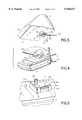
- FIG. 3 shows a perspective view of the charging station obliquely from below
- FIG. 4 shows a perspective view of the base station obliquely from above with a cover which can be fitted onto it;
- FIG. 5 shows an enlarged illustration of a mechanical and electric connecting device for connecting the base station and charging station to one another
- FIG. 6 shows a longitudinal section through the device which is composed of a base station and charging station and has a cordless telephone inserted into it;
- FIG. 7 shows a longitudinal section only through the charging station with a cordless telephone inserted into it
- FIG. 8 shows a longitudinal section through another embodiment of the charging station with a cordless telephone inserted into it.
- FIG. 9 shows a perspective view of the charging station from FIG. 7 or 8 with a cordless telephone inserted into it.
- FIG. 1 shows an inventive device 1, composed of a base station 2 and at least one charging station 3.
- the base station 2 and the charging station 3 are illustrated separated from one another.
- the base station 2 is connected via a radio link to one or more cordless telephones 4 or mobile phones, one of which is shown in FIG. 9.
- the base station 2 is provided with a swivellable antenna 5.
- the base station 2 is connected to a public or private telephone network via a data line 6.
- a plurality of cordless telephones 4 which are associated with the base station 2 can thus have radio contact with one another via the base station 2 or can be connected to another subscriber of the telephone network via the base station 2, and the data line 6 as well as the said telephone network.
- the base station 2 In order to supply power to the transmitting and receiving devices which are present (and not illustrated) within the base station 2, the base station 2 is connected to a feeder line 7 which is supplied via a power supply unit which is connected to the local power network. For example, a direct voltage of 6 V is applied to the feeder line 7.
- the base station 2 is provided with an upper receiving surface 8, which is constructed in the present case as a planar surface.
- the charging station 3 has a planar fitting surface 9 on its lower side.
- both surfaces 8 and 9 could even have curvatures. However, they would then have to be curved in the same way so that they can be fitted together.
- the mechanical connecting device is composed of a base 10 which protrudes beyond the receiving surface 8 and a recess 11, having approximately the same shape, in the lower fitting surface 9 of the charging station 3.
- the peripheral shapes of the base 10 and recess 11 are selected such that for the charging station 3 there is only one position in relation to the base station 2 in which it can be fitted onto the receiving surface 8 of the base station 2. Only in this position does the base 10 fit into the recess 11.
- the base 10 and the recess 11 are of trapezoidal construction, viewed parallel to the surfaces 8 and 9 in each case.
- the parallel sides of the trapezium lie perpendicular to the longitudinal direction of the handset 1.
- the obliquely running sides of the trapezium each run at an angle to this longitudinal direction.
- the said direction is indicated in FIG. 1 by the reference symbol L.
- the base 10 has in the region of its obliquely running trapezium sides 12 and 13 in each case a latching projection 14 of sprung construction, the said latching projection protruding outwards beyond these sides 12, 13 and being prestressed towards the outside by spring force.
- a latching projection 14 of sprung construction the said latching projection protruding outwards beyond these sides 12, 13 and being prestressed towards the outside by spring force.
- the obliquely running trapezium sides 15 and 16 of the recess 11 there are notches 17 for the said latching projections 14.
- FIG. 1 only the latching projection 14 on the trapezium side 12 of the base 10 can be seen.
- the latching projection on the trapezium side 13 is covered by the base 10.
- only the notch 17 on the trapezium side 16 can be seen.
- the latching projections 14 therefore engage in the respective notches 17 and thus constitute a secure connection between the base station 2 and the charging station 3. Then, owing to the selected shape of the mechanical connecting device 10, 11, it is no longer possible to turn the charging station 3 in relation to the base station 2.
- An additional protection against turning is obtained by way of a surface 18, at an angle with respect to the receiving surface 8, in the front region of the base station 2 against which a surface 19, at an angle with respect to the fitting surface 9, of the charging station 3 abuts when the surfaces 8 and 9 are fitted one on the other.
- An electric connecting device is integrated into the mechanical connecting device 10, 11.
- the said electrical connecting device is, on the one hand, a plug 20 which projects perpendicularly from the top surface of the base 10.
- This plug 20 is of two-pole construction and conducts a feed voltage as well as earth potential to the charging station 3.
- the charging station 3 is equipped in the region of its recess 11 with a corresponding sleeve, which cannot be seen in the present case and into which the plug 20 is inserted when the charging station 3 is fitted with its fitting surface 9 onto the receiving surface 8 of the base station 2.
- the inventive device 1 is shown in a state in which the charging station 3 is fitted onto the base station 2.
- supply potential and earth potential are also conducted to the charging station 3, and to the charging circuit which is present in the charging station 3, via the feeder line 7 and also via the electric connecting device 20.
- the charging station 3 does not have a cordless telephone fitted into it. Only one receptacle 21, provided for receiving a cordless telephone 4, can be seen in the charging station 3. If there is a cordless telephone 4 in this receptacle 21, the battery of the cordless telephone 4 is electrically connected to the charging circuit of the charging station 3 via a suitable contact device.
- FIG. 3 shows a perspective view of the charging station 3 from obliquely below.
- a plug 22 can also be inserted into this sleeve, the said plug 22 being connected to a further feeder line 23 in order, in this way, to transmit supply and earth potential to the charging circuit of the charging station 3.
- the further feeder line 23 can be connected to the local power supply, for example via a power supply unit.
- the charging station 3 can be fitted with its fitting surface 9 onto a suitable supporting surface, the further feeder line 23 is fed through a conduit 24 which is provided in the fitting surface 9 and which extends from the recess 11 to the rear side of the charging station 3.
- tongues 25 which run transversely with respect to the conduit are provided, the said tongues 25 being able to prevent the further feeder line 23 from dropping out of the conduit 24 and also being able to act as a tension relief.
- FIG. 4 shows the base station 2 without charging station 3. If the base station 2 is used in this state, a cover 26 can be fitted onto it in order to protect the mechanical and electric connecting device.
- This cover 26 is of identical construction in its lower region to the lower region of the charging station 3 and can thus be attached to the base station 2 by means of the latching projections 14.
- the said cover 26 can also only be fitted onto the receiving surface 8 in a specific position. In this way, the design of the base station 2 can be harmoniously supplemented in its upper region by the cover 26.
- FIG. 5 shows an enlarged portion of the base station 2 in the region of the base 10.
- the base 10 is, as already mentioned, of trapezoidal construction and protrudes beyond the receiving surface 8. Its top surface 10a lies parallel to the receiving surface 8, while its side surfaces lob, 10c which run perpendicularly to the longitudinal direction L, as well as its sides 12 and 13, run towards one another in the direction of the free end of the base.
- the entire base 10 thus tapers in the direction of its free end. The same applies, in the opposite direction, to the recess 11.
- the latching projections 14 are located at the top, or free, end of a respective catch 14a which, in the state of rest, is aligned with the side wall 12 and 13, so that then the latching projection 14 protrudes beyond the respective side wall 12, 13.
- the catch 14a can be coupled, for example to the receiving surface 8, or integrally connected thereto in a swivellable fashion, so that it can be pressed into a corresponding recess in the base 10 counter to a spring force. This goes so far that the tip of the latching projection 14 comes to rest in the respective side surface 12, 13.
- the latching projections 14 are pressed into the recess in the base 10 by the inner walls 15, 16 of the recess 11 when the base 10 is inserted therein.
- the latching projections 14 may be bevelled towards their free end.
- the catches 14a may be constructed as sprung catches or may be prestressed by means of a spring which comes to rest behind the respective catches 14a, that is to say between them and the base 10.
- FIG. 6 shows a longitudinal section through the inventive device, that is to say a section along the line L in FIG. 1.
- the charging station 3 is fitted onto the base station 2 and mechanically and electrically connected thereto.
- the base 10 engages in the recess 11, so that a secure connection is achieved between the base station 2 and charging station 3 by means of the latching projections 14.
- the plug 20 which protrudes out of the base 10 is inserted into the sleeve 27 of the charging station 3, so that there is also an electric connection between the power supply component of the base station 2 and the charging station 3.
- the plug 20 and sleeve 27 are each of two-pole design in order to be able to transmit feed potential and earth potential.
- the plug 20 is supported, inter alia, by a printed circuit board 28 which is located in the interior of the base station 2.
- This printed circuit board 28 is connected to a through-connecting element 29 which is attached to the rear wall of the base station 2 and serves to connect through the feeder line 7 into the interior of the base station 2.
- the electric connection between the feeder line 7 and plug 20 is made by suitable cable routing on the printed circuit board 28.
- a further printed circuit board 30 lies parallel to the bottom surface of the said charging station 3.
- the said printed circuit board 30 is attached there in a suitable way and has the already mentioned sleeve 27 for receiving the plug 20.
- On the printed circuit board 30 there is also a charging circuit 31 which is electrically connected to the sleeve 27 and serves to charge a cordless telephone 4 which is inserted into the already mentioned receptacle 21 of the base station 3.
- a connecting contact 32 which is connected to the further printed circuit board 30, is electrically connected, on the one hand, to the charging circuit 31 and, on the other hand, to a contact of the cordless telephone 4 which itself leads to the battery accommodated in the cordless telephone 4.
- the connecting contact 32 projects through a bottom opening 33 in the receptacle 21.
- FIG. 7 A longitudinal section, corresponding to FIG. 6, through the charging station 3 only is shown in FIG. 7. Identical elements to those in FIG. 6 are provided with the same reference symbols and are not described again.
- the plug 22 is inserted into the sleeve 27. Via this plug 22, connected to the further feeder line 23, feed potential and earth potential are likewise transmitted to the charging station 3, but now from a power supply unit (not illustrated) which may itself be connected to the local power supply.
- FIG. 8 shows a longitudinal section, corresponding to FIG. 7, through a further charging station 3 which corresponds externally to the charging station 3 according to FIG. 7. Identical components are in turn provided with the same reference symbols and are not described again.
- the charging station 3 In contrast with the charging station 3 according to FIG. 7, in the case of the charging station 3 according to FIG. 8 there is also a battery 34 on the further printed circuit board 30.
- a cordless telephone 4 which has been inserted into the charging station 3 can be charged in the previously described manner when the charging station 3 is not connected to an external power supply.
- the battery 34 is electrically connected to the charging circuit 3 in a suitable manner. If, on the other hand, the charging station 3 is connected to an external power supply, for example to the feeder line 23 via the plug 22 in accordance with FIG. 7, on the one hand, or to the feeder line 7 via the plug 20 in accordance with FIG.
- the charging circuit 31 can likewise contain a detector device by means of which it is determined whether or not the charging station 3 is connected to an external power supply, that is to say to one of the plugs 20 or 22. This detector circuit is provided with the reference symbol 35.
- a switch-over device 37 which serves to actuate or switch over the charging circuit 31 is electrically connected to the detector circuit 35. If the detector circuit 37 detects that the charging station 3 is being supplied with power externally, the switch-over device 37 switches the charging circuit 31 into a state in which the battery of the cordless telephone 4 and/or the battery 34 of the charging station 3 can be charged, depending on the priority assignment. If, on the other hand, the detector circuit 35 detects that there is no external power supply present for the charging station 3, the switch-over device 37 switches over the charging circuit 31 as a function of this result of the detector, in such a way that the battery of the cordless telephone 4 is now charged by the battery 34 of the charging station 3.
- the battery 34 may also be located in a separate housing component which can be removed from the charging station 3. This is no longer illustrated in detail.
- This housing component may be acquired additionally and added to the charging station 3 as desired when the extra function of charging the cordless telephone 4 by means of a battery 34 is desired.
- the connecting surface between the additional housing component and the rest of the charging station 3 can then come to rest in such a way that it lies parallel to the rear wall 36 of the receptacle 21. That wall of the charging station 3 which is at the rear when the additional housing component has been removed would then likewise lie parallel to the rear wall 36 of the receptacle 21, so that the charging station 3 could then be coupled on perpendicularly by means of its rear wall.
- the cordless telephone 4 When the cordless telephone 4 is located in the receptacle 21 it would then be in an approximately perpendicular position. In this case too, it could be ensured that it would still be possible to charge the battery of the cordless telephone 4 via the supply line 23 and the plug 22.
- FIG. 9 shows the charging station 3 with the cordless telephone 4 inserted into the receptacle 21, in a perspective view obliquely from the front.
- the charging station 3 could also be designed in such a way that it has two or more recesses 21 which are located one next to the other and into which in each case one of the cordless telephones 4 can be inserted in order to be charged.
- the charging procedure may take place in parallel.
- the receptacles 21 of differing designs in order to be able to accommodate and charge different makes of cordless telephones 4.
- the position of the connecting contacts 32 and the position of the associated openings 33 could be selected appropriately.
Landscapes
- Engineering & Computer Science (AREA)
- Power Engineering (AREA)
- Signal Processing (AREA)
- Chemical & Material Sciences (AREA)
- Chemical Kinetics & Catalysis (AREA)
- Electrochemistry (AREA)
- General Chemical & Material Sciences (AREA)
- Mobile Radio Communication Systems (AREA)
- Charge And Discharge Circuits For Batteries Or The Like (AREA)
- Telephone Set Structure (AREA)
Applications Claiming Priority (2)
| Application Number | Priority Date | Filing Date | Title |
|---|---|---|---|
| DE19620834 | 1996-05-23 | ||
| DE19620834A DE19620834C1 (de) | 1996-05-23 | 1996-05-23 | Einrichtung für Schnurlostelefone |
Publications (1)
| Publication Number | Publication Date |
|---|---|
| US5946637A true US5946637A (en) | 1999-08-31 |
Family
ID=7795155
Family Applications (1)
| Application Number | Title | Priority Date | Filing Date |
|---|---|---|---|
| US08/896,299 Expired - Fee Related US5946637A (en) | 1996-05-23 | 1997-05-16 | Base station with detachable charger for cordless phone systems |
Country Status (3)
| Country | Link |
|---|---|
| US (1) | US5946637A (fr) |
| EP (1) | EP0809386A3 (fr) |
| DE (1) | DE19620834C1 (fr) |
Cited By (43)
| Publication number | Priority date | Publication date | Assignee | Title |
|---|---|---|---|---|
| USD429212S (en) | 1999-01-05 | 2000-08-08 | Qualcomm Incorporated | Desk top charger for portable phone |
| USD431021S (en) * | 1999-08-04 | 2000-09-19 | Ericsson Inc. | Telephone holder and charger |
| USD433991S (en) * | 1999-10-07 | 2000-11-21 | Home Wireless Networks, Inc. | Desk-top charger base |
| USD434372S (en) * | 1999-10-07 | 2000-11-28 | Home Wireless Networks, Inc. | Desk-top/wall-mount charger base |
| US20010029195A1 (en) * | 2000-04-07 | 2001-10-11 | Chien-Min Lin | Recharge apparatus for holding the rechargeable device |
| US6375026B1 (en) | 1997-11-28 | 2002-04-23 | Nokia Mobile Phones Ltd. | Radiotelephone |
| USD460446S1 (en) | 2000-06-30 | 2002-07-16 | Vtech Communications, Ltd. | Auxiliary telephone base |
| USD461461S1 (en) | 2001-12-13 | 2002-08-13 | Tt Systems Llc | Cordless phone and base |
| USD468685S1 (en) | 1998-02-20 | 2003-01-14 | Qualcomm, Incorporated | Desk top battery charger for a portable phone |
| USD469075S1 (en) | 2000-06-20 | 2003-01-21 | Vtech Communications, Ltd. | Telephone handset and base |
| USD480393S1 (en) | 2002-08-15 | 2003-10-07 | Cisco Technology, Inc. | Handset cradle |
| USD501191S1 (en) * | 2003-08-20 | 2005-01-25 | Detewe Ag & Co. Kg | Docking station for telephones |
| USD501205S1 (en) * | 2004-03-22 | 2005-01-25 | Cko Designs, Inc. | Holder/charging stand for a mobile phone or the like |
| USD503700S1 (en) * | 2004-02-20 | 2005-04-05 | Detewe Ag & Co. | Docking station for telephones |
| US20050250449A1 (en) * | 2000-09-05 | 2005-11-10 | Simple Devices | Webpad and method for using the same |
| US20060031549A1 (en) * | 2000-09-05 | 2006-02-09 | Universal Electronics Inc. | System and method for using a webpad to control a data stream |
| US20060031550A1 (en) * | 2000-09-05 | 2006-02-09 | Universal Electronics Inc. | Webpad adapted to communicate using wide area and local area communication channels |
| USD516024S1 (en) | 2004-12-21 | 2006-02-28 | Ckq Design, Inc. | Holder/charging stand for a mobile phone or the like |
| USD516025S1 (en) | 2004-12-21 | 2006-02-28 | Ckq Designs, Inc. | Holder/charging stand for a mobile phone or the like |
| USD516023S1 (en) | 2004-12-21 | 2006-02-28 | Ckq Designs, Inc. | Holder/charging stand for a mobile phone or the like |
| US20060239445A1 (en) * | 1996-02-28 | 2006-10-26 | Thomas Fuhrmann | Radiotelephone |
| USD557693S1 (en) * | 2005-12-02 | 2007-12-18 | Samsung Electronics Co., Ltd. | Holder for portable phone |
| USD558749S1 (en) * | 2006-08-03 | 2008-01-01 | Matsushita Electric Industrial Co., Ltd. | Telephone base unit |
| USD561182S1 (en) * | 2007-05-29 | 2008-02-05 | Symbol Technologies, Inc. | Cradle for a mobile device |
| US20090160400A1 (en) * | 2007-12-21 | 2009-06-25 | Steven Woud | Case battery system |
| US20100039063A1 (en) * | 2005-02-08 | 2010-02-18 | Versalite Associates | Versatile lighting device |
| USD617303S1 (en) * | 2009-11-25 | 2010-06-08 | Panasonic Corporation | Telephone base unit |
| US20110001455A1 (en) * | 2005-02-08 | 2011-01-06 | Versalite Associates | Extended reach battery charging system |
| US20110028189A1 (en) * | 2009-02-20 | 2011-02-03 | Chu-Keng Lin | Charging Cradle |
| USD635118S1 (en) * | 2008-08-29 | 2011-03-29 | Panasonic Corporation | Telephone base unit |
| US20120104995A1 (en) * | 2010-10-28 | 2012-05-03 | Samsung Electronics Co. Ltd. | Charging device for mobile terminal |
| USD697474S1 (en) * | 2012-09-06 | 2014-01-14 | Costruzioni Elettroniche Industriali Automatismi S.P.A. C.E.I.A. S.P.A. | Battery charger |
| USD721649S1 (en) | 2014-01-02 | 2015-01-27 | Mophie, Inc. | Electrical charger and docking station |
| USD722056S1 (en) | 2013-01-08 | 2015-02-03 | Mophie, Inc. | Desktop mobile device dock |
| USD726175S1 (en) | 2013-01-08 | 2015-04-07 | Mophie, Inc. | Mobile device vehicle mount |
| US9274556B2 (en) | 2011-01-05 | 2016-03-01 | Mophie, Inc. | Tablet computer stand |
| USD859393S1 (en) | 2018-01-05 | 2019-09-10 | Mophie Inc. | Electronic device mount |
| US10536990B1 (en) * | 2009-02-03 | 2020-01-14 | Dominic M. Kotab | Telephone base station for combining mobile and terrestrial telephone service |
| US10541546B1 (en) | 2016-08-25 | 2020-01-21 | Versalite Associates, Llc | System and apparatus for providing power to remote electronic devices |
| USD873260S1 (en) | 2018-06-22 | 2020-01-21 | Mophie Inc. | Mount for electronic device |
| USD873272S1 (en) | 2018-06-22 | 2020-01-21 | Mophie Inc. | Mount for electronic device |
| US11014509B2 (en) | 2019-02-13 | 2021-05-25 | Mophie Inc. | Mount for holding a mobile electronic device |
| US11171449B2 (en) * | 2015-10-27 | 2021-11-09 | Nintendo Co., Ltd. | Charger and charging system |
Families Citing this family (3)
| Publication number | Priority date | Publication date | Assignee | Title |
|---|---|---|---|---|
| US6316911B1 (en) | 1997-08-08 | 2001-11-13 | Black & Decker Inc. | Battery and flashlight recharger |
| DE102010062820A1 (de) * | 2010-12-10 | 2012-06-14 | Siemens Aktiengesellschaft | Energieversorgungseinrichtung |
| DE102016104370A1 (de) * | 2016-03-10 | 2017-09-14 | Miele & Cie. Kg | Ladestation für einen Saugrobotor |
Citations (22)
| Publication number | Priority date | Publication date | Assignee | Title |
|---|---|---|---|---|
| US4634810A (en) * | 1984-01-05 | 1987-01-06 | Siemens Aktiengesellschaft | Station for the accommodation of a chargeable cordless telephone |
| US4882745A (en) * | 1987-05-08 | 1989-11-21 | Silver Alan H | Cordless headset telephone |
| US5073928A (en) * | 1989-04-18 | 1991-12-17 | Kabushiki Kaisha Toshiba | Cordless telephone system having an automatic answering device |
| US5136229A (en) * | 1991-07-15 | 1992-08-04 | Galvin Jay M | Power pack device |
| US5170494A (en) * | 1988-12-08 | 1992-12-08 | Nokia Mobile Phones Ltd. | Two piece radio telephone |
| US5208494A (en) * | 1989-03-10 | 1993-05-04 | Nokia Mobile Phones Ltd. | Method for the elimination of transients from the operating voltage of TDMA system |
| US5214309A (en) * | 1989-02-17 | 1993-05-25 | Nokia Mobile Phones Ltd. | Thermally conductive bar cooling arrangement for a transistor |
| US5229701A (en) * | 1990-04-12 | 1993-07-20 | Nokia Mobile Phones Ltd. | Battery charger for battery-operated equipment |
| US5253146A (en) * | 1990-12-13 | 1993-10-12 | Nokia Mobile Phones Ltd. | Earthed intermediate frame for circuit boards |
| US5265158A (en) * | 1989-05-25 | 1993-11-23 | Nokia Mobile Phones Ltd. | Construction of a stand alone portable telephone unit |
| US5271056A (en) * | 1990-04-12 | 1993-12-14 | Nokia Mobile Phones Ltd. | Electromagnetic interference shielding construction in a radio telephone |
| US5327482A (en) * | 1991-07-08 | 1994-07-05 | Kabushiki Kaisha Toshiba | Public cordless telephone system with coin/card insertion inhibiting means |
| US5343136A (en) * | 1989-01-31 | 1994-08-30 | Kabushiki Kaisha Toshiba | Charger for charging a rechargeable battery |
| US5511240A (en) * | 1991-11-05 | 1996-04-23 | Nec Corporation | Radio telephone system capable of transmitting data communication through a battery charger |
| US5519711A (en) * | 1993-11-22 | 1996-05-21 | Nokia Mobile Phones Ltd. | Switch-mode power supply for time division multiple access radio phone systems |
| US5584055A (en) * | 1991-01-11 | 1996-12-10 | Kabushiki Kaisha Toshiba | Adapter unit for adaptively supplying a portable radio telephone with power |
| US5603103A (en) * | 1993-11-26 | 1997-02-11 | Nokia Mobile Phones Ltd. | Radio telephone with compliant shield and method |
| JPH09149106A (ja) * | 1995-11-21 | 1997-06-06 | Matsushita Electric Ind Co Ltd | 無線電話装置 |
| US5691618A (en) * | 1992-11-16 | 1997-11-25 | Yupiteru Industries Co., Ltd. | Battery pack charging device |
| US5739665A (en) * | 1996-01-25 | 1998-04-14 | Enbloc, Inc. | Radio modem docking station for palm-sized computer |
| US5801513A (en) * | 1996-12-31 | 1998-09-01 | Motorola, Inc. | Apparatus for charging batteries and supplying backup power |
| US5828966A (en) * | 1996-05-23 | 1998-10-27 | Davis; Russell | Universal charging cradle for cordless telephones |
Family Cites Families (5)
| Publication number | Priority date | Publication date | Assignee | Title |
|---|---|---|---|---|
| DE3736608C1 (de) * | 1987-10-29 | 1988-10-06 | Telefonbau & Normalzeit Gmbh | Ladestation fuer ein schnurloses Telefon |
| JPH043640A (ja) * | 1990-04-20 | 1992-01-08 | Tokyo Electric Co Ltd | コードレス電話機 |
| US5010565A (en) * | 1990-06-29 | 1991-04-23 | Bryan Nash | Apparatus and method for adding cordless handset capability to an existing corded telephone |
| JPH04196851A (ja) * | 1990-11-28 | 1992-07-16 | Iwatsu Electric Co Ltd | コードレス電話装置 |
| SE518649C2 (sv) * | 1993-06-22 | 2002-11-05 | Ericsson Telefon Ab L M | Förfarande för telekommunikationsaccess i en multinätmiljö |
-
1996
- 1996-05-23 DE DE19620834A patent/DE19620834C1/de not_active Expired - Fee Related
-
1997
- 1997-04-23 EP EP97106738A patent/EP0809386A3/fr not_active Withdrawn
- 1997-05-16 US US08/896,299 patent/US5946637A/en not_active Expired - Fee Related
Patent Citations (22)
| Publication number | Priority date | Publication date | Assignee | Title |
|---|---|---|---|---|
| US4634810A (en) * | 1984-01-05 | 1987-01-06 | Siemens Aktiengesellschaft | Station for the accommodation of a chargeable cordless telephone |
| US4882745A (en) * | 1987-05-08 | 1989-11-21 | Silver Alan H | Cordless headset telephone |
| US5170494A (en) * | 1988-12-08 | 1992-12-08 | Nokia Mobile Phones Ltd. | Two piece radio telephone |
| US5343136A (en) * | 1989-01-31 | 1994-08-30 | Kabushiki Kaisha Toshiba | Charger for charging a rechargeable battery |
| US5214309A (en) * | 1989-02-17 | 1993-05-25 | Nokia Mobile Phones Ltd. | Thermally conductive bar cooling arrangement for a transistor |
| US5208494A (en) * | 1989-03-10 | 1993-05-04 | Nokia Mobile Phones Ltd. | Method for the elimination of transients from the operating voltage of TDMA system |
| US5073928A (en) * | 1989-04-18 | 1991-12-17 | Kabushiki Kaisha Toshiba | Cordless telephone system having an automatic answering device |
| US5265158A (en) * | 1989-05-25 | 1993-11-23 | Nokia Mobile Phones Ltd. | Construction of a stand alone portable telephone unit |
| US5271056A (en) * | 1990-04-12 | 1993-12-14 | Nokia Mobile Phones Ltd. | Electromagnetic interference shielding construction in a radio telephone |
| US5229701A (en) * | 1990-04-12 | 1993-07-20 | Nokia Mobile Phones Ltd. | Battery charger for battery-operated equipment |
| US5253146A (en) * | 1990-12-13 | 1993-10-12 | Nokia Mobile Phones Ltd. | Earthed intermediate frame for circuit boards |
| US5584055A (en) * | 1991-01-11 | 1996-12-10 | Kabushiki Kaisha Toshiba | Adapter unit for adaptively supplying a portable radio telephone with power |
| US5327482A (en) * | 1991-07-08 | 1994-07-05 | Kabushiki Kaisha Toshiba | Public cordless telephone system with coin/card insertion inhibiting means |
| US5136229A (en) * | 1991-07-15 | 1992-08-04 | Galvin Jay M | Power pack device |
| US5511240A (en) * | 1991-11-05 | 1996-04-23 | Nec Corporation | Radio telephone system capable of transmitting data communication through a battery charger |
| US5691618A (en) * | 1992-11-16 | 1997-11-25 | Yupiteru Industries Co., Ltd. | Battery pack charging device |
| US5519711A (en) * | 1993-11-22 | 1996-05-21 | Nokia Mobile Phones Ltd. | Switch-mode power supply for time division multiple access radio phone systems |
| US5603103A (en) * | 1993-11-26 | 1997-02-11 | Nokia Mobile Phones Ltd. | Radio telephone with compliant shield and method |
| JPH09149106A (ja) * | 1995-11-21 | 1997-06-06 | Matsushita Electric Ind Co Ltd | 無線電話装置 |
| US5739665A (en) * | 1996-01-25 | 1998-04-14 | Enbloc, Inc. | Radio modem docking station for palm-sized computer |
| US5828966A (en) * | 1996-05-23 | 1998-10-27 | Davis; Russell | Universal charging cradle for cordless telephones |
| US5801513A (en) * | 1996-12-31 | 1998-09-01 | Motorola, Inc. | Apparatus for charging batteries and supplying backup power |
Cited By (60)
| Publication number | Priority date | Publication date | Assignee | Title |
|---|---|---|---|---|
| US20060239445A1 (en) * | 1996-02-28 | 2006-10-26 | Thomas Fuhrmann | Radiotelephone |
| US7885403B2 (en) | 1996-02-28 | 2011-02-08 | Nokia Corporation | Radiotelephone |
| US6375026B1 (en) | 1997-11-28 | 2002-04-23 | Nokia Mobile Phones Ltd. | Radiotelephone |
| USD468685S1 (en) | 1998-02-20 | 2003-01-14 | Qualcomm, Incorporated | Desk top battery charger for a portable phone |
| USD429212S (en) | 1999-01-05 | 2000-08-08 | Qualcomm Incorporated | Desk top charger for portable phone |
| USD431021S (en) * | 1999-08-04 | 2000-09-19 | Ericsson Inc. | Telephone holder and charger |
| USD433991S (en) * | 1999-10-07 | 2000-11-21 | Home Wireless Networks, Inc. | Desk-top charger base |
| USD434372S (en) * | 1999-10-07 | 2000-11-28 | Home Wireless Networks, Inc. | Desk-top/wall-mount charger base |
| US20010029195A1 (en) * | 2000-04-07 | 2001-10-11 | Chien-Min Lin | Recharge apparatus for holding the rechargeable device |
| US6816740B2 (en) * | 2000-04-07 | 2004-11-09 | High Tech Computer Corp. | Recharge apparatus for holding the rechargeable device |
| USD472538S1 (en) | 2000-06-20 | 2003-04-01 | Vtech Communications, Ltd. | Telephone base |
| USD469075S1 (en) | 2000-06-20 | 2003-01-21 | Vtech Communications, Ltd. | Telephone handset and base |
| USD460446S1 (en) | 2000-06-30 | 2002-07-16 | Vtech Communications, Ltd. | Auxiliary telephone base |
| US9628545B2 (en) | 2000-09-05 | 2017-04-18 | Callahan Cellular L.L.C. | System and method for using a webpad to control a data stream |
| US8078751B2 (en) | 2000-09-05 | 2011-12-13 | Viviana Research Llc | System and method for using a webpad to control a data stream |
| US20110145721A1 (en) * | 2000-09-05 | 2011-06-16 | Janik Craig M | System and method for using a webpad to control a data stream |
| US7904579B2 (en) | 2000-09-05 | 2011-03-08 | Viviana Research Llc | System and method for using a webpad to control a data stream |
| US20050250449A1 (en) * | 2000-09-05 | 2005-11-10 | Simple Devices | Webpad and method for using the same |
| US20060031549A1 (en) * | 2000-09-05 | 2006-02-09 | Universal Electronics Inc. | System and method for using a webpad to control a data stream |
| US20060031550A1 (en) * | 2000-09-05 | 2006-02-09 | Universal Electronics Inc. | Webpad adapted to communicate using wide area and local area communication channels |
| US7660601B2 (en) * | 2000-09-05 | 2010-02-09 | Janik Craig M | Webpad and method for using the same |
| USD461461S1 (en) | 2001-12-13 | 2002-08-13 | Tt Systems Llc | Cordless phone and base |
| USD480393S1 (en) | 2002-08-15 | 2003-10-07 | Cisco Technology, Inc. | Handset cradle |
| USD501191S1 (en) * | 2003-08-20 | 2005-01-25 | Detewe Ag & Co. Kg | Docking station for telephones |
| USD503700S1 (en) * | 2004-02-20 | 2005-04-05 | Detewe Ag & Co. | Docking station for telephones |
| USD501205S1 (en) * | 2004-03-22 | 2005-01-25 | Cko Designs, Inc. | Holder/charging stand for a mobile phone or the like |
| USD516025S1 (en) | 2004-12-21 | 2006-02-28 | Ckq Designs, Inc. | Holder/charging stand for a mobile phone or the like |
| USD516023S1 (en) | 2004-12-21 | 2006-02-28 | Ckq Designs, Inc. | Holder/charging stand for a mobile phone or the like |
| USD516024S1 (en) | 2004-12-21 | 2006-02-28 | Ckq Design, Inc. | Holder/charging stand for a mobile phone or the like |
| US20100039063A1 (en) * | 2005-02-08 | 2010-02-18 | Versalite Associates | Versatile lighting device |
| US8358101B2 (en) | 2005-02-08 | 2013-01-22 | Versalite Associates, Llc | Extended reach battery charging system |
| US20110001455A1 (en) * | 2005-02-08 | 2011-01-06 | Versalite Associates | Extended reach battery charging system |
| US7772801B2 (en) * | 2005-02-08 | 2010-08-10 | Versalite Associates | Versatile lighting device |
| USD557693S1 (en) * | 2005-12-02 | 2007-12-18 | Samsung Electronics Co., Ltd. | Holder for portable phone |
| USD558749S1 (en) * | 2006-08-03 | 2008-01-01 | Matsushita Electric Industrial Co., Ltd. | Telephone base unit |
| USD561182S1 (en) * | 2007-05-29 | 2008-02-05 | Symbol Technologies, Inc. | Cradle for a mobile device |
| US20090160400A1 (en) * | 2007-12-21 | 2009-06-25 | Steven Woud | Case battery system |
| US7859222B2 (en) * | 2007-12-21 | 2010-12-28 | Steven Woud | Case battery system |
| USD635118S1 (en) * | 2008-08-29 | 2011-03-29 | Panasonic Corporation | Telephone base unit |
| US10785612B2 (en) * | 2009-02-03 | 2020-09-22 | Dominic M. Kotab | Telephone base station for combining mobile and terrestrial telephone service |
| US10887732B2 (en) * | 2009-02-03 | 2021-01-05 | Dominic M. Kotab | Telephone base station for combining mobile and VOIP telephone service |
| US10681507B2 (en) * | 2009-02-03 | 2020-06-09 | Dominic M. Kotab | Telephone base station for combining mobile and terrestrial telephone service |
| US10555137B2 (en) * | 2009-02-03 | 2020-02-04 | Dominic M. Kotab | Telephone base station for combining mobile and terrestrial telephone service |
| US10536990B1 (en) * | 2009-02-03 | 2020-01-14 | Dominic M. Kotab | Telephone base station for combining mobile and terrestrial telephone service |
| US20110028189A1 (en) * | 2009-02-20 | 2011-02-03 | Chu-Keng Lin | Charging Cradle |
| US8165643B2 (en) * | 2009-02-20 | 2012-04-24 | Cheng Uei Precision Industry Co., Ltd. | Charging cradle |
| USD617303S1 (en) * | 2009-11-25 | 2010-06-08 | Panasonic Corporation | Telephone base unit |
| USD624898S1 (en) * | 2009-11-25 | 2010-10-05 | Panasonic Corporation | Telephone base unit |
| US20120104995A1 (en) * | 2010-10-28 | 2012-05-03 | Samsung Electronics Co. Ltd. | Charging device for mobile terminal |
| US9274556B2 (en) | 2011-01-05 | 2016-03-01 | Mophie, Inc. | Tablet computer stand |
| USD697474S1 (en) * | 2012-09-06 | 2014-01-14 | Costruzioni Elettroniche Industriali Automatismi S.P.A. C.E.I.A. S.P.A. | Battery charger |
| USD722056S1 (en) | 2013-01-08 | 2015-02-03 | Mophie, Inc. | Desktop mobile device dock |
| USD726175S1 (en) | 2013-01-08 | 2015-04-07 | Mophie, Inc. | Mobile device vehicle mount |
| USD721649S1 (en) | 2014-01-02 | 2015-01-27 | Mophie, Inc. | Electrical charger and docking station |
| US11171449B2 (en) * | 2015-10-27 | 2021-11-09 | Nintendo Co., Ltd. | Charger and charging system |
| US10541546B1 (en) | 2016-08-25 | 2020-01-21 | Versalite Associates, Llc | System and apparatus for providing power to remote electronic devices |
| USD859393S1 (en) | 2018-01-05 | 2019-09-10 | Mophie Inc. | Electronic device mount |
| USD873260S1 (en) | 2018-06-22 | 2020-01-21 | Mophie Inc. | Mount for electronic device |
| USD873272S1 (en) | 2018-06-22 | 2020-01-21 | Mophie Inc. | Mount for electronic device |
| US11014509B2 (en) | 2019-02-13 | 2021-05-25 | Mophie Inc. | Mount for holding a mobile electronic device |
Also Published As
| Publication number | Publication date |
|---|---|
| DE19620834C1 (de) | 1997-06-19 |
| EP0809386A2 (fr) | 1997-11-26 |
| EP0809386A3 (fr) | 2003-07-09 |
Similar Documents
| Publication | Publication Date | Title |
|---|---|---|
| US5946637A (en) | Base station with detachable charger for cordless phone systems | |
| US5535274A (en) | Universal connection for cellular telephone interface | |
| US6424842B1 (en) | Dual function connector for cellular phones | |
| EP0900700B1 (fr) | Système de distribution électrique | |
| US5732361A (en) | Adapter for mobile phone | |
| US5668698A (en) | Smart connector for an electrical device | |
| CA2302583A1 (fr) | Module de ligne d'abonne au telephone | |
| WO1992000641A1 (fr) | Appareil et procede servant a ajouter une possibilite de combine sans fil a un telephone a fil existant | |
| KR100544246B1 (ko) | 전기 커넥터 및 전기 커넥터 조립체 | |
| WO1998039942A1 (fr) | Fixation de microphone pour la connexion electrique de ce dernier et d'un circuit audio a un radiotelephone a volet, dote d'un dispositif de contact mecanique | |
| EP0961466A1 (fr) | Unité d'alimentation et de recharge d'énergie pour des téléphones portables en particulier des téléphones cellulaires | |
| KR19990037388A (ko) | 축적 장치를 포함하는 전화통신 장치 및 이와 같은 전화통신 장치에 적합한 축적 장치 | |
| CA1237211A (fr) | Combine telephonique a membre se pretant a l'insertion en sens inverse | |
| JP2000349875A (ja) | 無線通信機および電池パックおよびコネクタ | |
| KR100576008B1 (ko) | 휴대용 단말기의 메인 보드 | |
| KR20000011481A (ko) | 휴대가능한전자장치,그의하우징,및그의배터리칸막이 | |
| GB2377825A (en) | Device with expansion adaprot slotted into battery | |
| EP0961465A1 (fr) | Système de connexion de téléphones cellulaires à un système téléphonique résidentiel | |
| KR100733492B1 (ko) | 스위치가 부설된 콘센트 | |
| US6044280A (en) | Arrangement in which a useful signal is transmitted between at least two device units | |
| GB2314483A (en) | Mobile phone with additional plug-in communication module | |
| US7539522B2 (en) | Cordless wall phone with voltage outlet separation | |
| HK1026546A (en) | System for connecting cellular telephones to a home telephone system | |
| JP2523881Y2 (ja) | 携帯通信機器 | |
| MXPA97005487A (en) | Conforming system of case for cellular, compact and portable telephone, and connect |
Legal Events
| Date | Code | Title | Description |
|---|---|---|---|
| AS | Assignment |
Owner name: NOKIA MOBILE PHONES LIMITED, FINLAND Free format text: ASSIGNMENT OF ASSIGNORS INTEREST;ASSIGNORS:UMBACH, DIRK;MICHALZIK, DIRK;WEBER, RAINER;REEL/FRAME:008979/0672 Effective date: 19970516 |
|
| FPAY | Fee payment |
Year of fee payment: 4 |
|
| FEPP | Fee payment procedure |
Free format text: PAYOR NUMBER ASSIGNED (ORIGINAL EVENT CODE: ASPN); ENTITY STATUS OF PATENT OWNER: LARGE ENTITY |
|
| FPAY | Fee payment |
Year of fee payment: 8 |
|
| FEPP | Fee payment procedure |
Free format text: PAYER NUMBER DE-ASSIGNED (ORIGINAL EVENT CODE: RMPN); ENTITY STATUS OF PATENT OWNER: LARGE ENTITY Free format text: PAYOR NUMBER ASSIGNED (ORIGINAL EVENT CODE: ASPN); ENTITY STATUS OF PATENT OWNER: LARGE ENTITY |
|
| REMI | Maintenance fee reminder mailed | ||
| LAPS | Lapse for failure to pay maintenance fees | ||
| STCH | Information on status: patent discontinuation |
Free format text: PATENT EXPIRED DUE TO NONPAYMENT OF MAINTENANCE FEES UNDER 37 CFR 1.362 |
|
| FP | Lapsed due to failure to pay maintenance fee |
Effective date: 20110831 |