US5970720A - Combined refrigerators and detecting system using the same - Google Patents
Combined refrigerators and detecting system using the same Download PDFInfo
- Publication number
- US5970720A US5970720A US08/501,533 US50153395A US5970720A US 5970720 A US5970720 A US 5970720A US 50153395 A US50153395 A US 50153395A US 5970720 A US5970720 A US 5970720A
- Authority
- US
- United States
- Prior art keywords
- detector
- detecting system
- cylinders
- cooling
- radiation detector
- Prior art date
- Legal status (The legal status is an assumption and is not a legal conclusion. Google has not performed a legal analysis and makes no representation as to the accuracy of the status listed.)
- Expired - Fee Related
Links
Images


Classifications
-
- G—PHYSICS
- G01—MEASURING; TESTING
- G01V—GEOPHYSICS; GRAVITATIONAL MEASUREMENTS; DETECTING MASSES OR OBJECTS; TAGS
- G01V8/00—Prospecting or detecting by optical means
- G01V8/10—Detecting, e.g. by using light barriers
-
- F—MECHANICAL ENGINEERING; LIGHTING; HEATING; WEAPONS; BLASTING
- F25—REFRIGERATION OR COOLING; COMBINED HEATING AND REFRIGERATION SYSTEMS; HEAT PUMP SYSTEMS; MANUFACTURE OR STORAGE OF ICE; LIQUEFACTION SOLIDIFICATION OF GASES
- F25B—REFRIGERATION MACHINES, PLANTS OR SYSTEMS; COMBINED HEATING AND REFRIGERATION SYSTEMS; HEAT PUMP SYSTEMS
- F25B9/00—Compression machines, plants or systems, in which the refrigerant is air or other gas of low boiling point
- F25B9/14—Compression machines, plants or systems, in which the refrigerant is air or other gas of low boiling point characterised by the cycle used, e.g. Stirling cycle
-
- F—MECHANICAL ENGINEERING; LIGHTING; HEATING; WEAPONS; BLASTING
- F25—REFRIGERATION OR COOLING; COMBINED HEATING AND REFRIGERATION SYSTEMS; HEAT PUMP SYSTEMS; MANUFACTURE OR STORAGE OF ICE; LIQUEFACTION SOLIDIFICATION OF GASES
- F25B—REFRIGERATION MACHINES, PLANTS OR SYSTEMS; COMBINED HEATING AND REFRIGERATION SYSTEMS; HEAT PUMP SYSTEMS
- F25B2309/00—Gas cycle refrigeration machines
- F25B2309/001—Gas cycle refrigeration machines with a linear configuration or a linear motor
-
- F—MECHANICAL ENGINEERING; LIGHTING; HEATING; WEAPONS; BLASTING
- F25—REFRIGERATION OR COOLING; COMBINED HEATING AND REFRIGERATION SYSTEMS; HEAT PUMP SYSTEMS; MANUFACTURE OR STORAGE OF ICE; LIQUEFACTION SOLIDIFICATION OF GASES
- F25B—REFRIGERATION MACHINES, PLANTS OR SYSTEMS; COMBINED HEATING AND REFRIGERATION SYSTEMS; HEAT PUMP SYSTEMS
- F25B2500/00—Problems to be solved
- F25B2500/13—Vibrations
Definitions
- the present invention relates to a refrigerator, and more particularly to a refrigerator for cooling a detector by using electricity and a detecting system using the refrigerator.
- a semiconductor radiation detecting system detects radiation while cooling a semiconductor radiation detector. This system is widely used not only for measuring radiation such as gamma rays and X-rays at nuclear reactor facilities but also in other radiation measurement fields such as nuclear physics, astro-physics, and nuclear chemistry.
- FIG. 17 shows a semiconductor radiation detecting system of a liquid nitrogen cooling type heretofore used.
- Liquid nitrogen 103 is filled in a double-walled cooling vessel 102.
- a cooling rod 104 extends from the inner side wall of the cooling vessel 102 through a pipe 108 and the flange 107 mounted on the outer side wall of the vessel 102.
- a semiconductor radiation detector 101 is mounted on the front end of the cooling rod 104.
- a vacuum vessel 105 is hermetically mounted on the flange 107.
- the cooling rod 104 and semiconductor radiation detector 101 are hermetically housed in the vacuum vessel 105.
- the semiconductor radiation detector 101 is cooled with the cooling rod 104 to a temperature near a liquid nitrogen temperature.
- a preamplifier 106 is placed on the side wall of the pipe 108.
- a radiation detection signal outputted from the semiconductor radiation detector 101 is supplied via lead wires (not shown) to the preamplifier 106 which amplifies the inputted radiation detection signal and supplies it to a radiation signal processing (acquisition) circuit of the rear stage.
- FIG. 18 shows a semiconductor radiation detecting system with closed cycle refrigeration system using an He refrigerator, heretofore used.
- a compressor 110 is coupled to an isothermal compression part 112 by pipes 111.
- a cylinder 116 extends from the isothermal compression part 112 into a pipe 113.
- Mounted on a cooling part 114 at the front end of the cylinder 116 is a buffer 115 to which a semiconductor radiation detector 101 is attached.
- a vacuum vessel 105 is coupled to the pipe 113.
- the semiconductor radiation detector 101, buffer 115, and cylinder 116 are hermetically housed in the vacuum vessel 105.
- Compressed helium adiabatically expands in the cooling part 114 and cools the cooling part 114 which, in turn, cools the semiconductor radiation detector 101 via the buffer 115.
- a preamplifier 106 is placed on the side wall of the pipe 113. Similar to the system shown in FIG. 17, the preamplifier 106 amplifiers a radiation detection signal and it to a radiation detection signal processing (acquisition) circuit of the rear stage.
- the semiconductor radiation detecting system of a liquid nitrogen cooling type shown in FIG. 17 uses liquid nitrogen to cool the semiconductor radiation detector. It is necessary for the measurement to prepare liquid nitrogen, it is not easy to use the system, and the installation place is restricted. Since the cooling vessel is used, it is difficult to make the system compact.
- the closed cycle He refrigerator shown in FIG. 18 inevitably generates vibrations at the cooling part 114 because of its mechanical structures. Vibrations at the cooling part 114 generates microphonic noises. Microphonic noises deteriorate an energy resolution which is an important performance of the radiation detecting system.
- the frequency of microphonic noises covers the frequency range near radiation detection signals. It is therefore difficult to eliminate microphonic noises by using only signal processing techniques.
- the buffer 115 is interposed between the cooling part 114 and semiconductor radiation detector 101 for absorbing vibrations. The buffer 115 is required to be cooled during the measurement, and a large cooling ability is necessary.
- a detecting system including: two or more heat regenerative refrigerators each having a cylinder with a cooling head at its one end; a holder for supporting the two or more heat regenerative refrigerators to dispose the one ends of the cylinders along a certain plane and the other ends of the cylinders on one side of the certain plane; a connector for thermally and rigidly connecting the cooling heads; and a detector being thermally connected to the connector.
- At least two or more heat regenerative refrigerators are supported by the holder, and one ends of the cylinders are coupled together by the connector made of a material having some rigidity.
- a polygon is formed by the cylinders, connector, and holder, with or without other members. Each side of the polygon is formed rigidly so that the mechanical strength is made strong to suppress vibrations.
- the detector Since a detector is mounted on and supported by the connector, the detector becomes hard to vibrate and is cooled. Therefore, for example, when a semiconductor radiation detector is used as the detector, the energy resolution can be improved.
- the semiconductor radiation detecting system can be used for obtaining a high resolution at the location where liquid nitrogen is not available. A periodical supply of liquid nitrogen is unnecessary so that maintenance becomes easy.
- the whole cooling system can be made compact.
- FIGS. 1A to 1C are schematic cross sectional views of a radiation detecting system according to an embodiment of the invention, and a graph showing a gas cycle.
- FIG. 2 is a graph showing noise levels of output signals of the radiation detecting system shown in FIGS. 1A and 1B, in comparison to the cases when only one Stirling refrigerator is used and when it is stopped.
- FIG. 3 is a block diagram showing the radiation detection signal analyzing system used by the embodiment shown in FIGS. 1A and 1B.
- FIG. 4 is a graph showing gamma ray spectra detected by the radiation detecting system shown in FIGS. 1A and 1B.
- FIG. 5 is a graph showing full widths at half maximum (FWHM) of gamma ray spectra and pulser signal spectra, respectively when one Stirling refrigerator is used and when two Stirling refrigerators are used.
- FWHM full widths at half maximum
- FIGS. 6A and 6B are a perspective view of the semiconductor radiation detector showing the positions of acceleration sensors for measuring vibrations of the detector of the radiation detecting system shown in FIGS. 1A and 1B, and a block diagram showing a system for analyzing output signals of the acceleration sensors.
- FIG. 7 is a graph showing the amplitudes of vibrations detected by the acceleration sensor mounted on the front end of the semiconductor radiation detector of the system shown in FIGS. 1A and 1B, in comparison to the case of using one refrigerator.
- FIG. 8 is a graph showing the amplitudes of vibrations detected by the acceleration sensor mounted on the top wall of the semiconductor radiation detector of the system shown in FIGS. 1A and lB, in comparison to the case of using one refrigerator.
- FIG. 9 is a graph showing the amplitudes of vibrations detected by the acceleration sensor mounted on the side wall of the semiconductor radiation detector of the system shown in FIGS. 1A and 1B, in comparison to the case of using one refrigerator.
- FIGS. 10A and 10B are schematic cross sectional views of Stirling refrigerators and a connector for connecting the cooling heads, illustrating the shape of the connector.
- FIG. 11 is a graph showing full widths at half maximum of gamma ray spectra and pulser signal spectra, respectively when the connector of a T-character shape is used and when the connector of a Y-character shape is used.
- FIG. 12 is a graph showing the amplitudes of vibrations detected by the acceleration sensor mounted on the front end of the semiconductor radiation detector, respectively when the connector of a T-character shape is used and when the connector of a Y-character shape is used.
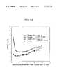
- FIG. 13 is a graph showing full widths at half maximum of gamma ray spectra and pulser signal spectra, respectively when two Stirling refrigerators are run in the same phase and in the opposite phase.
- FIG. 14 is a graph showing the amplitudes of vibrations detected by the acceleration sensor mounted on the front end of the semiconductor radiation detector, respectively when two Stirling refrigerators are run in the same phase and in the opposite phase.
- FIG. 15 is a graph showing full widths at half maximum of gamma ray spectra and pulser signal spectra, respectively when a semiconductor radiation detector of 14 cm 3 is used and when a semiconductor radiation detector of 85 cm 3 is used.
- FIG. 16 is a graph showing the amplitudes of vibrations detected by the acceleration sensor mounted on the front end of the semiconductor radiation detector, respectively when a semiconductor radiation detector of 14 cm 3 is used and when a semiconductor radiation detector of 85 cm 3 is used.
- FIG. 17 is a schematic cross sectional view showing a conventional semiconductor radiation detecting system of a liquid nitrogen cooling type.
- FIG. 18 is a schematic cross sectional view of a conventional semiconductor radiation detecting system using a closed cycle He refrigerator.
- FIGS. 1A to 1C The structure of a radiation detecting system according to an embodiment of the invention will be described with reference to FIGS. 1A to 1C.
- FIG. 1A is a schematic cross sectional view of a radiation detecting system according to an embodiment of the invention.
- Two Stirling refrigerators are constituted by compressors 11a and 11b, isothermal compression parts 12a and 12b, cylinders 23a and 23b continuously coupled to the isothermal compression parts 12a and 12b, and connection pipes 13a and 13b connecting the compressors 11a and 11b and isothermal compression parts 12a and 12b.
- the compressors 11a and 11b are mounted on a base 22.
- a holder 14 and a vacuum vessel 16 are mounted on the base 22 as shown in FIG. 1A.
- the holder 14 fixes the isothermal compression parts 12a and 12b of the Stirling refrigerators.
- the vacuum vessel 16 accommodates the low temperature parts of the Stirling refrigerators and an object to be cooled. Compressed or expanded helium gas is transferred via the connection tubes 13a and 13b between the compressors 11a and 11b and isothermal compression parts 12a and 12b.
- displacers having a cooling function are inserted into the cylinders 23a and 23b to define an expansion space between the displacers and the inner front ends of the cylinders 23a and 23b.
- the displacers reciprocally move in the right and left directions as viewed in FIG. 1A, in response to the change in the pressure with a phase shift from the phase of compressed helium gas introduced into the isothermal compression parts 12a and 12b.
- Helium gas in the expansion space adiabatically expands and cools cooling heads at the front ends of the cylinders 23a and 23b.
- FIG. 1B shows an example of the structure of a stirling refrigerator.
- An isothermal compression ;part 12 and a cylinder 23 are coupled together to define an inner hermetically sealed space.
- a displace 24 has a through gas passage filled with coolant an is inserted into the cylinder 23.
- the displacer 24 is elastically supported at one end of the isothermal compression part 12 by a spring.
- a connection pipe 13 is connected to the isothermal compression part 12 and supplies a work gas to the isothermal compression part 12, the work gas having a periodically changing pressure. The pressure of the work gas is transmitted from the connection pipe 13 to the isothermal compression part 12, gas passage in the displacer 24, and to the expansion space 25.
- a pair of pistons 27a and 27b is disposed in a compressor 11.
- the pistons 27a and 27b facing each other define a compression space therebetween.
- the pistons 27a and 27b are driven each moving toward, or away from the other, by a pair of linear motors constituted by permanent magnets 28a and 28b and moving coils 29a and 29b fixed to the pistons.
- the pulsating gas pressure generated in the compression space is transmitted via the connection pipe 13 to the isothermal compression part 12.
- the isothermal compression part 12 radiates heat to the external space to establish an isothermal gas cycle.
- FIG. 1C schematically shows a gas cycle in the expansion space 25.
- the abscissa represents volume, and the ordinate represents pressure.
- the change between states S1 and S2 is approximately an adiabatic compression process of emitting heat Q.
- the change between states S3 and S4 is approximately an adiabatic expansion process of absorbing heat Q.
- the changes between states S4 and S1 and between states S2 and S3 are approximated to constant volume changes.
- the heat cycle shown in FIG. 1C is an approximated cycle.
- a volume change occurs also in the changes between states S4 and S1 and between states S2 and S3.
- General knowledge about Stirling refrigerators can be found in, for example, U.S. Pat. No. 5,255,521 to Watanabe and U.S. patent application Ser. No. 08/397,843 filed on Mar. 2, 1995, which are incorporated herein by reference.
- the connector 26 is T-character shaped and has a linear portion for coupling the cylinders 23a and 23b and a thick portion having a thickness greater than the linear portion and formed generally at the center of the linear portion. On this thick portion, a radiation detector 15 is mounted.
- the connector 26 is made of a material having a high thermal conductivity such as oxygen free copper specified by JIS-C1020 and aluminum.
- the semiconductor radiation detector may be a Ge or Si radiation detector.
- the semiconductor radiation detector 15, connector 26, and cylinders 23 are hermetically accommodated in the vacuum vessel 16.
- a vacuum valve 17 is connected to the vacuum vessel 16 to evacuate the inside of the vacuum vessel to a high vacuum degree.
- a front stage circuit 18 of preamplifier is mounted on the connector 26 and is electrically connected to the semiconductor radiation detector 15. Signal lines and other wiring lines 19 connected to the front stage circuit 18 of preamplifier are electrically connected via a hermetic seal 20 to a rear stage circuit 21 of preamplifier mounted externally of the vacuum vessel 16. An output signal from the rear stage circuit 21 of preamplifier is supplied to a spectroscopy amplifier 30.
- a high purity Ge radiation detector of a closed end type was used which had a diameter of 34 mm, a length of 15 mm, and a capacity of 14 cm 3 .
- the Ge radiation detector includes a p-type region, an n-type region, and a p-n Junction between these regions.
- Stirling refrigerators were used which had a maximum rated AC operating voltage of 15 V, a current rating of 4 A, and a cooling ability of 1.5 W (80 K).
- compressed helium gas is supplied via the connection pipes 13a and 13b to the isothermal compression parts 12a and 12b.
- the gas is recovered via the same route from the isothermal compression parts 12a and 12b to the compressors 11a and 11b. Helium gas is therefore periodically introduced to, and exhausted from, the isothermal compression parts 12a and 12b.
- radioactive rays 1 are incident upon the semiconductor radiation detector 15, pairs of electrons and holes are generated corresponding in amount to the energy of the radioactive rays 1.
- the pairs of electrons and holes are separately picked up by the n-and p-type regions.
- a radiation detection signal having electric charges corresponding to the energy is therefore generated.
- This radiation detection signal is supplied to the front stage circuit 18 of preamplifier and amplified.
- the signal is thereafter amplified by the rear stage circuit 21 of preamplifier and supplied to the spectroscopy amplifier 30.
- the Stirling refrigerators were operated at a rated cooling ability, the semiconductor radiation detector was able to be cooled to a liquid nitrogen temperature in one hour and thirty minutes.
- FIG. 2 is a graph showing the results of analyzing output signals of the rear stage circuit 21 of preamplifier of the Ge radiation detector shown in FIG. 1A by using a spectrum analyzer.
- the abscissa represents frequency in the unit of kHz, and the ordinate represents noise level in the unit of dBV.
- the unit dBV is 20 log (V/Vo) where Vo is a reference voltage of 1.41 V.
- a bold line a shows a noise level when the Stirling refrigerators of the radiation detecting system shown in FIG. 1A are operated at a rated cooling ability (hereinafter, the arrangement of two Stirling refrigerators in parallel is called a "twin arrangement").
- a fine line b shows a noise level when one Stirling refrigerator is used and driven (hereinafter this arrangement is called a "single arrangement") in place of the twin arrangement of FIG. 1A.
- a broken line c shows a noise level when the cooling heads of the radiation detecting system shown in FIG. 1A are cooled to a predetermined temperature and thereafter the Stirling refrigerators are stopped.
- the noise level is equivalent to that when a conventional system cools the semiconductor radiation detector by liquid nitrogen.
- microphonic noises of about 10 dB are observed at near 4.5 kHz and 6 kHz as indicated by the fine line b.
- microphonic noises reduce as indicated by the bold line a, and good results like liquid nitrogen cooling (broken line) are obtained.
- FIGS. 4 and 5 the results of measuring a 60 Co standard gamma ray source with the radiation detecting system shown in FIG. 1A will be described.
- a system for analyzing a radiation detection signal will be described with reference to FIG. 3.
- FIG. 3 is a block diagram of the system for analyzing a radiation detection signal of the radiation detecting system.
- an output signal from the rear stage circuit 21 of preamplifier is supplied to the spectroscopy amplifier 30.
- the spectroscopy amplifier 30 shapes the waveform of an inputted signal through double integrations and double differentiations at a predetermined waveform shaping time constant to cut background noises and pick up only the signal components as much as possible.
- the signal is then supplied to a pulse height analyzer 31.
- a time during which pairs of electrons and holes are generated by radioactive rays is very short, and a detection signal is characterized by a charge amount generated in a predetermined time period, i.e., by a pulse height.
- the pulse height analyzer 31 analyzes the pulse heights of an inputted signal, distributes them to channels preset for each pulse height to update the contents of a counter of each channel. An output signal from the pulse height analyzer 31 is supplied to a personal computer 32 and is processed.
- the number of channels used was 4096, and the 4096-th channel was set to correspond to a pulse height of about 10 V.
- a pulser 33 supplies constant standard pulse signals as pseudo signals for the radiation detection signal, to the preamplifier 21.
- the pulser 33 may alternatively supply the signals to the spectroscopy amplifier 30. These signals are used for the measurement of a limit in a resolution of only the signal analyzing system, or other factors.
- FIG. 4 shows spectra of standard gamma rays of 1.3 MeV and pulser signals.
- a Ge radiation detector of a closed end type was used as the semiconductor radiation detector.
- the Stirling refrigerators were driven at 12 V, and the waveform shaping time constant of the spectroscopy amplifier was set to 2 ⁇ sec.
- a peak p1 of a gamma ray spectrum appears near at the channel No. 3863, and a peak p2 of the pulser signal spectrum appears near at the channel No. 3957.
- the full width at half maximum (FWHM) of the gamma ray spectrum p1 was 2.2 keV, and that of the pulser signal spectrum p2 was 1.4 keV.
- FWHM of the gamma ray spectrum was 2.6 keV
- that of the pulser signal spectrum was 1.9 keV.
- FWHM of the gamma ray spectrum was 2.2 keV, and that of the pulser signal spectrum was 1.5 keV.
- twin arrangement of the Stirling refrigerators improves an energy resolution more than the single arrangement. It has been found that the twin arrangement provides an energy resolution generally equal to that when the measurement is made after the Stirling refrigerators are stopped.
- FIG. 5 shows full widths at half maximum obtained when the waveform shaping time constant is changed.
- the abscissa represents a waveform shaping time constant in the unit of ⁇ sec
- the ordinate represents a full width at half maximum of a spectrum in the unit of keV.
- Black circles, squares, and triangles represent full widths at half maximum of gamma ray spectra, respectively for the twin arrangement, signal arrangement, and refrigerator stop case.
- White circles, squares, and triangles represent full widths at half maximum of pulser signal spectra, respectively for the twin arrangement, signal arrangement, and refrigerator stop case.
- the drive voltages of the Stirling refrigerators in the twin arrangement and single arrangement were set to 15 V and 11 V, respectively.
- the radiation detector a Ge radiation detector of a closed end type having a capacity of 14 cm 3 was used.
- a resolution equivalent to the refrigerator stop case can be obtained only at the waveform shaping time constant of about 1 ⁇ sec, and rapidly lowers (becomes bad) at the waveform shaping time constant of 2 ⁇ sec or longer.
- a resolution generally equivalent to the refrigerator stop case can be obtained in the range of the waveform shaping time constant of 4 ⁇ sec or shorter. A relatively good resolution can be obtained even at the waveform shaping time constant of 6 ⁇ sec although the resolution lowers slightly.
- the waveform shaping time constant of 0.5 ⁇ sec the resolution of a gamma ray spectrum lowers considerably.
- the reason for this can be given as follows. It takes a certain time, for pairs of electrons and holes generated upon incidence of radioactive rays, to be separated by depletion layers near the p-n Junction and detected as an electrical signal at the electrodes. Since the waveform shaping time constant of 0.5 ⁇ sec is too short, not all current generated upon incidence of radioactive rays can be analyzed.
- the twin arrangement of the Stirling refrigerators provides a good resolution equivalent to the refrigerator stop case in the wide range of the waveform shaping time constant. Improvement of the resolution by the twin arrangement may be considered as resulting from a reduction of microphonic noises caused by a difficulty of vibrations of the radiation detector because of the increased mechanical strength of the mount of the detector. Vibrations in the twin and single arrangements will be described next.
- FIGS. 6A and 6B illustrate a vibration measuring apparatus and a block diagram showing a system for analyzing output signals of the acceleration sensors.
- acceleration sensors 40a, 40b, and 40c are mounted on the front end, top wall, and side wall of a closed end type Ge radiation detector. Vibrations in these three directions were measured.
- output signals from the acceleration sensors 40 were inputted to a DC amplifier 41 and amplified at an amplification factor of 10.
- the amplified signals were observed by a digital oscilloscope 48 in real time, and analyzed by a spectrum analyzer 42.
- FIGS. 7 to 9 are graphs showing the amplitudes of vibrations detected by the acceleration sensors mounted on the front end, top wall, and side wall of the Ge radiation detector.
- Each abscissa represents vibration frequency in the unit of kHz
- each ordinate represents an output of the DC amplifier in the unit of dBV and corresponds to the amplitude of vibrations.
- Curves t designate twin arrangement
- curves s designate single arrangement.
- Numeral 1 attached to the letter designates front end
- numeral 2 designates top wall
- numeral 3 designates side wall.
- the amplitude of vibration reduces as the vibration frequency increases in the range of about 7 kHz and higher, and the amplitude of vibration is small in the range of about 7 kHz or higher although a resonance is locally observed.
- the mechanical vibration levels at the three positions are generally the same.
- the vibration levels detected by the acceleration sensors at the top wall and side wall are larger by about 10 dBV than that detected by the acceleration sensor at the front end. This is considered that from the mechanical point of view, the single arrangement is hard to suppress transverse vibrations orthogonal to the longitudinal direction, whereas transverse vibrations are hard to be generated in the twin arrangement.
- the amplitudes of vibrations are smaller in the twin arrangement in the range of all vibration frequencies than in the single arrangement.
- the cooling heads of two Stirling refrigerators are coupled by the connector of a T-character shape.
- a connector of a different shape may also be used so long as it can suppress vibrations. Examples of other connectors having a different shape will be described.
- FIGS. 10A and 10B are schematic cross sectional views, each showing the cylinders of Stirling refrigerators and a connector connecting the cooling heads of the cylinders.
- a connector 26 having a T-character shape same as the radiation detecting system shown in FIG. 1A is mounted on the cooling heads of the cylinders 23a and 23b.
- a pair of linear elbows 35a and 35b connect a cooling buffer 34 and the cooling heads of the cylinders 23a and 23b, and extend on one linear line.
- a connector 26 having a Y-character shape is mounted.
- the connector has two linear portions 36a and 36b and a rod portion 34.
- the two linear portions 36a and 36b are disposed along two slanted sides of an equilateral triangle whose ends of the bottom side are located at the cooling heads of the two cylinders.
- the rod portion 34 extends from the apex of the two slanted sides of the equilateral triangle.
- FIG. 11 is a graph showing full widths at half maximum of gamma ray spectra and pulser signal spectra, when the waveform shaping time constant is changed.
- a Ge detector of a closed end type having a capacity of 85 cm 3 was used as the semiconductor radiation detector, and the Stirling refrigerator was driven at a voltage of 15 V.
- White and black circles in FIG. 11 represent full widths at half maximum respectively of gamma ray spectra and pulser signal spectra, when the connector of a Y-character shape is used.
- White and black squares in FIG. 11 represent full widths at half maximum respectively of gamma ray spectra and pulser signal spectra, when the connector of a T-character shape is used.
- the full widths at half maximum have almost no significant difference between the connectors of the Y-and T-character shapes in the range of 0.5 to 8 ⁇ s of the waveform shaping time constant.
- FIG. 12 shows the amplitudes of vibrations of a radiation detector when the connectors of the T- and Y-character shapes are used. Vibrations detected by the acceleration sensors at the front end, top wall, and side wall showed generally the same tendency. Therefore, only the amplitudes of vibrations detected with the acceleration sensor at the front end are shown in FIG. 12 as typical examples among the front end, top wall, and side wall.
- a Ge radiation detector of an closed end type having a capacity of 14 cm 3 was used.
- the amplitudes of vibrations have no significant difference between the T- and Y-character shapes and give generally the same tendency that as the vibration frequency becomes higher, the amplitudes of vibrations are gradually reduced.
- the vibration frequency range of 5 kHz or higher the levels of vibrations for the T-character shape is lower than the Y-character shape.
- the absolute values thereof are very small, it can be considered that the semiconductor radiation detector is not practically affected by microphonic noises.
- Vibrations of semiconductor radiation detectors have no significant practical difference between the connectors having the T- and Y-character shapes. Therefore, generally the same resolution can be obtained both for the T- and Y-character shapes.
- the shapes are not limited to T- and Y-character shapes, but any other shapes may be used so long as they ensure the reduction of mechanical vibrations. For example, a V-character shape, a straight line shape, or the like may be used.
- the displacers of two Stirling refrigerators are driven in the same phase.
- the effects of driving the displacers of two Stirling refrigerators in the opposite phase will be described with reference to the experiments results.
- FIG. 13 is a graph showing full widths at half maximum of gamma ray spectra and pulser signal spectra relative to the waveform shaping time constant, respectively when two Stirling refrigerators are run in the same phase and in the opposite phase.
- the semiconductor radiation detector a Ge radiation detector of a closed end type having a capacity of 85 cm 3 was used. A connector of a Y-character shape was used, and the Stirling refrigerator was driven at a voltage of 12 V.
- White and black circles in FIG. 13 represent full widths at half maximum respectively of gamma ray spectra and pulser signal spectra, when the Stirling refrigerators are driven in the same phase.
- White and black squares in FIG. 13 represent full widths at half maximum respectively of gamma ray spectra and pulser signal spectra, when the Stirling refrigerators are driven in the opposite phase.
- FIG. 14 is a graph showing the amplitudes of vibrations of the semiconductor radiation detector, when two Stirling refrigerators are run in the same phase and in the opposite phase. Only the amplitudes of vibrations detected with the acceleration sensor at the front end are shown in FIG. 14 as typical examples among the front end, top wall, and side wall.
- a Ge radiation detector of an closed end type having a capacity of 14 cm 3 was used.
- the amplitudes of vibrations have no significant difference between the same phase drive and opposite phase drive.
- vibrations for the same phase drive are smaller than for the opposite phase drive.
- the absolute values thereof are very small, it can be considered that the semiconductor radiation detector is not practically affected by microphonic noises.
- Vibrations of semiconductor radiation detectors have no significant practical difference between the same phase drive and opposite phase drive of two Stirling refrigerators. Therefore, generally the same resolution can be obtained both for the same phase drive and opposite phase drive.
- FIG. 15 is a graph showing full widths at half maximum of gamma ray spectra and pulser signal spectra relative to the waveform shaping time constant, when semiconductor radiation detectors having capacities of 14 cm 3 and 85 cm 3 are used.
- a connector of a Y-character shape was used, and the Stirling refrigerator was driven in the same phase at a voltage of 12 V.
- White and black circles in FIG. 15 represent full widths at half maximum respectively of gamma ray spectra and pulser signal spectra, when a semiconductor radiation detector having a capacity of 85 cm 3 is used.
- White and black squares in FIG. 15 represent full widths at half maximum respectively of gamma ray spectra and pulser signal spectra, when a semiconductor radiation detector having a capacity of 14 cm 3 is used.
- FIG. 16 is a graph showing the amplitudes of vibrations of the semiconductor radiation detectors having capacities of 14 cm 3 and 85 cm 3 . Only the amplitudes of vibrations detected with the acceleration sensor at the front end are shown in FIG. 16 as typical examples among the front end, top wall, and side wall. A connector having a Y-character shape was used, and the Stirling refrigerators were driven in the same phase.
- vibrations of the semiconductor radiation detector having a capacity of 85 cm 3 are smaller than that having a capacity of 14 cm 3 .
- oxygen free copper or aluminum is used as the material of the connector.
- Other materials may be used if they have a high thermal conductivity and a certain rigidity capable of suppressing vibrations of the cylinders.
- a semiconductor radiation detector is cooled by Stirling refrigerators in the twin arrangement.
- Other detectors may also be cooled, such as an infrared detector.
- Such an infrared detector may be a semiconductor detector or other types of detector.
- the cylinders of two Stirling refrigerators are disposed generally in parallel.
- the cylinders are not necessarily required to be disposed in parallel.
- They may be disposed along two straight lines intersecting at a predetermined angle.
- Two cylinders may be disposed in two slanted sides of an equilateral triangle, with the cooling heads being in substantial contact with each other.
- the connector may be supported on one side of the holder via a plurality of cylinders. In this case, rigidity is increased and vibrations are further suppressed.
- the cooling heads of respective cylinders are disposed along a certain plane and coupled together by the connector, and the isothermal compression parts are disposed on one side of the plane and fixed to the holder.
- a connector of a shape for example, a disk shape, may be used so that the cooling heads of three or more Stirling refrigerators can be thermally coupled thereto.
- the proper number of Stirling refrigerators is preferably determined depending upon a heat capacity of the object to be cooled, a target cooled temperature, a cooling ability of Stirling refrigerators, and the like.
- a Stirling refrigerator instead of a Stirling refrigerator, other refrigerators with mechanically moving members may be used.
Landscapes
- Physics & Mathematics (AREA)
- Engineering & Computer Science (AREA)
- Mechanical Engineering (AREA)
- Thermal Sciences (AREA)
- General Engineering & Computer Science (AREA)
- Life Sciences & Earth Sciences (AREA)
- General Life Sciences & Earth Sciences (AREA)
- General Physics & Mathematics (AREA)
- Geophysics (AREA)
- Measurement Of Radiation (AREA)
Applications Claiming Priority (2)
| Application Number | Priority Date | Filing Date | Title |
|---|---|---|---|
| JP6164010A JP2995144B2 (ja) | 1994-07-15 | 1994-07-15 | 冷却装置を用いた検出装置 |
| JP6-164010 | 1994-07-15 |
Publications (1)
| Publication Number | Publication Date |
|---|---|
| US5970720A true US5970720A (en) | 1999-10-26 |
Family
ID=15785061
Family Applications (1)
| Application Number | Title | Priority Date | Filing Date |
|---|---|---|---|
| US08/501,533 Expired - Fee Related US5970720A (en) | 1994-07-15 | 1995-07-12 | Combined refrigerators and detecting system using the same |
Country Status (2)
| Country | Link |
|---|---|
| US (1) | US5970720A (ja) |
| JP (1) | JP2995144B2 (ja) |
Cited By (7)
| Publication number | Priority date | Publication date | Assignee | Title |
|---|---|---|---|---|
| WO2003078906A1 (de) * | 2002-03-15 | 2003-09-25 | Siemens Aktiengesellschaft | Kälteanlage für zu kühlende teile einer einrichtung |
| US20050097911A1 (en) * | 2003-11-06 | 2005-05-12 | Schlumberger Technology Corporation | [downhole tools with a stirling cooler system] |
| US20080104966A1 (en) * | 2006-11-02 | 2008-05-08 | General Electric Company | Methods and devices for polarized samples for use in MRI |
| US20080173026A1 (en) * | 2006-09-01 | 2008-07-24 | Sumitomo Heavy Industries, Ltd. | Regenerative cryocooler, cylinder used for the regenerative cryocooler, cryopump, recondensing apparatus, superconducting magnet apparatus, and semiconductor detecting apparatus |
| US20140110579A1 (en) * | 2012-10-23 | 2014-04-24 | Advanced Measurement Technology Inc. | Handheld Spectrometer |
| US20230408713A1 (en) * | 2022-05-23 | 2023-12-21 | Oxford Instruments Technologies Oy | Semiconductor radiation detector assembly |
| US12105229B2 (en) | 2021-10-13 | 2024-10-01 | Jeol Ltd. | Radiation detection apparatus and sample analysis apparatus |
Families Citing this family (6)
| Publication number | Priority date | Publication date | Assignee | Title |
|---|---|---|---|---|
| JP3608296B2 (ja) * | 1996-06-21 | 2005-01-05 | セイコーエプソン株式会社 | 低温デバイス装置 |
| JP2005049144A (ja) * | 2003-07-30 | 2005-02-24 | Toshiba Corp | 放射線計測方法 |
| JP4247099B2 (ja) * | 2003-11-28 | 2009-04-02 | 住友重機械工業株式会社 | 動力装置とそれを用いた冷凍機、応用機器 |
| JP5120648B2 (ja) * | 2008-11-07 | 2013-01-16 | 住友重機械工業株式会社 | 極低温冷却装置 |
| JP5283096B2 (ja) * | 2012-03-09 | 2013-09-04 | 住友重機械工業株式会社 | 極低温冷却装置 |
| JP6141022B2 (ja) * | 2013-01-10 | 2017-06-07 | 三菱重工業株式会社 | カメラおよび撮像用センサ冷却方法 |
Citations (7)
| Publication number | Priority date | Publication date | Assignee | Title |
|---|---|---|---|---|
| US5107683A (en) * | 1990-04-09 | 1992-04-28 | Trw Inc. | Multistage pulse tube cooler |
| US5111665A (en) * | 1991-02-19 | 1992-05-12 | General Electric Company | Redundant cryorefrigerator system for a refrigerated superconductive magnet |
| US5113662A (en) * | 1991-02-28 | 1992-05-19 | Mitsubishi Denki Kabushiki Kaisha | Cryogenic refrigerator |
| US5275002A (en) * | 1992-01-22 | 1994-01-04 | Aisin Newhard Co., Ltd. | Pulse tube refrigerating system |
| JPH0613940A (ja) * | 1992-06-29 | 1994-01-21 | Oki Electric Ind Co Ltd | エコーキャンセラ |
| US5385010A (en) * | 1993-12-14 | 1995-01-31 | The United States Of America As Represented By The Secretary Of The Army | Cryogenic cooler system |
| US5392607A (en) * | 1993-07-08 | 1995-02-28 | Hughes Aircraft Company | Stirling-cycle cyrogenic cooler using adaptive feedforward vibration control |
-
1994
- 1994-07-15 JP JP6164010A patent/JP2995144B2/ja not_active Expired - Lifetime
-
1995
- 1995-07-12 US US08/501,533 patent/US5970720A/en not_active Expired - Fee Related
Patent Citations (7)
| Publication number | Priority date | Publication date | Assignee | Title |
|---|---|---|---|---|
| US5107683A (en) * | 1990-04-09 | 1992-04-28 | Trw Inc. | Multistage pulse tube cooler |
| US5111665A (en) * | 1991-02-19 | 1992-05-12 | General Electric Company | Redundant cryorefrigerator system for a refrigerated superconductive magnet |
| US5113662A (en) * | 1991-02-28 | 1992-05-19 | Mitsubishi Denki Kabushiki Kaisha | Cryogenic refrigerator |
| US5275002A (en) * | 1992-01-22 | 1994-01-04 | Aisin Newhard Co., Ltd. | Pulse tube refrigerating system |
| JPH0613940A (ja) * | 1992-06-29 | 1994-01-21 | Oki Electric Ind Co Ltd | エコーキャンセラ |
| US5392607A (en) * | 1993-07-08 | 1995-02-28 | Hughes Aircraft Company | Stirling-cycle cyrogenic cooler using adaptive feedforward vibration control |
| US5385010A (en) * | 1993-12-14 | 1995-01-31 | The United States Of America As Represented By The Secretary Of The Army | Cryogenic cooler system |
Non-Patent Citations (6)
| Title |
|---|
| E. Sakai et al; "Performance of a High-Purity Ge Gamma-Ray Spectrometer System Using a Closed-Cycle Cryogenic Refrigerator"; Feb. 1982; pp. 760-763; IEEE Transactions on Nuclear Science, vol. NS-29, No. 1. |
| E. Sakai et al; Performance of a High Purity Ge Gamma Ray Spectrometer System Using a Closed Cycle Cryogenic Refrigerator ; Feb. 1982; pp. 760 763; IEEE Transactions on Nuclear Science, vol. NS 29, No. 1. * |
| J.M. Marler et al; "Operational Characteristics of a High Purity Germanium Photon Spectrometer Cooled By A Closed-Cycle Cryogenic Refrigerator"; Feb. 1973; pp. 522-527; IEEE Transactions on Nuclear Science; vol. NS-20, No. 1. |
| J.M. Marler et al; Operational Characteristics of a High Purity Germanium Photon Spectrometer Cooled By A Closed Cycle Cryogenic Refrigerator ; Feb. 1973; pp. 522 527; IEEE Transactions on Nuclear Science; vol. NS 20, No. 1. * |
| R.E. Stone et al; "Performance of a Gamma-Ray and X-Ray Spectrometer Utilizing Germanium and Si (Li) Detectors Cooled by a Closed-Cycle Cryogenic Mechanical Refrigerator"; Feb. 1986 pp. 299-302; IEEE Transactions on Nuclear Science, vol. NS-33, No. 1. |
| R.E. Stone et al; Performance of a Gamma Ray and X Ray Spectrometer Utilizing Germanium and Si (Li) Detectors Cooled by a Closed Cycle Cryogenic Mechanical Refrigerator ; Feb. 1986 pp. 299 302; IEEE Transactions on Nuclear Science, vol. NS 33, No. 1. * |
Cited By (11)
| Publication number | Priority date | Publication date | Assignee | Title |
|---|---|---|---|---|
| WO2003078906A1 (de) * | 2002-03-15 | 2003-09-25 | Siemens Aktiengesellschaft | Kälteanlage für zu kühlende teile einer einrichtung |
| US20050150242A1 (en) * | 2002-03-15 | 2005-07-14 | Siemens Aktiengesellschaft | Refrigeration plant for parts of installation, which are to be chilled |
| US7174737B2 (en) | 2002-03-15 | 2007-02-13 | Siemens Aktiengesellschaft | Refrigeration plant for parts of installation, which are to be chilled |
| US20050097911A1 (en) * | 2003-11-06 | 2005-05-12 | Schlumberger Technology Corporation | [downhole tools with a stirling cooler system] |
| FR2862081A1 (fr) * | 2003-11-06 | 2005-05-13 | Schlumberger Services Petrol | Outils de fond de trou dotes d'un systeme de refroidissement a cycle de stirling |
| US20080173026A1 (en) * | 2006-09-01 | 2008-07-24 | Sumitomo Heavy Industries, Ltd. | Regenerative cryocooler, cylinder used for the regenerative cryocooler, cryopump, recondensing apparatus, superconducting magnet apparatus, and semiconductor detecting apparatus |
| US20080104966A1 (en) * | 2006-11-02 | 2008-05-08 | General Electric Company | Methods and devices for polarized samples for use in MRI |
| US7631507B2 (en) * | 2006-11-02 | 2009-12-15 | General Electric Company | Methods and devices for polarized samples for use in MRI |
| US20140110579A1 (en) * | 2012-10-23 | 2014-04-24 | Advanced Measurement Technology Inc. | Handheld Spectrometer |
| US12105229B2 (en) | 2021-10-13 | 2024-10-01 | Jeol Ltd. | Radiation detection apparatus and sample analysis apparatus |
| US20230408713A1 (en) * | 2022-05-23 | 2023-12-21 | Oxford Instruments Technologies Oy | Semiconductor radiation detector assembly |
Also Published As
| Publication number | Publication date |
|---|---|
| JP2995144B2 (ja) | 1999-12-27 |
| JPH0828981A (ja) | 1996-02-02 |
Similar Documents
| Publication | Publication Date | Title |
|---|---|---|
| US5970720A (en) | Combined refrigerators and detecting system using the same | |
| US10304656B2 (en) | Ion beam device | |
| US7161150B2 (en) | Handheld isotope identification system | |
| JPWO2016084162A6 (ja) | イオンビーム装置 | |
| JP7761494B2 (ja) | 極低温装置 | |
| US8443673B2 (en) | High sensitivity geophone | |
| US5531074A (en) | Electronic device freezed by intermittently driven refrigerator | |
| US7538649B2 (en) | Superconducting electromagnet | |
| US8440966B2 (en) | Fourier transform ion cyclotron resonance mass spectrometer using a cryo-detection system | |
| US5552609A (en) | Electric-cooled type semiconductor radioactive ray detector | |
| US20060045754A1 (en) | Ion pump for cryogenic magnet apparatus | |
| Wang et al. | Performance characteristics of a 4 K pulse tube in current applications | |
| GB2325045A (en) | Energy-dispersive-type semiconductor X-ray detector | |
| EP0265486B1 (en) | Modular photon detector cryostat assembly and system | |
| JP3635897B2 (ja) | 電磁駆動式往復動機構 | |
| CN216928214U (zh) | 超导磁体装置 | |
| EP0585001A2 (en) | X-ray spectrometry detector | |
| JP7649875B2 (ja) | スターリングクーラを有するnmr磁石システム | |
| Stone et al. | Performance of a gamma-ray and x-ray spectrometer utilizing germanium and Si (Li) detectors cooled by a closed-cycle cryogenic mechanical refrigerator | |
| Marler et al. | Operational Characteristics of a high purity germanium photon spectrometer cooled by a closed-cycle cryogenic refrigerator | |
| US7151269B2 (en) | Sample inspection apparatus | |
| JP3362141B2 (ja) | 磁気測定装置および極低温容器 | |
| Katagiri et al. | General-purpose germanium gamma-ray detector cooled with two Stirling refrigerators | |
| Collins et al. | Performance characterization of the TRW 35K pulse tube cooler | |
| SU1716409A1 (ru) | Датчик дл рентгенорадиометрического анализатора с полупроводниковым детектором |
Legal Events
| Date | Code | Title | Description |
|---|---|---|---|
| AS | Assignment |
Owner name: JAPAN ATOMIC ENERGY RESEARCH INSTITUTE, JAPAN Free format text: ASSIGNMENT OF ASSIGNORS INTEREST;ASSIGNORS:KATAGIRI, MASAKI;KOBAYASHI, YOSHII;TAGUCHI, YOSHITO;AND OTHERS;REEL/FRAME:007606/0240;SIGNING DATES FROM 19950630 TO 19950706 Owner name: SUMITOMO HEAVY INDUSTRIES, LTD., JAPAN Free format text: ASSIGNMENT OF ASSIGNORS INTEREST;ASSIGNORS:KATAGIRI, MASAKI;KOBAYASHI, YOSHII;TAGUCHI, YOSHITO;AND OTHERS;REEL/FRAME:007606/0240;SIGNING DATES FROM 19950630 TO 19950706 |
|
| FEPP | Fee payment procedure |
Free format text: PAYOR NUMBER ASSIGNED (ORIGINAL EVENT CODE: ASPN); ENTITY STATUS OF PATENT OWNER: LARGE ENTITY |
|
| FPAY | Fee payment |
Year of fee payment: 4 |
|
| FPAY | Fee payment |
Year of fee payment: 8 |
|
| REMI | Maintenance fee reminder mailed | ||
| LAPS | Lapse for failure to pay maintenance fees | ||
| STCH | Information on status: patent discontinuation |
Free format text: PATENT EXPIRED DUE TO NONPAYMENT OF MAINTENANCE FEES UNDER 37 CFR 1.362 |
|
| FP | Lapsed due to failure to pay maintenance fee |
Effective date: 20111026 |