US5979327A - Method and apparatus for blasthole stemming - Google Patents
Method and apparatus for blasthole stemming Download PDFInfo
- Publication number
- US5979327A US5979327A US09/066,427 US6642798A US5979327A US 5979327 A US5979327 A US 5979327A US 6642798 A US6642798 A US 6642798A US 5979327 A US5979327 A US 5979327A
- Authority
- US
- United States
- Prior art keywords
- blasthole
- explosives
- plugging device
- outer member
- explosive
- Prior art date
- Legal status (The legal status is an assumption and is not a legal conclusion. Google has not performed a legal analysis and makes no representation as to the accuracy of the status listed.)
- Expired - Fee Related
Links
- 238000000034 method Methods 0.000 title claims abstract description 16
- 239000002360 explosive Substances 0.000 claims abstract description 67
- 239000000463 material Substances 0.000 claims abstract description 29
- 239000012530 fluid Substances 0.000 claims abstract description 19
- 230000000977 initiatory effect Effects 0.000 claims description 8
- 238000005086 pumping Methods 0.000 claims description 8
- 239000000203 mixture Substances 0.000 claims description 4
- 239000000839 emulsion Substances 0.000 description 4
- 230000002706 hydrostatic effect Effects 0.000 description 3
- 239000007788 liquid Substances 0.000 description 3
- 238000005065 mining Methods 0.000 description 3
- XLYOFNOQVPJJNP-UHFFFAOYSA-N water Substances O XLYOFNOQVPJJNP-UHFFFAOYSA-N 0.000 description 3
- 238000005422 blasting Methods 0.000 description 2
- 239000000470 constituent Substances 0.000 description 2
- 239000007789 gas Substances 0.000 description 2
- 238000012986 modification Methods 0.000 description 2
- 230000004048 modification Effects 0.000 description 2
- 239000011435 rock Substances 0.000 description 2
- 239000004793 Polystyrene Substances 0.000 description 1
- 230000000903 blocking effect Effects 0.000 description 1
- 239000003245 coal Substances 0.000 description 1
- 238000005520 cutting process Methods 0.000 description 1
- 238000005474 detonation Methods 0.000 description 1
- 230000000694 effects Effects 0.000 description 1
- 229920001971 elastomer Polymers 0.000 description 1
- 238000004880 explosion Methods 0.000 description 1
- -1 gravel Substances 0.000 description 1
- 230000005484 gravity Effects 0.000 description 1
- 238000003780 insertion Methods 0.000 description 1
- 230000037431 insertion Effects 0.000 description 1
- 230000001788 irregular Effects 0.000 description 1
- 239000013618 particulate matter Substances 0.000 description 1
- 239000004033 plastic Substances 0.000 description 1
- 229920003023 plastic Polymers 0.000 description 1
- 229920001084 poly(chloroprene) Polymers 0.000 description 1
- 229920000642 polymer Polymers 0.000 description 1
- 229920002223 polystyrene Polymers 0.000 description 1
- 229920002635 polyurethane Polymers 0.000 description 1
- 239000004814 polyurethane Substances 0.000 description 1
- 239000004576 sand Substances 0.000 description 1
- 238000007789 sealing Methods 0.000 description 1
- 239000002689 soil Substances 0.000 description 1
- 239000000725 suspension Substances 0.000 description 1
- 229920001059 synthetic polymer Polymers 0.000 description 1
- 239000011800 void material Substances 0.000 description 1
- 239000002023 wood Substances 0.000 description 1
Images


Classifications
-
- F—MECHANICAL ENGINEERING; LIGHTING; HEATING; WEAPONS; BLASTING
- F42—AMMUNITION; BLASTING
- F42D—BLASTING
- F42D1/00—Blasting methods or apparatus, e.g. loading or tamping
- F42D1/08—Tamping methods; Methods for loading boreholes with explosives; Apparatus therefor
- F42D1/10—Feeding explosives in granular or slurry form; Feeding explosives by pneumatic or hydraulic pressure
Definitions
- the present invention relates to a method and apparatus for use in charging blastholes.
- blasting In mining operations the main objective of blasting is to break rock and shift material in a useful way. When an explosive charge explodes there is a powerful force exerted in all directions and any earth surrounding the explosive charge will break along the line of least resistance. In order to achieve an optimal result in blasting the location and degree of confinement of an explosive charge must be carefully designed. In mining applications this generally consists of locating explosive charges in blastholes drilled in ore, rock, coal or the like. Factors such as the diameter, length, angle and spacing of the blastholes are critical to the success of a blast.
- Charging a newly drilled blasthole with explosives generally involves careful placement of an initiation device such as a detonator, a primer and bulk and/or packaged explosives.
- initiation devices such as a detonator, a primer and bulk and/or packaged explosives.
- Detonators are small, compact high energy explosives which can initiate a larger body of explosive such as a primer which in turn may detonate with enough force to initiate bulk or packaged explosives.
- the nature, quantity and arrangement of the initiation device, primer and bulk or packaged explosives in a blasthole has a large influence on the results of a blast.
- the blasthole is not completely filled with explosive charges. Often there is a gap between the top of the column of explosive charge and the collar of the blasthole which is either left open or filled with non-explosive material called stemming.
- the column itself may not necessarily be continuous; sometimes the column comprises several charges or short columns separated by inert material or devices referred to as decks are inserted into blastholes to provide discontinuities in the column of explosive. Decking tends to lower the explosion pressure in a blasthole and provide a more even distribution of energy than can be achieved in the absence of decking.
- Australian Patent Application No. 41907/93 describes an inflatable plugging device for stemming blastholes.
- This particular device comprises a flexible, inflatable body member which is contained within an inflexible container. Inflation of the flexible member acts to engage the walls of a blasthole to keep the device in place and maintain suspension of the stemming.
- This device does not necessarily eliminate the use of stemming material and it is not always possible for a preformed, inflexible container to conform to the irregular cross section of a blasthole and thus form a seal.
- Blastholes are commonly charged with bulk explosives by pumping or pneumatically conveying the bulk explosive through a loading hose into the blasthole.
- One of the drawbacks of most of the plugging devices of the prior art is that when such devices are used for decking, it is necessary to interrupt the charging of the blasthole with explosive in order to put the plugging device in place.
- When charging a deep blasthole full of emulsion explosive it is very inconvenient and inefficient to have to cease pumping or pneumatically conveying the emulsion and remove the loading hose in order to insert a plugging device.
- This method of operation is particularly inconvenient when charging upholes where the bulk emulsion already in the blasthole starts to slowly flow out of the hole under the influence of gravity before the plugging device is pushed into place.
- a plugging device can be provided which can be placed in position in a blasthole prior to charging and bulk explosives pumped through the device.
- the present invention provides a device for plugging a blasthole which device comprises:
- an inner member comprising a conduit for the passage of fluid bulk explosives material said conduit including a valve means adapted to allow passage of the explosives material in only one direction;
- the inner member essentially comprises a conduit or passage with an opening or inlet port at one end and an opening or outlet port at the other end through which fluid bulk explosive may be passed.
- a valve prevents back flow of fluid bulk explosive.
- the outer member performs the function of bracing the plugging device against the walls of a blasthole such that the device forms a good seal with the blasthole walls and is prevented from slipping out of the blasthole.
- the outer member substantially conforms to the general shape of the blasthole.
- the outer member is constructed of a deformable material which provides good contact between the device and the walls of the blasthole.
- Suitable materials include natural polymeric materials such as rubber, synthetic polymers such as expanded polyurethanes or expanded polystyrenes, neoprene and the like.
- the outer member may also be inflatable so that the plugging device can be easily pushed into place along a blasthole and then the outer member inflated so as to provide good contact with the blasthole walls.
- the outer member may be inflated by a source of fluid material located externally such as a cylinder of gas or liquid which is kept under pressure or a reservoir of liquid which may be pumped into the flexible container. Depending on the fluid used it may be possible to pressurise the outer member.
- the flexible container may comprise a filling means such as a non-return valve, bleed valve, needle valve or any other convenient means for controlling fluid flow.
- the fluid material for inflating the flexible container may be any convenient matter and includes liquids, gases or finely divided particulate matter. Water and air are particularly inexpensive and convenient fluid materials.
- the outer member and the inner member comprise separate elements which may be assembled to give the plugging device of the present invention.
- the outer member comprises a flexible container in the shape of cylinder comprising an essentially tubular conduit or passage along its axis or a flexible container in the shape of a toroid.
- the outer member may form an inflatable vessel or bag, the surface of which defines a cylinder comprising an essentially tubular conduit or passage along its axis or an inflatable vessel or bag the surface of which defines a toroid.
- the inner member of such a preferred embodiment of the present invention comprises a tube or conduit adapted to be fitted into the essentially tubular conduit or passage in the outer member and which includes a valve means.
- Such an inner member may be conveniently referred to as a "liner” as it in effect "lines” the conduit or passage in the outer member when the inner and outer members are assembled to form the plugging device of the present invention.
- the liner is tubular in shape and integral with the valve means.
- One end of the liner may comprise the inlet port, while the other end of the liner comprises the outlet port.
- the inlet port may be adapted for attachment of the explosives loading hose or alternatively the loading hose may be passed through the inlet port, part way into the passage or liner.
- valve means of the device of the present invention is located at the end of the liner nearest the outlet.
- the liner may be adapted to allow limited movement of a ball within the sleeve and thus form a ball valve.
- the movement of the ball may be limited by tapered fins protruding from the inner wall of the liner or a cage or the like.
- the liner and/or valve means may be constructed of any convenient material such as polymers.
- valve means of the device of the current invention permits fluid bulk explosive to be pumped through the passage of the plugging device into the blasthole but prevents any fluid bulk explosive flow in the opposite direction by sealing off the passage.
- the hydrostatic head should be sufficient to cause the valve to close off the passage.
- the plugging device of the current invention is located in place in a blasthole and fluid bulk explosive is pumped or pneumatically conveyed into the blasthole. Initially the bulk explosive passes through the plugging device to fill the space between the end of the blasthole and the plugging device. As this happens, air is displaced and it may be necessary to provide means such as a bleed tube by which the air can vent from the blasthole.
- the device of the current invention is provided with a channel for a bleed tube. It will be apparent to those skilled in the art that an air bleed tube will not be required in broken ground or in open holes from which displaced air can readily escape.
- the current invention also provides a method of charging a blasthole using the device of the current invention.
- the method comprises the steps of:
- the plugging device may be pushed into place in the blasthole using the end of the loading hose.
- the plugging device of the current invention can be used at any position within a blasthole or for any convenient purpose.
- the plugging device of the current invention can be used instead of stemming material or to hold stemming material in place.
- the stemming device can also be used in a decked blasthole between charges of explosives or between stemming material and explosives charges.
- the current invention provides a further method of charging a blasthole.
- the method comprises the steps of:
- the plugging device of the current invention is used in a decked blasthole to separate charges of explosives from each other or separate explosives charges from inert material
- the current invention provides a further method of charging a blasthole. The method comprises the steps of:
- step (d) repeating step (b) and step (c) until the blasthole is filled.
- the explosives composition would be pneumatically conveyed or pumped into the blasthole through a loading hose but it may be tipped or augered into the blasthole.
- the inert material may be any suitable non-explosive material known in the explosives field such as raw soil, gravel, sand and the like.
- the inert material may be charged into the blasthole by any convenient means including pneumatic conveying or pumping.
- the end of an explosives loading hose or stem material loading hose is inserted into the plugging device of the current invention, the plugging device is located in place in the blasthole and explosives composition or stemming material is pumped through the plugging device.
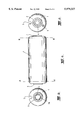
- FIG. 1 depicts one embodiment of the outer member of the plugging device of the current invention
- FIG. 2 is a longitudinal cross section of the liner of the plugging device, dismantled to show its constituent members
- FIG. 3 is a cross section of the assembled plugging device.
- FIG. 4 depicts the device of the current invention in use.
- FIG. 1a shows the outward appearance of one embodiment of the outer member (1) of the plugging device which is generally cylindrical in shape and inflatable.
- the inlet port (2) and outlet port (3) can be clearly seen and are formed from the liner of the outer member.
- FIG. 1b is a view across the section AA' of FIG. 1a and shows the outlet port (3) and the passage (4) which passes between the inlet and outlet ports. Tapered fins (3a) prevent a ball valve in the liner from escaping from the passage.
- a channel (5) in the outer member (1) provides a conduit for a bleed tube.
- FIG. 1c is a view across the section BB' of FIG. 1a showing the inlet port (2), the passage (4) and the channel (5).
- a needle valve (6) is provided for inflation of the outer member.
- FIG. 2 is a cross section of the liner of the plugging device of the current invention, dismantled to show its constituent pieces.
- the liner is generally tubular in shape, comprising two body members (7a, 7b) which can hold together by interference fit.
- the inlet port (2) may be fitted with an inlet seal (8).
- a ball (9) fits into the liner near the outlet port (3).
- the bulk explosive flows around the ball as the liner near the outlet is of greater diameter than the ball.
- the hydrostatic head of bulk explosive forces the ball away from the outlet, towards the parts of the liner of narrower diameter where the ball lodges, blocking the liner and preventing back flow of bulk explosive out of the plugging device.
- FIG. 3 is a cross section of the assembled plugging device.
- the two body members of the liner (7a,7b), the ball (9) and inlet seal (8) can be seen located within the outer member (1).
- An o-ring (10) helps to seal around the hose used for pumping bulk explosive.
- FIG. 4 depicts the plugging device of the current invention in place in an uphole.
- a detonator attached to a length of signal tube (12) (or alternatively leg wires) is inserted into a primer (11).
- the primer is then located in position in a blasthole, preferably using a STOPEPRIME primer locater.
- STOPEPRIME is a trade mark of ICI Australia Operations Proprietary Limited.
- a bleed tube (14) is then positioned in the blasthole.
- a plugging device of the current invention is put in place near the collar of the blasthole and the outer member inflated using compressed air. Care is taken that the bleed tube passes along the channel in the outer member of the plugging device. It may be convenient (but not mandatory) that the signal tube also passes along the channel.
- an explosive loading hose (13) is inserted into the plugging device and used to push the plugging device into position in the blasthole. Fluid bulk explosive is then pumped through the plugging device into the blasthole. As the blasthole fills with explosive emulsion, air is displaced from the blasthole and escapes through the bleed tube. By the time the column of bulk explosive has risen from the collar area of the blasthole to the toe, the hydrostatic head of the column is sufficient to push the ball of the ball valve down and seal off the passage in the plugging device. The loading hose is subsequently removed and the blasthole is ready for detonation.
- the plugging device of the current invention can be used as the sole means of plugging a blasthole or may be used in conjunction with other plugging means such as drill cuttings or the like. In some mining applications it may occur that the blasthole is open at both ends or that the toe of the blasthole is likely to break through surrounding or into a fissure, void, old tunnel or the like. In this situation it may be advisable to locate the plugging device of the current invention at the toe and the collar of the blasthole.
Landscapes
- Life Sciences & Earth Sciences (AREA)
- General Life Sciences & Earth Sciences (AREA)
- Engineering & Computer Science (AREA)
- General Engineering & Computer Science (AREA)
- Drilling And Exploitation, And Mining Machines And Methods (AREA)
- Pipe Accessories (AREA)
Applications Claiming Priority (3)
| Application Number | Priority Date | Filing Date | Title |
|---|---|---|---|
| AUPN6377A AUPN637795A0 (en) | 1995-11-03 | 1995-11-03 | Method and apparatus for blasthole stemming |
| AUPN6377 | 1995-11-03 | ||
| PCT/AU1996/000690 WO1997017588A1 (en) | 1995-11-03 | 1996-11-01 | Method and apparatus for blasthole stemming |
Publications (1)
| Publication Number | Publication Date |
|---|---|
| US5979327A true US5979327A (en) | 1999-11-09 |
Family
ID=3790702
Family Applications (1)
| Application Number | Title | Priority Date | Filing Date |
|---|---|---|---|
| US09/066,427 Expired - Fee Related US5979327A (en) | 1995-11-03 | 1996-11-01 | Method and apparatus for blasthole stemming |
Country Status (6)
| Country | Link |
|---|---|
| US (1) | US5979327A (id) |
| CN (1) | CN1201517A (id) |
| AU (1) | AUPN637795A0 (id) |
| ID (1) | ID19183A (id) |
| WO (1) | WO1997017588A1 (id) |
| ZA (1) | ZA969227B (id) |
Cited By (10)
| Publication number | Priority date | Publication date | Assignee | Title |
|---|---|---|---|---|
| US6209458B1 (en) * | 1996-11-01 | 2001-04-03 | Orica Australia Pty Ltd. | Inflatable plugs for charging blastholes |
| US6386111B1 (en) * | 1996-11-04 | 2002-05-14 | Advanced Blasting Technology, Inc. | Stemming arrangement and method for blast holes |
| US20040152301A1 (en) * | 1998-07-31 | 2004-08-05 | Imran Hashim | Method and apparatus for forming improved metal interconnects |
| US20040237826A1 (en) * | 2001-06-20 | 2004-12-02 | Mendelawitz David James | Protection of blast holes |
| WO2005003678A3 (en) * | 2003-07-02 | 2006-05-18 | Dyno Nobel Inc | Blast hole liner system and method for the same |
| US20090314177A1 (en) * | 2008-06-19 | 2009-12-24 | George Laszlo | Tamping Device |
| US8468944B2 (en) | 2008-10-24 | 2013-06-25 | Battelle Memorial Institute | Electronic detonator system |
| CN103256873A (zh) * | 2013-05-22 | 2013-08-21 | 赵明 | 一种矿用风压炮泥机 |
| US10619987B1 (en) * | 2019-01-02 | 2020-04-14 | Dyno Nobel Inc. | Blasthole guards and related systems and methods |
| CN114812324A (zh) * | 2022-05-05 | 2022-07-29 | 四川省永生爆破工程有限公司 | 炸药现场混装的炮孔装药装置 |
Families Citing this family (14)
| Publication number | Priority date | Publication date | Assignee | Title |
|---|---|---|---|---|
| WO1998041811A1 (en) * | 1997-03-14 | 1998-09-24 | Silverport Pty. Ltd. | Device to facilitate the placing of slurries in up-holes |
| US6339992B1 (en) | 1999-03-11 | 2002-01-22 | Rocktek Limited | Small charge blasting apparatus including device for sealing pressurized fluids in holes |
| US6332401B1 (en) | 1999-03-11 | 2001-12-25 | Rocktek Limited | Method and apparatus for pressure wave suppression in small-charge blasting |
| AU722846B1 (en) * | 1999-03-11 | 2000-08-10 | Rockmin Pty Ltd | A method and apparatuses for pressure wave suppression and fly rock control in small-charge blasting |
| KR100467483B1 (ko) * | 2002-06-28 | 2005-01-24 | 강대우 | 암반발파공 밀폐마개 |
| CN102047069B (zh) * | 2008-06-05 | 2014-03-05 | 马克萨姆丹特克斯南非(私人)有限公司 | 用于以可泵送材料填充向上定向的孔眼的方法和装置 |
| AU2011237288B2 (en) * | 2010-04-06 | 2014-07-31 | Sandvik Mining And Construction Rsa (Pty) Ltd | A rock breaking product |
| CN102564252B (zh) * | 2012-03-15 | 2013-09-04 | 李浩镕 | 一种组合式炮堵装置 |
| RU2709123C1 (ru) * | 2018-12-28 | 2019-12-16 | Акционерная Компания "АЛРОСА" (публичное акционерное общество) (АК "АЛРОСА" (ПАО)) | Устройство для заряжания восстающих скважин и способ заряжания |
| CN109579648B (zh) * | 2019-01-18 | 2023-11-24 | 中铁工程装备集团隧道设备制造有限公司 | 炮眼孔内炸药的快速安装装置及方法 |
| CN112902776B (zh) * | 2021-03-02 | 2023-11-28 | 陕西新通宇彤智能科技有限公司 | 一种高压电磁力爆破装置的膨胀密封套 |
| CN114264207B (zh) * | 2021-08-16 | 2024-01-09 | 北方工业大学 | 一种炮眼自动封堵炮泥装置及炮眼封堵方法 |
| CN114485303B (zh) * | 2022-03-09 | 2024-06-14 | 新疆大学 | 一种上向孔装药防返粉装置 |
| CN117846594B (zh) * | 2024-01-12 | 2024-05-31 | 中国矿业大学 | 一种固-液-气三相耦合介质爆破掘进巷/隧道的方法 |
Citations (10)
| Publication number | Priority date | Publication date | Assignee | Title |
|---|---|---|---|---|
| US1642118A (en) * | 1926-07-26 | 1927-09-13 | Lindner Werner | Blasting-bore closure |
| GB320765A (en) * | 1928-10-16 | 1929-10-24 | David Hodge | Improvements relating to tampings for bore-holes for blasting cartridges |
| US1751015A (en) * | 1928-12-03 | 1930-03-18 | Mora John | Blasting device |
| US1772994A (en) * | 1928-09-08 | 1930-08-12 | Halverson Frank August | Blasting device |
| GB812888A (en) * | 1958-01-08 | 1959-05-06 | Stephen Fink | Bore-hole closure for blasting work |
| GB2211587A (en) * | 1987-10-23 | 1989-07-05 | Ici Australia Operations | Conduit constriction means |
| US5092245A (en) * | 1990-07-18 | 1992-03-03 | The United States Of America As Represented By The Secretary Of The Army | Explosive stemming device |
| AU3043692A (en) * | 1991-12-24 | 1993-07-01 | Sanleo Holdings Pty Ltd | Inflatable borehole plug assemblies |
| AU4121093A (en) * | 1992-06-15 | 1993-12-23 | Orica Explosives Technology Pty Ltd | Method of uphole loading |
| AU4190793A (en) * | 1992-07-22 | 1994-01-27 | Mti Group Pty Ltd | Inflatable devices for suspending explosives and stemming materials in boreholes |
-
1995
- 1995-11-03 AU AUPN6377A patent/AUPN637795A0/en not_active Abandoned
-
1996
- 1996-11-01 US US09/066,427 patent/US5979327A/en not_active Expired - Fee Related
- 1996-11-01 ZA ZA969227A patent/ZA969227B/xx unknown
- 1996-11-01 WO PCT/AU1996/000690 patent/WO1997017588A1/en not_active Ceased
- 1996-11-01 CN CN96198055A patent/CN1201517A/zh active Pending
- 1996-11-04 ID IDP963187A patent/ID19183A/id unknown
Patent Citations (10)
| Publication number | Priority date | Publication date | Assignee | Title |
|---|---|---|---|---|
| US1642118A (en) * | 1926-07-26 | 1927-09-13 | Lindner Werner | Blasting-bore closure |
| US1772994A (en) * | 1928-09-08 | 1930-08-12 | Halverson Frank August | Blasting device |
| GB320765A (en) * | 1928-10-16 | 1929-10-24 | David Hodge | Improvements relating to tampings for bore-holes for blasting cartridges |
| US1751015A (en) * | 1928-12-03 | 1930-03-18 | Mora John | Blasting device |
| GB812888A (en) * | 1958-01-08 | 1959-05-06 | Stephen Fink | Bore-hole closure for blasting work |
| GB2211587A (en) * | 1987-10-23 | 1989-07-05 | Ici Australia Operations | Conduit constriction means |
| US5092245A (en) * | 1990-07-18 | 1992-03-03 | The United States Of America As Represented By The Secretary Of The Army | Explosive stemming device |
| AU3043692A (en) * | 1991-12-24 | 1993-07-01 | Sanleo Holdings Pty Ltd | Inflatable borehole plug assemblies |
| AU4121093A (en) * | 1992-06-15 | 1993-12-23 | Orica Explosives Technology Pty Ltd | Method of uphole loading |
| AU4190793A (en) * | 1992-07-22 | 1994-01-27 | Mti Group Pty Ltd | Inflatable devices for suspending explosives and stemming materials in boreholes |
Cited By (12)
| Publication number | Priority date | Publication date | Assignee | Title |
|---|---|---|---|---|
| US6209458B1 (en) * | 1996-11-01 | 2001-04-03 | Orica Australia Pty Ltd. | Inflatable plugs for charging blastholes |
| US6386111B1 (en) * | 1996-11-04 | 2002-05-14 | Advanced Blasting Technology, Inc. | Stemming arrangement and method for blast holes |
| US20040152301A1 (en) * | 1998-07-31 | 2004-08-05 | Imran Hashim | Method and apparatus for forming improved metal interconnects |
| US20040237826A1 (en) * | 2001-06-20 | 2004-12-02 | Mendelawitz David James | Protection of blast holes |
| WO2005003678A3 (en) * | 2003-07-02 | 2006-05-18 | Dyno Nobel Inc | Blast hole liner system and method for the same |
| US20090314177A1 (en) * | 2008-06-19 | 2009-12-24 | George Laszlo | Tamping Device |
| US8468944B2 (en) | 2008-10-24 | 2013-06-25 | Battelle Memorial Institute | Electronic detonator system |
| US8746144B2 (en) | 2008-10-24 | 2014-06-10 | Battelle Memorial Institute | Electronic detonator system |
| CN103256873A (zh) * | 2013-05-22 | 2013-08-21 | 赵明 | 一种矿用风压炮泥机 |
| US10619987B1 (en) * | 2019-01-02 | 2020-04-14 | Dyno Nobel Inc. | Blasthole guards and related systems and methods |
| CN114812324A (zh) * | 2022-05-05 | 2022-07-29 | 四川省永生爆破工程有限公司 | 炸药现场混装的炮孔装药装置 |
| CN114812324B (zh) * | 2022-05-05 | 2023-01-20 | 四川省永生爆破工程有限公司 | 炸药现场混装的炮孔装药装置 |
Also Published As
| Publication number | Publication date |
|---|---|
| WO1997017588A1 (en) | 1997-05-15 |
| CN1201517A (zh) | 1998-12-09 |
| ZA969227B (en) | 1997-05-03 |
| ID19183A (id) | 1998-06-28 |
| AUPN637795A0 (en) | 1995-11-30 |
Similar Documents
| Publication | Publication Date | Title |
|---|---|---|
| US5979327A (en) | Method and apparatus for blasthole stemming | |
| US3696703A (en) | Blasting agent package | |
| US8381653B2 (en) | Method and apparatus for charging an upwardly oriented hole with a pumpable material | |
| CA2110638C (en) | Expansion foam borehole plug and method | |
| AU595887B2 (en) | Borehole plug and method | |
| US5192819A (en) | Bulk explosive charger | |
| US3541797A (en) | Apparatus for loading boreholes | |
| US10942017B2 (en) | Inflatable blasthole plug assembly | |
| CA1239550A (en) | Method for charging flowable explosives into upwardly extending boreholes | |
| US6209458B1 (en) | Inflatable plugs for charging blastholes | |
| US20130199393A1 (en) | Rock Breaking Product | |
| WO2009109008A1 (en) | Borehole plug with a primary bladder inflation device and a pressure booster | |
| US5035286A (en) | Methods and apparatus for field blasting of earth formations using inflatable devices for suspending explosives in boreholes | |
| AU668946B2 (en) | Method of uphole loading | |
| AU2001266433B2 (en) | Method and apparatus for providing a primer with a detonator in a borehole | |
| AU722007C (en) | Method and apparatus for blasthole stemming | |
| US4919203A (en) | Methods and apparatus for field blasting of earth formations using inflatable devices for suspending explosives in bore holes | |
| CA2236002A1 (en) | Method and apparatus for blasthole stemming | |
| AU2001266433A1 (en) | Method and apparatus for providing a primer with a detonator in a borehole | |
| AU724035B2 (en) | Stemming arrangement and method for blast holes | |
| AU717591B2 (en) | Method and apparatus for use in charging blastholes | |
| WO1998041811A1 (en) | Device to facilitate the placing of slurries in up-holes | |
| US20090277354A1 (en) | Blasting air tube with sleeve, and method | |
| US3974656A (en) | Method and apparatus for excluding water or other material from a blast hole in rock | |
| AU2007201040A1 (en) | Improvements in explosives decking systems |
Legal Events
| Date | Code | Title | Description |
|---|---|---|---|
| AS | Assignment |
Owner name: ORICA AUSTRALIA PTY LTD, AUSTRALIA Free format text: ASSIGNMENT OF ASSIGNORS INTEREST;ASSIGNOR:THOMSON, STEPHEN;REEL/FRAME:009422/0943 Effective date: 19980512 |
|
| CC | Certificate of correction | ||
| AS | Assignment |
Owner name: ORICA EXPLOSIVES TECHNOLOGY PTY LTD, AUSTRALIA Free format text: ASSIGNMENT OF ASSIGNORS INTEREST;ASSIGNOR:ORICA AUSTRALIA PTY LTD;REEL/FRAME:012243/0850 Effective date: 20010326 |
|
| REMI | Maintenance fee reminder mailed | ||
| LAPS | Lapse for failure to pay maintenance fees | ||
| STCH | Information on status: patent discontinuation |
Free format text: PATENT EXPIRED DUE TO NONPAYMENT OF MAINTENANCE FEES UNDER 37 CFR 1.362 |
|
| FP | Lapsed due to failure to pay maintenance fee |
Effective date: 20031109 |