US5990429A - Subassembly with an electric switch - Google Patents
Subassembly with an electric switch Download PDFInfo
- Publication number
- US5990429A US5990429A US08/844,666 US84466697A US5990429A US 5990429 A US5990429 A US 5990429A US 84466697 A US84466697 A US 84466697A US 5990429 A US5990429 A US 5990429A
- Authority
- US
- United States
- Prior art keywords
- switch
- housing
- subassembly
- opening
- main housing
- Prior art date
- Legal status (The legal status is an assumption and is not a legal conclusion. Google has not performed a legal analysis and makes no representation as to the accuracy of the status listed.)
- Expired - Fee Related
Links
Images


Classifications
-
- B—PERFORMING OPERATIONS; TRANSPORTING
- B60—VEHICLES IN GENERAL
- B60R—VEHICLES, VEHICLE FITTINGS, OR VEHICLE PARTS, NOT OTHERWISE PROVIDED FOR
- B60R16/00—Electric or fluid circuits specially adapted for vehicles and not otherwise provided for; Arrangement of elements of electric or fluid circuits specially adapted for vehicles and not otherwise provided for
- B60R16/02—Electric or fluid circuits specially adapted for vehicles and not otherwise provided for; Arrangement of elements of electric or fluid circuits specially adapted for vehicles and not otherwise provided for electric constitutive elements
- B60R16/023—Electric or fluid circuits specially adapted for vehicles and not otherwise provided for; Arrangement of elements of electric or fluid circuits specially adapted for vehicles and not otherwise provided for electric constitutive elements for transmission of signals between vehicle parts or subsystems
- B60R16/0238—Electrical distribution centers
-
- H—ELECTRICITY
- H01—ELECTRIC ELEMENTS
- H01H—ELECTRIC SWITCHES; RELAYS; SELECTORS; EMERGENCY PROTECTIVE DEVICES
- H01H9/00—Details of switching devices, not covered by groups H01H1/00 - H01H7/00
- H01H9/02—Bases, casings, or covers
- H01H9/04—Dustproof, splashproof, drip-proof, waterproof, or flameproof casings
Definitions
- the invention relates to a subassembly with a housing, in particular to an electric and/or electronic and/or mechanical subassembly. for use in a steering wheel lock, an ignition lock, a door lock or the like in a motor vehicle, or for use in domestic appliances or machine tools.
- Electric or electronic subassemblies including if appropriate those equipped with mechanical elements, having a housing are used, for example, in motor vehicles.
- a subassembly of this type may be a steering wheel lock located in the vicinity of the steering wheel, an ignition lock, a lock subassembly located in the car door for central locking, or the like.
- electric switches In order to establish the position of the lock, the locking or unlocking position or the like, there are in the subassembly electric switches whose switching signals encode the corresponding position.
- the electric switches in the subassembly are generally snap-action or microswitches which are provided with their own switch housing. These switches are arranged inside the housing of the subassembly and are operated via movable actuating elements which act on the operating member of the switch. There are often actuating elements outside the housing, so that further transmission elements have to be articulated to the actuating element, one of these transmission elements in turn being guided into the housing, via an opening made in a housing wall, for the purpose of operating the switch.
- the invention is based on the object of simplifying the operation of an electric switch which is located in the housing of the subassembly by means of an actuating element arranged outside the housing, in particular to achieve good sealing at the opening into the housing using simple means.
- a subassembly of the generic type by providing a subassembly having a main housing and an electric switch arranged within the main housing.
- the main housing has a wall provided with an opening and the switch has a switch housing and an actuating element.
- the switch is arranged within the main housing such that the actuating element projects through the opening in the wall so as to extend exteriorly of the main housing and thus be actuatable from the exterior of the main housing.
- the wall has a first contact surface in the region of the opening and the switch housing has a second contact surface in the region of and surrounding the actuating element. The two contact surfaces are in pressure contact with each other when the switch is installed in the main housing with the actuating element of the switch projecting through the opening, thereby eliminating the need for an additional seal between the contact surfaces of the main housing and the switch housing.
- the main switch in the housing of the subassembly is preferably a snap-action or microswitch with an operating member which is designed as a linearly movable plunger.
- an operating member which is designed as a linearly movable plunger.
- Fitted to the plunger is a sealing cap configured in the manner of a bellows, which can be fastened by means of a collar on the switch housing by rolling. Part of the collar forms the surface of the switch housing which rests on that surface of the housing wall surrounding the opening. This surface of the housing wall surrounding the opening is the rim of the opening in the housing wall.
- the outer surface of the collar is designed to run obliquely, in the manner of a truncated cone, while the opening has an approximately circular cross section.
- the opening has a diameter which is slightly smaller than the largest external diameter of the collar.
- the surface surrounding the opening can be lengthened with an extension, reaching into the interior of the housing, on the housing wall, in order to increase the sealing surface.
- the extension can additionally rest with its end face on the surface of the switch housing which is approximately perpendicular to the direction of motion of the plunger. If desired, there can be a further resilient sealing element between the end face of the extension and this surface of the switch housing.
- a retainer for the switch Located in the housing is a retainer for the switch.
- the switch housing is preferably latched into this retainer, in that retaining pins located on the switch housing engage into corresponding latch holders having latching or snap-action hooks.
- the latch holder for the retaining pins can be designed in each case from two latching or snap-action hooks which are approximately triangular with their tips located opposite one another, and an approximately semicircular stop.
- a mounting aid for the switch there is located on the retainer for the switch housing an insertion bevel which is designed in the manner of a rib.
- the switch housing is then placed onto the insertion bevel such that the operating member passes through the opening in the housing.
- the switch housing slides along the insertion bevel, the retaining pins, after overcoming a type of pressure point between the tips of the latching or snap-action hooks, being fixed in the latch holder by the stop and the two latching or snap-action hooks.
- the switch housing on the retainer provide a potting compound, at least in the region of the opening.
- the switch can be arranged such that it can be latched in the housing with low tolerances, which once more improves the ease of assembly.
- the further advantage results that the positioning accuracy and the interrogation accuracy for the operation of the switch, in particular as a result of the self centering in the latch holder, is increased without increasing the complexity.
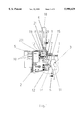
- FIG. 1 shows a section through a housing, for example for a lock subassembly of a central locking system in a motor vehicle,
- FIG. 2 shows a section along the line 2--2 from FIG. 1,
- FIG. 3A is an enlarged view of FIG. 3 showing sealing element 50 and potting compound 51,
- FIG. 3 shows an extract according to detail III from FIG. 1, on an enlarged scale
- FIG. 4 shows the housing as in FIG. 1, but without electric components
- FIG. 5 shows a side view of an electric switch
- FIG. 6 shows a section through the electric switch according to line 6--6 from FIG. 5,
- FIG. 7 illustrates a steering wheel lock in a motor vehicle including a subassembly according to the invention
- FIG. 8 shows an ignition lock in a motor vehicle including a subassembly according to the invention
- FIG. 9 is a representation of a domestic appliance including a subassembly according to the invention.
- FIG. 10 is a schematic illustration of a machine tool including a subassembly according to the invention.
- FIG. 1 shows a subassembly 1 which is designed in the manner of an electrical component carrier and is arranged in a housing 2.
- This subassembly is, for example, a lock subassembly for a central locking system which is employed in the door of a motor vehicle.
- Located in the housing 2 are various mechanical, electric and electronic components which, however, are not further relevant to the actual invention and are therefore not shown in more detail.
- an electric switch 7 located in the interior of the housing 2 being used for establishing the locked or unlocked position of the locking knob.
- the switch 7 is operated in one of the two positions of the locking knob by means of a bevel 6 on an actuating lever 11, which is operatively connected to the locking knob, is indicated only schematically and can be moved according to the arrow 3, so that the switch signal emitted by the switch 7 encodes the corresponding position of the locking knob.
- Located in the interior of the housing 2 is a further electric switch 8.
- This switch 8 is used to interrogate the position in which a rotary latch on the lock of the car door is located.
- the switch 8 is operated by an actuating element 18, which is located outside the housing 2, is operatively connected to the rotary latch and can be moved according to the arrow 4, and which is likewise indicated only schematically in FIG. 1, via an opening 20 made in a housing wall 19 of the housing 2.
- the actuating element 18 acts on the switch 8 via a spring lever 21 which is fastened on the housing 2 and can be seen in more detail in particular in FIG. 2.
- the electrical connection between the switches 7, 8 and the other electrical and electronic components is produced by means of lines 9 in the interior of the housing 2.
- the lines 9 lead further to electric terminals 10 which project out of the housing 2 and, for the purpose of protection, are surrounded by a housing extension 5.
- the terminals 10 are used for the electrical connection of the subassembly 1 to further components of the motor vehicle.
- the electric switches 7, 8 are snap-action or microswitches which are known per se. For example, one design for such a switch can be seen in more detail in section in FIG. 6.
- the switch 7, 8 has its own switch housing 12.
- the contact system 16 Located in the switch housing 12 is the contact system 16, which is electrically connected via terminals 13, for example soldering terminals, to the lines 9 shown in FIG. 1.
- the contact system 16 of the switch 7, 8 is switched by means of an operating member 14 which leads into the switch housing 12 and is designed as a linear plunger which is movable in the direction of arrow 37.
- the switch housing 12 of the switch 7, 8 is preferably designed to be inherently watertight and dust-tight.
- a sealing cap 15 configured in the manner of a bellows is fitted on the switch housing 12 in the region of the operating member 14.
- the sealing cap 15 can be fastened by means of a collar 17 on the switch housing 12, for example by means of rolling.
- a base 39 is inserted into the switch housing 12 on that side opposite the operating member 14, the gap between the base 39 and the switch housing 12 being additionally able to be sealed by means of a potting compound 40.
- the further switch 8 is arranged in the region of the housing wall 19 in the vicinity of the opening 20, to be precise in such a way that the operating member 14 passes through the opening 20 in the housing wall 19.
- the switch 8 rests with a surface 22 of the switch housing 12, which surface is assigned to the operating member 14, directly on at least a part of the surface 23 of the housing wall 19 surrounding the opening 20.
- the surface 22 of the switch housing 12 is formed by a part of the collar 17.
- the surface 23 of the housing wall 19 is the circumferential rim of the opening 20 in the housing wall 19.
- the outer surface of the collar 17 is designed to run obliquely, approximately in the manner of a truncated cone.
- the opening 20 has an approximately circular cross section, which corresponds to the collar 17.
- the opening 20 preferably has a slightly smaller diameter than the largest external diameter of the collar 17, as a result of which the surface 22 rests on the collar with a certain contact pressure on that surface 23 of the housing wall 19 surrounding the opening 20. This achieves particularly good sealing, even though the surface 22 on the collar 17 rests directly on this surface 23 without additional sealing means.
- the surface 23 surrounding the opening 20 can be lengthened with an extension 24, reaching into the interior of the housing 2, on the housing wall 19. This produces an increased sealing surface in the opening 20.
- the extension 24 can additionally rest with its end face 25 on the surface 26 of the switch housing 12, which is approximately perpendicular to the direction of motion of the operating member 14 according to the arrow 37 from FIG. 6.
- a resilient sealing element, 50 to be additionally arranged between the end face 25 and the surface 26.
- the electric switch 8 has retaining pins 28, as can be seen in FIG. 5.
- the switch 8 has two such retaining pins 28.
- the switch 8 is held in the housing 2 by these retaining pins 28 in a retainer 27 shown in more detail in FIG. 4.
- the retainer 27 has latch holders 38 corresponding to the retaining pins 28.
- the latch holder 38 for the retaining pin 28 is preferably designed in each case from two latching or snap-action hooks 29, which are approximately triangular with their tips 32 located opposite one another, and an approximately semicircular stop 33.
- the switch housing 12 is latched in in the correct position in the retainer 27, in that the two retaining pins 28 engage into the respective latch holders 38.
- insertion bevels 31 designed in the manner of ribs 30 are made on the retainer 27 for the switch housing 12.
- the switch housing 12 is then placed onto the insertion bevel 31 such that the operating member 14 passes through the opening 20 in the housing 2.
- the switch 8 subsequently slides, as a result of the action of pressure on the switch housing 12, along the insertion bevel 31, the retaining pin 28, after overcoming a type of pressure point between the tips 32 of the latching or snap-action hooks 29, being fixed in the latch holder 38 by the stop 33 and the two latching or snap-action hooks 29.
- a rim 34 can be made along the retainer 27.
- the switch housing 12 can then be provided with a potting compound 51 within the region which is bounded by the rim 34.
- the potting compound 51 it can also be sufficient for the potting compound 51 to be applied at least in the region of the opening 20 on the retainer 27.
- the opening 27 and the collar 17 on the switch housing 12 are dimensioned in such a way that, on the basis of capillary forces, the potting compound 51 can penetrate into the gap between the housing wall 19 and the collar 17 and can harden there. As a result, the sealing of the opening 20 in the housing 2 with respect to the outside can be still further improved.
- a subassembly may be used in a steering wheel lock (FIG. 7) or an ignition lock (FIG. 8).
- a subassembly in a housing contains a switch which is operated by actuating means located outside the housing, or is to be fixed in the housing in the correct position in a simple way.
- these may be subassemblies for electric domestic appliances (FIG. 9), machine tools (FIG. 10) or the like.
Landscapes
- Engineering & Computer Science (AREA)
- Mechanical Engineering (AREA)
- Lock And Its Accessories (AREA)
- Switch Cases, Indication, And Locking (AREA)
- Push-Button Switches (AREA)
- Mechanisms For Operating Contacts (AREA)
Applications Claiming Priority (2)
| Application Number | Priority Date | Filing Date | Title |
|---|---|---|---|
| DE19616249 | 1996-04-24 | ||
| DE19616249A DE19616249A1 (de) | 1996-04-24 | 1996-04-24 | Baugruppe mit elektrischem Schalter |
Publications (1)
| Publication Number | Publication Date |
|---|---|
| US5990429A true US5990429A (en) | 1999-11-23 |
Family
ID=7792235
Family Applications (1)
| Application Number | Title | Priority Date | Filing Date |
|---|---|---|---|
| US08/844,666 Expired - Fee Related US5990429A (en) | 1996-04-24 | 1997-04-21 | Subassembly with an electric switch |
Country Status (3)
| Country | Link |
|---|---|
| US (1) | US5990429A (de) |
| EP (1) | EP0803405B1 (de) |
| DE (2) | DE19616249A1 (de) |
Cited By (7)
| Publication number | Priority date | Publication date | Assignee | Title |
|---|---|---|---|---|
| US20050248893A1 (en) * | 2004-05-10 | 2005-11-10 | Gary Anderson | Power tool lockdown device |
| US20050247348A1 (en) * | 2004-05-10 | 2005-11-10 | Gary Anderson | Pneumatic tool lock |
| US20060237297A1 (en) * | 2005-04-18 | 2006-10-26 | Xinsheng Xu | Switch assembly |
| US20070163863A1 (en) * | 2006-01-17 | 2007-07-19 | Computerized Security Systems, Inc. | Water resistant keycard reader assembly for an electronic lock |
| US20090219118A1 (en) * | 2004-05-10 | 2009-09-03 | Gary Anderson | Power tool lockdown device |
| US9847194B2 (en) | 2014-03-28 | 2017-12-19 | Black & Decker Inc. | Integrated electronic switch and control module for a power tool |
| US10541588B2 (en) | 2017-05-24 | 2020-01-21 | Black & Decker Inc. | Electronic power module for a power tool having an integrated heat sink |
Families Citing this family (2)
| Publication number | Priority date | Publication date | Assignee | Title |
|---|---|---|---|---|
| DE102006035341A1 (de) * | 2006-10-12 | 2008-04-17 | Hilti Ag | Handwerkzeugmaschine |
| CN107499259B (zh) * | 2017-09-20 | 2024-04-16 | 中国重汽集团济南动力有限公司 | 一种多轴轮驱电动汽车用分布式控制电配电系统 |
Citations (11)
| Publication number | Priority date | Publication date | Assignee | Title |
|---|---|---|---|---|
| US2814703A (en) * | 1955-07-18 | 1957-11-26 | Honeywell Regulator Co | Sealed switch |
| US2950373A (en) * | 1958-12-02 | 1960-08-23 | Controls Co Of America | Device for rendering electric switches environment-resistant |
| US3231706A (en) * | 1961-07-24 | 1966-01-25 | Cutler Hammer Inc | Illuminated pushbutton switches having tanden lamp impedance devices |
| US3940585A (en) * | 1974-05-13 | 1976-02-24 | Indak Manufacturing Corporation | Heavy duty push-button electrical switch |
| US4342894A (en) * | 1980-10-06 | 1982-08-03 | Robertshaw Controls Company | Electrical switch construction diaphragm seal therefor and methods of making the same |
| US4788387A (en) * | 1985-10-30 | 1988-11-29 | Omron Tateisi Electronics Co. | Limit switch with curved or partly spherical convex cover |
| DE8904332U1 (de) * | 1989-04-07 | 1989-06-22 | Marquardt GmbH, 7207 Rietheim-Weilheim | Elektrischer Schalter |
| DE4015587A1 (de) * | 1989-05-16 | 1990-11-29 | Tokai Rika Co Ltd | Schaltervorrichtung fuer motorbetriebene verstellbare fahrzeugsitze |
| DE9105624U1 (de) * | 1990-05-25 | 1991-07-04 | Bomoro Bocklenberg & Motte Gmbh & Co Kg, 42369 Wuppertal | Kraftfahrzeug-Türschloß, -Haubenschloß o.dgl. |
| EP0536056A1 (de) * | 1991-10-04 | 1993-04-07 | Automobiles Peugeot | Ladesteckdose für motorisiertes Elektrofahrzeug |
| DE29510010U1 (de) * | 1995-06-20 | 1995-11-16 | Siemens AG, 80333 München | Betätigungselement für einen im Inneren eines Kommunikationsendgerätes angeordneten Schalter |
Family Cites Families (5)
| Publication number | Priority date | Publication date | Assignee | Title |
|---|---|---|---|---|
| DE4221458A1 (de) * | 1992-06-30 | 1994-01-05 | Priesemuth W | Schalteinrichtung |
| DE9213371U1 (de) * | 1992-10-05 | 1994-02-10 | Barlian, Reinhold, Dipl.-Ing. (FH), 97980 Bad Mergentheim | Schalteinrichtung |
| DE9406697U1 (de) * | 1994-04-22 | 1994-11-03 | MENTOR GmbH & Co Präzisions-Bauteile, 40699 Erkrath | Funktionseinheit zum Schalten, Steuern und Anzeigen von Vorgängen in Automobilen |
| DE4430700A1 (de) * | 1994-08-30 | 1996-03-07 | Teves Gmbh Alfred | In Motordeckel integrierter Schalter |
| DE4442971C1 (de) * | 1994-12-02 | 1996-01-04 | Hella Kg Hueck & Co | Geschwindigkeitsregler für ein Kraftfahrzeug |
-
1996
- 1996-04-24 DE DE19616249A patent/DE19616249A1/de not_active Withdrawn
-
1997
- 1997-04-12 DE DE59707543T patent/DE59707543D1/de not_active Expired - Lifetime
- 1997-04-12 EP EP97106035A patent/EP0803405B1/de not_active Expired - Lifetime
- 1997-04-21 US US08/844,666 patent/US5990429A/en not_active Expired - Fee Related
Patent Citations (11)
| Publication number | Priority date | Publication date | Assignee | Title |
|---|---|---|---|---|
| US2814703A (en) * | 1955-07-18 | 1957-11-26 | Honeywell Regulator Co | Sealed switch |
| US2950373A (en) * | 1958-12-02 | 1960-08-23 | Controls Co Of America | Device for rendering electric switches environment-resistant |
| US3231706A (en) * | 1961-07-24 | 1966-01-25 | Cutler Hammer Inc | Illuminated pushbutton switches having tanden lamp impedance devices |
| US3940585A (en) * | 1974-05-13 | 1976-02-24 | Indak Manufacturing Corporation | Heavy duty push-button electrical switch |
| US4342894A (en) * | 1980-10-06 | 1982-08-03 | Robertshaw Controls Company | Electrical switch construction diaphragm seal therefor and methods of making the same |
| US4788387A (en) * | 1985-10-30 | 1988-11-29 | Omron Tateisi Electronics Co. | Limit switch with curved or partly spherical convex cover |
| DE8904332U1 (de) * | 1989-04-07 | 1989-06-22 | Marquardt GmbH, 7207 Rietheim-Weilheim | Elektrischer Schalter |
| DE4015587A1 (de) * | 1989-05-16 | 1990-11-29 | Tokai Rika Co Ltd | Schaltervorrichtung fuer motorbetriebene verstellbare fahrzeugsitze |
| DE9105624U1 (de) * | 1990-05-25 | 1991-07-04 | Bomoro Bocklenberg & Motte Gmbh & Co Kg, 42369 Wuppertal | Kraftfahrzeug-Türschloß, -Haubenschloß o.dgl. |
| EP0536056A1 (de) * | 1991-10-04 | 1993-04-07 | Automobiles Peugeot | Ladesteckdose für motorisiertes Elektrofahrzeug |
| DE29510010U1 (de) * | 1995-06-20 | 1995-11-16 | Siemens AG, 80333 München | Betätigungselement für einen im Inneren eines Kommunikationsendgerätes angeordneten Schalter |
Cited By (14)
| Publication number | Priority date | Publication date | Assignee | Title |
|---|---|---|---|---|
| US20090219118A1 (en) * | 2004-05-10 | 2009-09-03 | Gary Anderson | Power tool lockdown device |
| US20050247348A1 (en) * | 2004-05-10 | 2005-11-10 | Gary Anderson | Pneumatic tool lock |
| US7007712B2 (en) | 2004-05-10 | 2006-03-07 | Gary Anderson | Pneumatic tool lock |
| US20050248893A1 (en) * | 2004-05-10 | 2005-11-10 | Gary Anderson | Power tool lockdown device |
| US7750509B2 (en) | 2004-05-10 | 2010-07-06 | Gary Anderson | Power tool lockdown device |
| US7317263B2 (en) | 2004-05-10 | 2008-01-08 | Gary Anderson | Power tool lockdown device |
| US20060237297A1 (en) * | 2005-04-18 | 2006-10-26 | Xinsheng Xu | Switch assembly |
| US7705260B2 (en) | 2005-04-18 | 2010-04-27 | Xinsheng Xu | Switch assembly |
| US8330066B2 (en) | 2005-04-18 | 2012-12-11 | Shanghai Bai Cheng Electric Equipment | Switch assembly |
| US20070163863A1 (en) * | 2006-01-17 | 2007-07-19 | Computerized Security Systems, Inc. | Water resistant keycard reader assembly for an electronic lock |
| US9847194B2 (en) | 2014-03-28 | 2017-12-19 | Black & Decker Inc. | Integrated electronic switch and control module for a power tool |
| US10043619B2 (en) | 2014-03-28 | 2018-08-07 | Black & Decker Inc. | Biasing member for a power tool forward/reverse actuator |
| US10497524B2 (en) | 2014-03-28 | 2019-12-03 | Black & Decker Inc. | Integrated electronic switch and control module for a power tool |
| US10541588B2 (en) | 2017-05-24 | 2020-01-21 | Black & Decker Inc. | Electronic power module for a power tool having an integrated heat sink |
Also Published As
| Publication number | Publication date |
|---|---|
| EP0803405A3 (de) | 1998-08-26 |
| DE19616249A1 (de) | 1997-10-30 |
| EP0803405B1 (de) | 2002-06-19 |
| DE59707543D1 (de) | 2002-07-25 |
| EP0803405A2 (de) | 1997-10-29 |
Similar Documents
| Publication | Publication Date | Title |
|---|---|---|
| KR100186787B1 (ko) | 차량 도어 잠금장치용 액츄에이터 | |
| US5990429A (en) | Subassembly with an electric switch | |
| US20080034821A1 (en) | Latch-release actuating apparatus | |
| US5284448A (en) | Electrical device, in particular a switching and control unit for motor vehicles | |
| US6180905B1 (en) | Two position pushbutton switch with illuminated button | |
| US5952731A (en) | Membrane keyless entry switch for vehicles | |
| US4805233A (en) | Anti-theft arrangement for a sound-reproducing apparatus installed into a mounting compartment of a motor vehicle | |
| JPS6356658B2 (de) | ||
| US5162625A (en) | Switch assembly | |
| US3204069A (en) | Door switch assembly | |
| CA1297142C (en) | Housing including a test button secured thereto with a living hinge | |
| US5360351A (en) | Housing for the interface between a motor vehicle lock, its actuator and the electrical connection harness of the vehicle | |
| GB2186118A (en) | Pressure switch | |
| US6025564A (en) | Single stalk steering column switch | |
| KR20010040443A (ko) | 자동차의 조향 칼럼 기어 스위치용 스틱 시프트 | |
| US6150620A (en) | Steering column switch for a motor vehicle | |
| EP0393595B1 (de) | Elektrische Schliessvorrichtung, insbesondere für Haube oder Deckel von Kraftfahrzeugen | |
| US6445081B1 (en) | Locking arrangement, in particular for vehicles | |
| US8178807B2 (en) | Electrical switch | |
| JP2000182472A (ja) | 車両用操作レバー | |
| US20010035335A1 (en) | Switch subassembly and component assemblies including such a switch subassembly | |
| JP3805915B2 (ja) | 多方向入力装置 | |
| JPH0528657Y2 (de) | ||
| EP0566230A1 (de) | Verschlusssystem für ein Kraftfahrzeug | |
| JPH10269899A (ja) | コンビネーションスイッチ |
Legal Events
| Date | Code | Title | Description |
|---|---|---|---|
| AS | Assignment |
Owner name: MARQUARDT GMBH, GERMANY Free format text: ASSIGNMENT OF ASSIGNORS INTEREST;ASSIGNOR:KRAMER, MARKUS;REEL/FRAME:008524/0428 Effective date: 19970324 |
|
| FEPP | Fee payment procedure |
Free format text: PAYOR NUMBER ASSIGNED (ORIGINAL EVENT CODE: ASPN); ENTITY STATUS OF PATENT OWNER: LARGE ENTITY |
|
| FEPP | Fee payment procedure |
Free format text: PAYER NUMBER DE-ASSIGNED (ORIGINAL EVENT CODE: RMPN); ENTITY STATUS OF PATENT OWNER: LARGE ENTITY Free format text: PAYOR NUMBER ASSIGNED (ORIGINAL EVENT CODE: ASPN); ENTITY STATUS OF PATENT OWNER: LARGE ENTITY |
|
| FPAY | Fee payment |
Year of fee payment: 4 |
|
| FPAY | Fee payment |
Year of fee payment: 8 |
|
| REMI | Maintenance fee reminder mailed | ||
| LAPS | Lapse for failure to pay maintenance fees | ||
| STCH | Information on status: patent discontinuation |
Free format text: PATENT EXPIRED DUE TO NONPAYMENT OF MAINTENANCE FEES UNDER 37 CFR 1.362 |
|
| FP | Lapsed due to failure to pay maintenance fee |
Effective date: 20111123 |