US5991074A - Stereoscopic image display apparatus - Google Patents
Stereoscopic image display apparatus Download PDFInfo
- Publication number
- US5991074A US5991074A US09/015,345 US1534598A US5991074A US 5991074 A US5991074 A US 5991074A US 1534598 A US1534598 A US 1534598A US 5991074 A US5991074 A US 5991074A
- Authority
- US
- United States
- Prior art keywords
- polarizing
- stripe
- display unit
- images
- observer
- Prior art date
- Legal status (The legal status is an assumption and is not a legal conclusion. Google has not performed a legal analysis and makes no representation as to the accuracy of the status listed.)
- Expired - Lifetime
Links
Images




Classifications
-
- G—PHYSICS
- G02—OPTICS
- G02B—OPTICAL ELEMENTS, SYSTEMS OR APPARATUS
- G02B30/00—Optical systems or apparatus for producing three-dimensional [3D] effects, e.g. stereoscopic images
- G02B30/20—Optical systems or apparatus for producing three-dimensional [3D] effects, e.g. stereoscopic images by providing first and second parallax images to an observer's left and right eyes
- G02B30/22—Optical systems or apparatus for producing three-dimensional [3D] effects, e.g. stereoscopic images by providing first and second parallax images to an observer's left and right eyes of the stereoscopic type
- G02B30/25—Optical systems or apparatus for producing three-dimensional [3D] effects, e.g. stereoscopic images by providing first and second parallax images to an observer's left and right eyes of the stereoscopic type using polarisation techniques
-
- H—ELECTRICITY
- H04—ELECTRIC COMMUNICATION TECHNIQUE
- H04N—PICTORIAL COMMUNICATION, e.g. TELEVISION
- H04N13/00—Stereoscopic video systems; Multi-view video systems; Details thereof
- H04N13/30—Image reproducers
- H04N13/332—Displays for viewing with the aid of special glasses or head-mounted displays [HMD]
- H04N13/337—Displays for viewing with the aid of special glasses or head-mounted displays [HMD] using polarisation multiplexing
-
- H—ELECTRICITY
- H04—ELECTRIC COMMUNICATION TECHNIQUE
- H04N—PICTORIAL COMMUNICATION, e.g. TELEVISION
- H04N13/00—Stereoscopic video systems; Multi-view video systems; Details thereof
- H04N13/30—Image reproducers
- H04N13/398—Synchronisation thereof; Control thereof
-
- H—ELECTRICITY
- H04—ELECTRIC COMMUNICATION TECHNIQUE
- H04N—PICTORIAL COMMUNICATION, e.g. TELEVISION
- H04N13/00—Stereoscopic video systems; Multi-view video systems; Details thereof
- H04N13/10—Processing, recording or transmission of stereoscopic or multi-view image signals
-
- H—ELECTRICITY
- H04—ELECTRIC COMMUNICATION TECHNIQUE
- H04N—PICTORIAL COMMUNICATION, e.g. TELEVISION
- H04N13/00—Stereoscopic video systems; Multi-view video systems; Details thereof
- H04N13/20—Image signal generators
- H04N13/204—Image signal generators using stereoscopic image cameras
- H04N13/239—Image signal generators using stereoscopic image cameras using two two-dimensional [2D] image sensors having a relative position equal to or related to the interocular distance
-
- H—ELECTRICITY
- H04—ELECTRIC COMMUNICATION TECHNIQUE
- H04N—PICTORIAL COMMUNICATION, e.g. TELEVISION
- H04N13/00—Stereoscopic video systems; Multi-view video systems; Details thereof
- H04N13/20—Image signal generators
- H04N13/286—Image signal generators having separate monoscopic and stereoscopic modes
-
- H—ELECTRICITY
- H04—ELECTRIC COMMUNICATION TECHNIQUE
- H04N—PICTORIAL COMMUNICATION, e.g. TELEVISION
- H04N13/00—Stereoscopic video systems; Multi-view video systems; Details thereof
- H04N13/30—Image reproducers
- H04N13/302—Image reproducers for viewing without the aid of special glasses, i.e. using autostereoscopic displays
- H04N13/305—Image reproducers for viewing without the aid of special glasses, i.e. using autostereoscopic displays using lenticular lenses, e.g. arrangements of cylindrical lenses
-
- H—ELECTRICITY
- H04—ELECTRIC COMMUNICATION TECHNIQUE
- H04N—PICTORIAL COMMUNICATION, e.g. TELEVISION
- H04N13/00—Stereoscopic video systems; Multi-view video systems; Details thereof
- H04N13/30—Image reproducers
- H04N13/302—Image reproducers for viewing without the aid of special glasses, i.e. using autostereoscopic displays
- H04N13/31—Image reproducers for viewing without the aid of special glasses, i.e. using autostereoscopic displays using parallax barriers
-
- H—ELECTRICITY
- H04—ELECTRIC COMMUNICATION TECHNIQUE
- H04N—PICTORIAL COMMUNICATION, e.g. TELEVISION
- H04N13/00—Stereoscopic video systems; Multi-view video systems; Details thereof
- H04N13/30—Image reproducers
- H04N13/361—Reproducing mixed stereoscopic images; Reproducing mixed monoscopic and stereoscopic images, e.g. a stereoscopic image overlay window on a monoscopic image background
-
- H—ELECTRICITY
- H04—ELECTRIC COMMUNICATION TECHNIQUE
- H04N—PICTORIAL COMMUNICATION, e.g. TELEVISION
- H04N13/00—Stereoscopic video systems; Multi-view video systems; Details thereof
- H04N13/30—Image reproducers
- H04N13/363—Image reproducers using image projection screens
Definitions
- the present invention relates to a stereoscopic image display apparatus, and more particularly to such apparatus adapted for stereoscopic display of image information by a display device such as a television, a video display, a computer monitor, a game machine or the like and for stereoscopic observation of the image information from a predetermined observation area.
- a display device such as a television, a video display, a computer monitor, a game machine or the like and for stereoscopic observation of the image information from a predetermined observation area.
- the polarized state of light is made different from the image for the left eye and that for the right eye and the left and right images are separated by the polarization spectacles.
- a liquid crystal shutter is provided on the display to switch the polarizing state in synchronization with the field signal of the displayed image, while the observer utilizes the polarization spectacles whereby the left and right images are separated to the respective eyes on time-shared basis to enable stereoscopic observation.
- the field frequency has to be selected as about 90 to 120 Hz in order to avoid flickering phenomenon. For this reason there is required a display with a high scanning frequency, and the display currently applicable for this purpose is limited to the CRT or the projection display utilizing the CRT.
- FIG. 1 there are shown a notebook-shaped personal computer 101 serving as a stereoscopic image display apparatus, and a stereoscopic display 102 composed of a liquid crystal display provided, on the image display surface thereof, with a polarization control plate 4 in which two polarizing plates 4L, 4R with mutually perpendicular polarizing states are arranged in horizontal stripes.
- the polarization spectacles 103 are not used, and each of the left and right eyes of the observer observes all the pixels of the liquid display 102 without recognizing the difference in the polarized state, so that the observer can observe the image as in the ordinary two-dimensional display.
- the observer uses the polarization spectacles 103 in which the polarizing directions of the left and right eyes are mutually perpendicular, so that the left and right eyes respectively observe the pixels of different polarizing directions.
- the stereoscopic observation is made possible by displaying, on the liquid crystal display 102, left and right parallax images corresponding to the polarizing directions of the polarizing plates 4L, 4R in the horizontal stripes of the polarization control plate 4.
- FIGS. 2A and 2B are schematic perspective views showing the configuration of a conventional stereoscopic display, wherein a liquid crystal display 1 is composed of glass substrates 2 (2a, 2b) and a pixel display unit 3 provided therebetween and consisting of liquid crystal, electrodes etc.
- a liquid crystal display 1 is composed of glass substrates 2 (2a, 2b) and a pixel display unit 3 provided therebetween and consisting of liquid crystal, electrodes etc.
- a liquid crystal display 1 is composed of glass substrates 2 (2a, 2b) and a pixel display unit 3 provided therebetween and consisting of liquid crystal, electrodes etc.
- two polarizing plates having mutually orthogonal polarizing directions and positioned respective in front of the front glass substrate 2a and behind the rear glass substrate 2b, and a rear light source positioned behind the glass substrates.
- a polarization control plate 4 On the surface of the glass substrate 2a of the observation side, there is provided a polarization control plate 4, in which polarizing plates 4L, 4R, having the polarizing directions indicated by arrows, are arranged in horizontal stripes.
- polarizing plates 4L, 4R having the polarizing directions indicated by arrows, are arranged in horizontal stripes.
- Such plate can be fabricated for example by mechanical cutting or by photolithography.
- FIG. 2B for explaining the relationship of the polarizing directions between the polarizing plates of the liquid crystal display 1 and the polarization control plate 4.
- the polarizing plates 111, 112 positioned respectively in front of and behind the glass substrates sandwiching the pixel display unit 3 with the liquid crystal are so provided as to have polarizing directions which are inclined by 45° and are mutually perpendicular, in so-called Cross Nicole state.
- the TN normally white mode white and black are respectively displayed when a voltage is applied and not applied to the liquid crystal.
- the light transmitted by the liquid crystal display is polarized in a direction of 45° while the polarizing plates constituting the polarization control plate 4 have the horizontal and vertical polarizing directions as shown in FIG. 2B, there are only transmitted polarized components in such directions. If all the pixels of the pixel display unit 3 display white, the amounts of light transmitted by the respective polarizing plates are mutually same and, without the polarizion spectacles, all the pixels can be observed as a two-dimensional image, as in the ordinary liquid crystal display.
- the pitch of the horizontal stripes constituted by the polarizing plates 4L, 4R of the polarization control plate 4 is selected equal to or slightly smaller than the width of a pixel row (L, R) corresponding to a scanning line of the pixel display unit 3 of the liquid crystal display 1.
- the pixel display unit 3 displays the left-eye image L and the right-eye image R alternately in every scanning line, in such a manner that the left-eye image L corresponds to a stripe of the polarizing plate 4L with the vertical polarizing direction and the right-eye image R corresponds to a stripe of the polarizing plate 4R with the horizontal polarizing direction.
- the observer uses the polarization spectacles in which the left eye has a polarizing plate 4L with the vertical polarizing direction and the right eye has a polarizing plate 4R with the horizontal polarizing direction. Since each polarizing plate intercepts the polarized light of the perpendicular polarized direction, the left-eye image L and the right-eye image R are separated and observed respectively by the left and right eyes.
- FIG. 3 is a lateral cross-sectional view of the stereoscopic display shown in FIGS. 2A and 2B.
- the pixel display unit 3 of the liquid crystal display 1 is composed of a black matrix 10, separating the pixels in the vertical direction, and pixel apertures 11, which are so provided that the polarizing plates 4L, 4R in the horizontal stripes of the polarization control plate 4 are positioned on the line between the eye 12 of the observer wearing the polarization spectacles 13 and each pixel aperture 11.
- the polarization control plate 4 can be positioned directly on the pixel display unit 3 of the liquid crystal display 1, there will not occur mutual aberration between the displayed pixels and the polarizing plates 4L, 4R regardless of the position of the observer.
- the glass substrate of the liquid crystal display has a certain thickness and the polarization control plate 4 cannot be positioned closer thereto.
- the pixel display unit 3 becomes displaced with respect to the polarizing plates 4L, 4R so that the left and right images L, R cannot be satisfactorily separated and the stereoscopic observation cannot be obtained at a certain height of the eyes 12 of the observer.
- the polarizing plates 4L, 4R appear completely superposed with the pixel apertures 11, so that the left-eye image L and the right-eye image R are completely separated and a normal stereoscopic image can be observed.
- the line connecting the pixel aperture 11 and the eyes 12 rides on the vertically adjacent polarizing plates of horizontal stripe shape on the polarization control plate 4, so that the light emerging from a same pixel aperture 11 contains mutually perpendicular polarized components.
- the light emerging from the same pixel aperture 11 completely passes through the adjacent polarized plate and horizontal stripe shape of the perpendicular polarizing direction, whereby the left eye only receives the right-eye image R while the right eye only receives the left-eye image L to realize a state of inverse stereoscopic observation.
- a graph at the left-hand side of FIG. 3 indicates the change in the amount of polarized component, wherein the abscissa indicates the proportion of the polarized light component entering either eye, or the amount of crosstalk.
- the proportion is defined as 0.5 or a state of half crosstalk.
- the proportion of the polarized component gradually decreases with the corresponding increase of crosstalk, and reaches 0 at the position a2 or a3 where the state of completely inverse stereoscopic observation is reached.
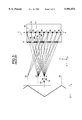
- FIG. 4 shows the stereoscopic observation areas at the optimum observation distance for the stereoscopic display 201 of the above-explained configuration, wherein 202 indicates areas (represented by solid lines) allowing normal stereoscopic observation while 203 indicates areas (represented by broken lines) providing inverse stereoscopic observation, and these areas appear periodically in the vertical direction V.
- the eye height allowing stereoscopic observation without crosstalk is limited to the line a1, and the stereoscopic observation area is practically limited in the vertical direction because of the generation of the crosstalk.
- observation height limits the viewing position, thereby rendering the observation with plural persons quite difficult.
- a first object of the present invention is to provide a stereoscopic image display apparatus which displays the three-dimensional image utilizing a polarization control plate and is capable of expanding the stereoscopic observation area with limited crosstalk in the vertical direction by means of a barrier having an aperture elongated in a suitable predetermined direction or a lenticular lens, thereby reducing the fatigue of the observer and facilitating the stereoscopic observation by plural observers.
- FIG. 1 is a schematic perspective view of a conventional stereoscopic viewing system
- FIGS. 2A and 2B are respectively a schematic perspective view of a conventional configuration and a schematic view showing the polarizing directions of the polarizing plates;
- FIG. 3 is a lateral cross-sectional view of the system shown in FIG. 1;
- FIG. 4 is a view showing the stereoscopic viewing areas in the system shown in FIG. 1;
- FIG. 5 is a schematic perspective view showing the configuration of an embodiment 1 of the present invention.
- FIG. 6 is a lateral cross-sectional of the embodiment 1 of the present invention.
- FIG. 7 is a view showing the stereoscopic viewing area of the embodiment 1 of the present invention.
- FIG. 8 is a schematic perspective view showing the configuration of an embodiment 2 of the present invention.
- FIG. 9 is a lateral cross-sectional of the embodiment 2 of the present invention.
- FIG. 10 is a view showing the stereoscopic viewing area of the embodiment 2 of the present invention.
- FIG. 11 is a schematic perspective view showing the configuration of an embodiment 3 of the present invention.
- FIG. 12 is a lateral cross-sectional of the embodiment 3 of the present invention.
- FIG. 13 is a view showing the stereoscopic viewing area of the embodiment 3 of the present invention.
- FIG. 5 is a schematic perspective view of an embodiment 1 of the present invention.
- FIG. 6 is a view showing the principle of stereoscopic observation of the embodiment shown in FIG. 5.
- FIG. 7 is a view showing an area allowing stereoscopic observation in the embodiment shown in FIG. 5.
- FIG. 5 there is shown a liquid crystal display (LCD) 1 for image display, provided therein with a pixel display unit 3, glass substrates 2a, 2b respectively provided in front of and behind the pixel display unit 3, polarizing plates (not shown) having mutually orthogonal polarizing directions and provided respective in front of the glass substrate 2a and behind the glass substrate 2b, electrodes (not shown), a rear light source (light source means) 21 etc.
- LCD liquid crystal display
- a display drive circuit 22 displays the images synthesized in horizontal stripes, on the display 1.
- An image processing circuit 23 extracts a plurality of parallax images L, R in horizontal stripes from a set of parallax images obtained by observing a three-dimensional object from two viewing points, and combines thus extracted images by arranging these images with a predetermined order and a predetermined pitch in the vertical direction V thereby obtaining a combined horizontal stripe image for supply to the display drive circuit 22.
- a polarization control plate 4 is composed of a repeated array, with a predetermined pitch in the vertical direction, of two polarizing plates 4L, 4R of a horizontal stripe shape, respectively transmitting polarized lights of mutually orthogonal directions.
- Such polarizing plates 4L, 4R of horizontal stripe shape respectively correspond to the horizontal striped parallax images L, R on the pixel display unit 3.
- a barrier 5 is provided with apertures 6a of a horizontal stripe shape, with a width narrower than the pitch of the polarizing plate of the polarization control plate 4, and with light shielding portions 6b.
- the barrier 5 is formed by forming a film of chromium or chromium oxide on a glass substrate and patterning such film, or by coating the glass substrate wit black resin and patterning such black resin layer.
- FIG. 6 for explaining the state of stereoscopic observation of the parallax images displayed on the pixel display unit 3 of the present embodiment.
- the polarizing plates 4L, 4R in horizontal stripes of the polarization control plate 4 are positioned on the line between the eyes 12 of the observer wearing the polarization spectacles 13 and the pixel apertures 11 where the parallax images L, R are displayed on the pixel display unit 3 of the liquid crystal display 1.
- the barrier 6 is provided in front of the polarization control plate 4, in such a manner that the apertures 6a of the barrier 5 respectively correspond to the polarizing plates 4L, 4R of the polarization control plate 4 and are on the lines between the eyes 12 of the observer and the centers of the pixel apertures 11 displaying the parallax images.
- the observer When the eyes 12 of the observer lie in a vertical position b1, the observer observes a part (width w) of the pixel apertures 11 of the pixel display unit 3, through the apertures 6a of the barrier 5 and the corresponding polarizing plates 4L, 4R.
- the left-eye image L and the right-eye image R are completely separated by the polarization spectacles 13 whereby the normal stereoscopic observation can be attained.
- the observed width w of the pixel display unit 3 rides on the black matrix 10 whereby the amount of light gradually decreases, and the observed width moves to the adjacent pixel aperture 11.
- the adjacent pixel aperture 11 displays the parallax image for the other eye, which is also observed through the same polarizing plate, whereby the crosstalk gradually increases.
- a graph at the left-hand side of FIG. 6 shows the change in the polarized component, wherein abscissa indicates the proportion of the polarized component of light entering either eye or the amount of crosstalk.
- FIG. 7 shows the actual stereoscopic observation areas of the present embodiment, indicating the stereoscopic observation area in the stereoscopic display 301 of the present embodiment, at the optimum observation distance.
- 302 indicates a normal stereoscopic observation area where proper stereoscopic image can be observed.
- 303 indicates inverse stereoscopic observation areas which appear periodically in the vertical direction.
- the stereoscopic observation area enabling stereoscopic observation without crosstalk in the vertical direction is expanded, from a mere linear area in the conventional stereoscopic display, to a certain width in the present embodiment, whereby the observer is assured of satisfactory stereoscopic observation without paying too much attention to the vertical position and is therefore relieved from fatigue.
- the barrier 5 is positioned in front of the polarization control plate 4, but it may also be positioned behind the polarization control plate 4, namely at the side of the display 1 thereof. Also barrier portions may be provided between the polarizing plates constituting the polarization control plate 4.
- a polarization control plate composed of an array of polarizing plates of different polarizing states is provided in front of the display, and, for the observation with the polarization spectacles, there is employed a barrier with plural apertures is combined with the polarization control plate.
- the polarization control plate is composed of an alternate array of the polarizing plates of mutually orthogonal polarizing directions in horizontal stripes, and that the barrier is provided with apertures in horizontal stripe shapes corresponding to the pitch of the horizontal stripes of the polarization control plate, the width of such apertures being smaller than the pitch of the horizontal stripes of the polarization control plate.
- This embodiment is only different from the embodiment 1 in that the barrier 5 is positioned between the polarization control plate 4 and the liquid crystal display 1 but is same in all other aspects.
- FIG. 9 for explaining the state of stereoscopic observation of the parallax images displayed on the pixel display unit 3 of the present embodiment.
- the polarizing plates 4L, 4R in horizontal stripes of the polarization control plate 4 are positioned on the line between the eyes 12 of the observer wearing the polarization spectacles 13 and the pixel apertures 11 where the parallax images L, R are displayed on the pixel display unit 3 of the liquid crystal display 1.
- the apertures 6a of the barrier 5 are positioned on the lines between the eyes 12 of the observer and the centers of the pixel apertures 11 displaying the parallax images, whereby the observer observes the corresponding pixel apertures 11 through the polarizing plates and the apertures 6a of the barrier 5.
- the observer When the eyes 12 of the observer lie in a vertical position c1, the observer observes, in superposed manner, the polarizing plates and a part (width W) of the pixel apertures 11 of the pixel display unit 3, through the apertures 6a of the barrier 5.
- the left-eye image L and the right-eye image R are completely separated by the polarization spectacles 13 whereby the normal stereoscopic observation can be attained.
- the line between the aperture 6a of the barrier 5 and the eyes of the observer is shifted from the center of the pixel aperture, but, as long as the observed width W does not still reach the black matrix 10, a part of the same pixel aperture 11 is still observed. If the position of the barrier 5 is so selected that the line between the aperture 6a of the barrier 5 and the eyes of the observer moves within the same corresponding polarizing plate 4, the left-eye image L and the right-eye image R can be completely separated to enable normal stereoscopic observation as in the eye position c1.
- the observed width W of the pixel display unit 3 rides on the black matrix 10 whereby the amount of light gradually decreases and the crosstalk is generated. With further movement, the observed width moves to the adjacent pixel aperture 11 and the corresponding polarizing plate is switched to the adjacent one, but, at a position c2, the normal stereoscopic observation is made possible as the combination between the left and right images L, R and the polarizing directions of the polarizing plates remains same.
- a graph at the left-hand side of FIG. 9 shows the change in the polarized component, wherein abscissa indicates the proportion of the polarized component of light entering either eye or the amount of crosstalk.
- FIG. 10 shows the actual stereoscopic observation areas of the present embodiment, indicating the stereoscopic observation area in the stereoscopic display 401 of the present embodiment, at the optimum observation distance.
- 402 indicates normal stereoscopic observation areas which appear periodically in the vertical direction, and there is no inverse stereoscopic observation area.
- the stereoscopic observation area enabling stereoscopic observation without crosstalk in the vertical direction is further expanded, whereby the observer is assured of satisfactory stereoscopic observation without paying too much attention to the vertical position and is therefore relieved from fatigue.
- FIG. 11 is a schematic perspective view of an embodiment 3 of the present invention
- FIG. 12 is a view showing the principle of stereoscopic observation of the embodiment shown in FIG. 11
- FIG. 13 is a view showing an area allowing stereoscopic observation in the embodiment shown in FIG. 11.
- This embodiment is only different from the embodiment 2 shown in FIG. 8 in that the barrier 5 is replaced by a lenticular lens 7 which is composed of an array, with a predetermined pitch in the vertical direction V, of cylindrical lenses 7a of a horizontal stripe shape having a refractive power in the vertical direction V, but is same in all other aspects.
- the lenticular lens 7 is positioned between the polarization control plate 4 and the liquid crystal display 1.
- the cylindrical lenses 7a constituting the lenticular lens 7 are arrayed horizontally, with a pitch corresponding to that of the polarizing plates 4L, 4R in horizontal stripes of the polarization control plate 4.
- the lenticular lens 7 is prepared by molding a resinous material such as acrylic resin or polycarbonate, or by replica formation with photosensitive resin on a glass substrate.
- FIG. 12 for explaining the state of stereoscopic observation of the parallax images displayed on the pixel display unit 3 of the present embodiment.
- the polarizing plates 4L, 4R in horizontal stripes of the polarization control plate 4 are positioned on the line between the eyes 12 of the observer wearing the polarization spectacles 13 and the pixel apertures 11 where the parallax images L, R are displayed on the pixel display unit 3 of the liquid crystal display 1.
- the cylindrical lenses 7a of the lenticular lens 7 are positioned on the lines between the eyes 12 of the observer and the centers of the pixel apertures 11, whereby the observer observes the corresponding pixel apertures 11 through the polarizing plates 4L, 4R and the cylindrical lenses 7a.
- the position of the lenticular lens 7 and the curvature of the cylindrical lenses 7a thereof are so designed as to focus the image of the pixel display unit 3 on the polarizing plates 4 with such a magnification that the pitch of the pixel display unit 3 coincides with that of the polarizing plates 4L, 4R.
- the eyes 12 of the observer When the eyes 12 of the observer are in a vertical position d1, the lights coming from the pixel apertures 11 of the pixel display unit 3 on the lines passing through the eyes 12 of the observer and the principal points 0 of the cylindrical lenses 7a of the lenticular lens 7 are focused on the polarizing plates 4L, 4R and the observer observes a part of the lights spreading therefrom. Since, in this state, the images of the pixel apertures 11 are formed in complete one-to-one correspondence on the polarizing plates 4L, 4R, the left-eye image L and the right-eye image R are completely separated by the polarization spectacles 13 whereby the normal stereoscopic observation can be attained.
- the eyes 12 of the observer moves in the vertical direction V to a position d4
- the lines passing through the eyes 12 and the principal points of the cylindrical lenses 7a lie on the black matrix 10 of the pixel display unit 3, but the lights from the pixel apertures 11 are focused on the polarizing plates 4L, 4R and are spread after passing the polarizing plates, whereby the eyes 12 of the observer can receive the lights from the adjacent pixel apertures.
- a graph at the left-hand side of FIG. 12 shows the change in the polarized component, wherein abscissa indicates the proportion of the polarized component of light entering either eye or the amount of crosstalk. It is indicated that the proportion of the polarized components always remains as 1 regardless of the position of the eyes of the observer, whereby the left and right images are always completely separated to enable the normal stereoscopic observation.
- FIG. 13 shows the actual stereoscopic observation areas of the present embodiment, indicating the stereoscopic observation area in the stereoscopic display 501 of the present embodiment, at the optimum observation distance.
- 502 indicate normal stereoscopic observation areas, and there is no inverse stereoscopic observation area.
- the normal stereoscopic observation area is represented by a rectangle for the purpose of simplicity, but in fact it is spread over the plane of the rectangle.
- the stereoscopic observation area enabling stereoscopic observation without crosstalk in the vertical direction is further expanded, whereby the observer is assured of satisfactory stereoscopic observation without paying attention to the vertical position and is therefore relieved from fatigue.
- the lenticular lens may be replaced by biconvex or plano-convex cylindrical microlenses.
- a polarization control plate composed of an array of polarizing plates of different polarizing states is provided in front of the display, and, for the observation with the polarization spectacles, there is employed a microlens array composed of cylindrical lenses between the polarization control plate and the image display area of the display.
- the polarization control plate is composed of an alternate array of the polarizing plates of mutually orthogonal polarizing directions in horizontal stripes
- the microlens array is composed of lenticular lenses in horizontal stripe shapes corresponding to the pitch of the horizontal stripes of the polarization control plate.
- liquid crystal display as the image display means, but similar effects can also be obtained with other displays such as a plasma display, a fluorescent display tube, an EL display, a CRT or a rear projection display, by a configuration including a polarization control plate and a barrier or a microlens array in front of the display.
- a three-dimensional image is displayed utilizing a polarization control plate, and, at the observation of the image, a barrier with apertures extended in a suitably predetermined direction or a lenticular lens is employed to expand the stereoscopic observation area with limited crosstalk in the vertical direction.
- a stereoscopic image display apparatus which reduces the fatigue of the observer and is particularly suitable for observation by plural observers.
Landscapes
- Engineering & Computer Science (AREA)
- Multimedia (AREA)
- Signal Processing (AREA)
- Physics & Mathematics (AREA)
- General Physics & Mathematics (AREA)
- Optics & Photonics (AREA)
- Liquid Crystal (AREA)
- Testing, Inspecting, Measuring Of Stereoscopic Televisions And Televisions (AREA)
Applications Claiming Priority (2)
| Application Number | Priority Date | Filing Date | Title |
|---|---|---|---|
| JP9-032811 | 1997-01-31 | ||
| JP9032811A JPH10221643A (ja) | 1997-01-31 | 1997-01-31 | 立体画像表示装置 |
Publications (1)
| Publication Number | Publication Date |
|---|---|
| US5991074A true US5991074A (en) | 1999-11-23 |
Family
ID=12369230
Family Applications (1)
| Application Number | Title | Priority Date | Filing Date |
|---|---|---|---|
| US09/015,345 Expired - Lifetime US5991074A (en) | 1997-01-31 | 1998-01-29 | Stereoscopic image display apparatus |
Country Status (4)
| Country | Link |
|---|---|
| US (1) | US5991074A (fr) |
| EP (1) | EP0860730B1 (fr) |
| JP (1) | JPH10221643A (fr) |
| DE (1) | DE69839431D1 (fr) |
Cited By (44)
| Publication number | Priority date | Publication date | Assignee | Title |
|---|---|---|---|---|
| WO2000050927A3 (fr) * | 1999-02-25 | 2000-12-21 | Envision Advanced Medical Syst | Dispositif optique |
| US6246451B1 (en) * | 1998-03-26 | 2001-06-12 | Mixed Reality Systems Laboratory Inc. | Stereoscopic image displaying method and stereoscopic image apparatus |
| US6348916B1 (en) * | 1998-02-18 | 2002-02-19 | Nam Eun Park | Apparatus for implementing stereoscopic images in computer system |
| US6445406B1 (en) * | 1996-01-31 | 2002-09-03 | Canon Kabushiki Kaisha | Stereoscopic image display apparatus whose observation area is widened |
| US20020154215A1 (en) * | 1999-02-25 | 2002-10-24 | Envision Advance Medical Systems Ltd. | Optical device |
| US6546208B1 (en) | 1999-11-22 | 2003-04-08 | Sl3D, Inc. | Stereoscopic telescope with camera |
| US20030214459A1 (en) * | 2002-05-17 | 2003-11-20 | Hiroshi Nishihara | Stereoscopic image display apparatus and stereoscopic image display system |
| US20040165263A1 (en) * | 2003-02-14 | 2004-08-26 | Toshiyuki Sudo | Stereoscopic image display apparatus |
| US20060023165A1 (en) * | 2004-07-30 | 2006-02-02 | Keiichiro Ishihara | Displaying optical system and image projection apparatus |
| US7116352B2 (en) | 1999-02-25 | 2006-10-03 | Visionsense Ltd. | Capsule |
| US7154527B1 (en) | 1999-02-25 | 2006-12-26 | Visionsense Ltd. | Optical device |
| US20070229654A1 (en) * | 2006-03-31 | 2007-10-04 | Casio Computer Co., Ltd. | Image display apparatus that allows viewing of three-dimensional image from directions |
| CN100381870C (zh) * | 2005-03-17 | 2008-04-16 | 爱普生映像元器件有限公司 | 图像显示装置 |
| US20080239483A1 (en) * | 2007-03-30 | 2008-10-02 | Arisawa Mfg. Co., Ltd. | Stereoscopic displaying apparatus |
| US20080239485A1 (en) * | 2007-03-30 | 2008-10-02 | Arisawa Mfg. Co., Ltd. | Method for manufacturing stereoscopic displaying apparatus, method for manufacturing phase shift plate, and the phase shift plate thereby |
| US20080297897A1 (en) * | 2007-05-31 | 2008-12-04 | Arisawa Mfg. Co., Ltd. | Stereoscopic display and phase different plate |
| US20080297671A1 (en) * | 2007-05-30 | 2008-12-04 | Samsung Electronics Co., Ltd. | 2d/3d display apparatus with full resolution using scanning backlight and method of controlling same |
| US20080316303A1 (en) * | 2007-06-08 | 2008-12-25 | Joseph Chiu | Display Device |
| US20090040401A1 (en) * | 2007-08-09 | 2009-02-12 | Arisawa Mfg. Co., Ltd. | Stereoscopic image display apparatus and manufacturing method thereof |
| US20090195873A1 (en) * | 2008-01-17 | 2009-08-06 | Panasonic Corporation | Three-dimensional image reproducing apparatus |
| US20110032439A1 (en) * | 2009-08-07 | 2011-02-10 | ReaID Inc. | Stereoscopic flat panel display with updated blanking intervals |
| US20110210964A1 (en) * | 2007-06-08 | 2011-09-01 | Reald Inc. | Stereoscopic flat panel display with synchronized backlight, polarization control panel, and liquid crystal display |
| EP2019330A3 (fr) * | 2007-07-19 | 2011-09-21 | TPO Displays Corp. | Panneau d'affichage et son procédé |
| US20120099040A1 (en) * | 2010-10-22 | 2012-04-26 | Reald Inc. | Split segmented liquid crystal modulator |
| US20120134019A1 (en) * | 2010-11-26 | 2012-05-31 | Boe Technology Group Co., Ltd. | Three dimension display device |
| CN102565908A (zh) * | 2010-12-27 | 2012-07-11 | 京东方科技集团股份有限公司 | 偏光板、显示设备及偏光板的制备方法 |
| US8248457B2 (en) | 1999-02-25 | 2012-08-21 | Visionsense, Ltd. | Optical device |
| US20120212815A1 (en) * | 2011-01-25 | 2012-08-23 | Lg Chem, Ltd. | Stereoscopic image display device |
| US20130300958A1 (en) * | 2011-01-12 | 2013-11-14 | Arisawa Mfg. Co., Ltd. | Stereoscopic image display apparatus |
| CN103443691A (zh) * | 2011-03-23 | 2013-12-11 | Lg化学株式会社 | 显示装置 |
| US20140009463A1 (en) * | 2012-07-09 | 2014-01-09 | Panasonic Corporation | Image display device |
| WO2014043966A1 (fr) * | 2012-09-19 | 2014-03-27 | 深圳市华星光电技术有限公司 | Affichage à cristaux liquides 3d polarisé et son procédé de fabrication |
| WO2014043967A1 (fr) * | 2012-09-19 | 2014-03-27 | 深圳市华星光电技术有限公司 | Affichage à cristaux liquides 3d polarisé et son procédé de fabrication |
| US9618765B2 (en) | 2014-10-21 | 2017-04-11 | Reald Inc. | High power handling polarization switches |
| US9778473B1 (en) | 2014-06-20 | 2017-10-03 | Amazon Technologies, Inc. | Dark line compensation in polarized three-dimensional viewing |
| US9967546B2 (en) | 2013-10-29 | 2018-05-08 | Vefxi Corporation | Method and apparatus for converting 2D-images and videos to 3D for consumer, commercial and professional applications |
| US9977252B1 (en) | 2014-06-20 | 2018-05-22 | Amazon Technologies, Inc. | Dark line compensation in polarized three-dimensional viewing |
| US10082675B2 (en) | 2014-10-21 | 2018-09-25 | Reald Inc. | High power handling polarization switches |
| US10158847B2 (en) | 2014-06-19 | 2018-12-18 | Vefxi Corporation | Real—time stereo 3D and autostereoscopic 3D video and image editing |
| US10171799B2 (en) | 2011-05-16 | 2019-01-01 | Fujifilm Corporation | Parallax image display device, parallax image generation method, parallax image print |
| CN109445117A (zh) * | 2018-11-20 | 2019-03-08 | 成都工业学院 | 一种二维集成成像3d显示装置 |
| US10250864B2 (en) | 2013-10-30 | 2019-04-02 | Vefxi Corporation | Method and apparatus for generating enhanced 3D-effects for real-time and offline applications |
| US20210109640A1 (en) * | 2007-01-03 | 2021-04-15 | Apple Inc. | Simultaneous sensing arrangement |
| CN114755841A (zh) * | 2022-03-25 | 2022-07-15 | 北京京东方技术开发有限公司 | 一种眼镜及显示装置 |
Families Citing this family (21)
| Publication number | Priority date | Publication date | Assignee | Title |
|---|---|---|---|---|
| RU2164702C2 (ru) * | 1999-04-05 | 2001-03-27 | Саратовский государственный технический университет | Устройство для демонстрации стереоскопических изображений |
| KR20010103100A (ko) * | 2001-07-04 | 2001-11-23 | 김용범 | 입체영상 디스플레이장치 |
| KR20040008955A (ko) * | 2002-07-19 | 2004-01-31 | (주)아녹시스 | 삼차원 입체 영상 표시 장치 |
| JP4935045B2 (ja) * | 2005-10-14 | 2012-05-23 | エプソンイメージングデバイス株式会社 | 画像表示装置 |
| JP4936191B2 (ja) * | 2007-03-30 | 2012-05-23 | 株式会社有沢製作所 | 立体表示装置 |
| GB0716776D0 (en) * | 2007-08-29 | 2007-10-10 | Setred As | Rendering improvement for 3D display |
| JP4591591B2 (ja) * | 2008-07-28 | 2010-12-01 | ソニー株式会社 | 立体画像表示装置およびその製造方法 |
| JP4582218B2 (ja) * | 2008-07-28 | 2010-11-17 | ソニー株式会社 | 立体画像表示装置およびその製造方法 |
| JP2010032675A (ja) | 2008-07-28 | 2010-02-12 | Sony Corp | 立体画像表示装置の製造方法および立体画像表示装置 |
| JP4525808B2 (ja) | 2008-07-28 | 2010-08-18 | ソニー株式会社 | 立体画像表示装置およびその製造方法 |
| JP4582219B2 (ja) | 2008-07-28 | 2010-11-17 | ソニー株式会社 | 立体画像表示装置およびその製造方法 |
| JP4968284B2 (ja) * | 2008-07-28 | 2012-07-04 | ソニー株式会社 | 立体画像表示装置およびその製造方法 |
| JP4770948B2 (ja) * | 2009-03-03 | 2011-09-14 | ソニー株式会社 | 表示装置 |
| JP2011118065A (ja) * | 2009-12-02 | 2011-06-16 | Nippon Hoso Kyokai <Nhk> | 立体表示装置、及び、立体表示システム |
| KR100959506B1 (ko) * | 2010-01-29 | 2010-05-25 | 갤럭시아일렉트로닉스(주) | 3d 전광판 |
| JP2010181900A (ja) * | 2010-03-15 | 2010-08-19 | Sony Corp | 立体画像表示装置および透過型表示素子および空間分割フィルターおよび偏光フィルターおよび光線非透過領域形成板 |
| WO2012023492A1 (fr) * | 2010-08-18 | 2012-02-23 | シャープ株式会社 | Panneau d'affichage d'image stéréoscopique, dispositif d'affichage d'image stéréoscopique et système d'affichage d'image stéréoscopique |
| JP5321575B2 (ja) * | 2010-12-17 | 2013-10-23 | 株式会社Jvcケンウッド | 裸眼立体ディスプレイ装置 |
| JP2011188482A (ja) * | 2011-02-10 | 2011-09-22 | Sanyo Electric Co Ltd | 立体画像表示装置 |
| CN102681191A (zh) * | 2011-03-16 | 2012-09-19 | 上海中航光电子有限公司 | 被动偏光式3d显示装置及系统 |
| JP5753439B2 (ja) * | 2011-05-16 | 2015-07-22 | 富士フイルム株式会社 | 視差画像表示装置、視差画像生成方法、及び視差画像プリント |
Citations (9)
| Publication number | Priority date | Publication date | Assignee | Title |
|---|---|---|---|---|
| JPS63220226A (ja) * | 1987-03-10 | 1988-09-13 | Citizen Watch Co Ltd | 液晶立体画像表示システム |
| US5050961A (en) * | 1989-09-05 | 1991-09-24 | Apple Computer, Inc. | Polarized mask stereoscopic display including tiling masks with complementary transparent regions |
| US5083199A (en) * | 1989-06-23 | 1992-01-21 | Heinrich-Hertz-Institut For Nachrichtentechnik Berlin Gmbh | Autostereoscopic viewing device for creating three-dimensional perception of images |
| EP0477882A2 (fr) * | 1990-09-28 | 1992-04-01 | Honeywell Inc. | Afficheur à écran plat trisdimensionnel en couleurs |
| US5264964A (en) * | 1991-12-18 | 1993-11-23 | Sades Faris | Multi-mode stereoscopic imaging system |
| US5327285A (en) * | 1990-06-11 | 1994-07-05 | Faris Sadeg M | Methods for manufacturing micropolarizers |
| US5465175A (en) * | 1992-11-11 | 1995-11-07 | Sharp Kabushiki Kaisha | Autostereoscopic display device |
| EP0721132A2 (fr) * | 1994-12-16 | 1996-07-10 | Sharp Kabushiki Kaisha | Dispositif d'affichage autostéréoscopique |
| US5663831A (en) * | 1994-02-23 | 1997-09-02 | Sanyo Electric Co., Ltd. | Three-dimensional display |
-
1997
- 1997-01-31 JP JP9032811A patent/JPH10221643A/ja active Pending
-
1998
- 1998-01-29 US US09/015,345 patent/US5991074A/en not_active Expired - Lifetime
- 1998-01-30 EP EP98101631A patent/EP0860730B1/fr not_active Expired - Lifetime
- 1998-01-30 DE DE69839431T patent/DE69839431D1/de not_active Expired - Lifetime
Patent Citations (9)
| Publication number | Priority date | Publication date | Assignee | Title |
|---|---|---|---|---|
| JPS63220226A (ja) * | 1987-03-10 | 1988-09-13 | Citizen Watch Co Ltd | 液晶立体画像表示システム |
| US5083199A (en) * | 1989-06-23 | 1992-01-21 | Heinrich-Hertz-Institut For Nachrichtentechnik Berlin Gmbh | Autostereoscopic viewing device for creating three-dimensional perception of images |
| US5050961A (en) * | 1989-09-05 | 1991-09-24 | Apple Computer, Inc. | Polarized mask stereoscopic display including tiling masks with complementary transparent regions |
| US5327285A (en) * | 1990-06-11 | 1994-07-05 | Faris Sadeg M | Methods for manufacturing micropolarizers |
| EP0477882A2 (fr) * | 1990-09-28 | 1992-04-01 | Honeywell Inc. | Afficheur à écran plat trisdimensionnel en couleurs |
| US5264964A (en) * | 1991-12-18 | 1993-11-23 | Sades Faris | Multi-mode stereoscopic imaging system |
| US5465175A (en) * | 1992-11-11 | 1995-11-07 | Sharp Kabushiki Kaisha | Autostereoscopic display device |
| US5663831A (en) * | 1994-02-23 | 1997-09-02 | Sanyo Electric Co., Ltd. | Three-dimensional display |
| EP0721132A2 (fr) * | 1994-12-16 | 1996-07-10 | Sharp Kabushiki Kaisha | Dispositif d'affichage autostéréoscopique |
Cited By (78)
| Publication number | Priority date | Publication date | Assignee | Title |
|---|---|---|---|---|
| US6445406B1 (en) * | 1996-01-31 | 2002-09-03 | Canon Kabushiki Kaisha | Stereoscopic image display apparatus whose observation area is widened |
| US6348916B1 (en) * | 1998-02-18 | 2002-02-19 | Nam Eun Park | Apparatus for implementing stereoscopic images in computer system |
| US6246451B1 (en) * | 1998-03-26 | 2001-06-12 | Mixed Reality Systems Laboratory Inc. | Stereoscopic image displaying method and stereoscopic image apparatus |
| US20080158343A1 (en) * | 1999-02-25 | 2008-07-03 | Visionsense Ltd. | Optical device |
| WO2000050927A3 (fr) * | 1999-02-25 | 2000-12-21 | Envision Advanced Medical Syst | Dispositif optique |
| US20020154215A1 (en) * | 1999-02-25 | 2002-10-24 | Envision Advance Medical Systems Ltd. | Optical device |
| US8212858B2 (en) | 1999-02-25 | 2012-07-03 | Visionsense Ltd. | Optical device |
| US8248457B2 (en) | 1999-02-25 | 2012-08-21 | Visionsense, Ltd. | Optical device |
| US6704043B2 (en) * | 1999-02-25 | 2004-03-09 | Visionsense Ltd. | Optical device |
| US8106937B2 (en) | 1999-02-25 | 2012-01-31 | Visionsense Ltd. | Optical device |
| US7683926B2 (en) | 1999-02-25 | 2010-03-23 | Visionsense Ltd. | Optical device |
| US6396873B1 (en) * | 1999-02-25 | 2002-05-28 | Envision Advanced Medical Systems | Optical device |
| US7116352B2 (en) | 1999-02-25 | 2006-10-03 | Visionsense Ltd. | Capsule |
| US7154527B1 (en) | 1999-02-25 | 2006-12-26 | Visionsense Ltd. | Optical device |
| US8068129B2 (en) | 1999-02-25 | 2011-11-29 | Visionsense Ltd. | Optical device |
| US20080055400A1 (en) * | 1999-02-25 | 2008-03-06 | Visionsense Ltd. | Optical device |
| US20080158344A1 (en) * | 1999-02-25 | 2008-07-03 | Visionsense Ltd. | Optical device |
| US6546208B1 (en) | 1999-11-22 | 2003-04-08 | Sl3D, Inc. | Stereoscopic telescope with camera |
| US7106274B2 (en) * | 2002-05-17 | 2006-09-12 | Canon Kabushiki Kaisha | Stereoscopic image display apparatus and stereoscopic image display system |
| US20030214459A1 (en) * | 2002-05-17 | 2003-11-20 | Hiroshi Nishihara | Stereoscopic image display apparatus and stereoscopic image display system |
| US20040165263A1 (en) * | 2003-02-14 | 2004-08-26 | Toshiyuki Sudo | Stereoscopic image display apparatus |
| US7484340B2 (en) * | 2004-07-30 | 2009-02-03 | Canon Kabushiki Kaisha | Displaying optical system and image projection apparatus |
| US20060023165A1 (en) * | 2004-07-30 | 2006-02-02 | Keiichiro Ishihara | Displaying optical system and image projection apparatus |
| CN100381870C (zh) * | 2005-03-17 | 2008-04-16 | 爱普生映像元器件有限公司 | 图像显示装置 |
| US20070229654A1 (en) * | 2006-03-31 | 2007-10-04 | Casio Computer Co., Ltd. | Image display apparatus that allows viewing of three-dimensional image from directions |
| US8223089B2 (en) | 2006-03-31 | 2012-07-17 | Casio Computer Co., Ltd. | Image display apparatus that allows viewing of three-dimensional image from directions |
| US7724209B2 (en) * | 2006-03-31 | 2010-05-25 | Casio Computer Co., Ltd. | Image display apparatus that allows viewing of three-dimensional image from directions |
| US20100177170A1 (en) * | 2006-03-31 | 2010-07-15 | Casio Computer Co., Ltd. | Image display apparatus that allows viewing of three-dimensional image from directions |
| US20210109640A1 (en) * | 2007-01-03 | 2021-04-15 | Apple Inc. | Simultaneous sensing arrangement |
| US11675454B2 (en) * | 2007-01-03 | 2023-06-13 | Apple Inc. | Simultaneous sensing arrangement |
| US20080239483A1 (en) * | 2007-03-30 | 2008-10-02 | Arisawa Mfg. Co., Ltd. | Stereoscopic displaying apparatus |
| TWI399571B (zh) * | 2007-03-30 | 2013-06-21 | Arisawa Seisakusho Kk | 立體顯示裝置 |
| CN101281299B (zh) * | 2007-03-30 | 2010-09-22 | 株式会社有泽制作所 | 立体显示装置 |
| US20080239485A1 (en) * | 2007-03-30 | 2008-10-02 | Arisawa Mfg. Co., Ltd. | Method for manufacturing stereoscopic displaying apparatus, method for manufacturing phase shift plate, and the phase shift plate thereby |
| US20080297671A1 (en) * | 2007-05-30 | 2008-12-04 | Samsung Electronics Co., Ltd. | 2d/3d display apparatus with full resolution using scanning backlight and method of controlling same |
| US8218096B2 (en) * | 2007-05-30 | 2012-07-10 | Samsung Electronics Co., Ltd. | Method of controlling a 2D/3D switchable display apparatus including a scanning backlight and a plurality of light guide plates |
| US20080297897A1 (en) * | 2007-05-31 | 2008-12-04 | Arisawa Mfg. Co., Ltd. | Stereoscopic display and phase different plate |
| US9088792B2 (en) | 2007-06-08 | 2015-07-21 | Reald Inc. | Stereoscopic flat panel display with synchronized backlight, polarization control panel, and liquid crystal display |
| US20110210964A1 (en) * | 2007-06-08 | 2011-09-01 | Reald Inc. | Stereoscopic flat panel display with synchronized backlight, polarization control panel, and liquid crystal display |
| US20080316303A1 (en) * | 2007-06-08 | 2008-12-25 | Joseph Chiu | Display Device |
| EP2019330A3 (fr) * | 2007-07-19 | 2011-09-21 | TPO Displays Corp. | Panneau d'affichage et son procédé |
| US7808564B2 (en) | 2007-08-09 | 2010-10-05 | Arisawa Mfg. Co., Ltd. | Stereoscopic image display apparatus and manufacturing method including applying a resin, degassing the resin in a vacuum furnace then laminating an image display section with a retarder |
| US20090040401A1 (en) * | 2007-08-09 | 2009-02-12 | Arisawa Mfg. Co., Ltd. | Stereoscopic image display apparatus and manufacturing method thereof |
| US20090195873A1 (en) * | 2008-01-17 | 2009-08-06 | Panasonic Corporation | Three-dimensional image reproducing apparatus |
| US8848045B2 (en) | 2009-08-07 | 2014-09-30 | Reald Inc. | Stereoscopic flat panel display with a continuously lit backlight |
| US20110032440A1 (en) * | 2009-08-07 | 2011-02-10 | ReaID Inc. | Stereoscopic flat panel display with scrolling backlight and synchronized liquid crystal display update |
| US20110032439A1 (en) * | 2009-08-07 | 2011-02-10 | ReaID Inc. | Stereoscopic flat panel display with updated blanking intervals |
| US9285635B2 (en) | 2009-08-07 | 2016-03-15 | Reald Inc. | Stereoscopic flat panel display with updated blanking intervals |
| US9122101B2 (en) | 2009-08-07 | 2015-09-01 | Reald Inc. | Stereoscopic flat panel display with scrolling backlight and synchronized liquid crystal display update |
| US8525942B2 (en) | 2009-08-07 | 2013-09-03 | Reald Inc. | Segmented polarization control panel |
| US20110032345A1 (en) * | 2009-08-07 | 2011-02-10 | Realid Inc. | Stereoscopic flat panel display with a continuously lit backlight |
| US20110032441A1 (en) * | 2009-08-07 | 2011-02-10 | Reald Inc. | Segmented polarization control panel |
| US8913205B2 (en) * | 2010-10-22 | 2014-12-16 | Reald Inc. | Split segmented liquid crystal modulator |
| US20120099040A1 (en) * | 2010-10-22 | 2012-04-26 | Reald Inc. | Split segmented liquid crystal modulator |
| US20120134019A1 (en) * | 2010-11-26 | 2012-05-31 | Boe Technology Group Co., Ltd. | Three dimension display device |
| CN102565908A (zh) * | 2010-12-27 | 2012-07-11 | 京东方科技集团股份有限公司 | 偏光板、显示设备及偏光板的制备方法 |
| CN102565908B (zh) * | 2010-12-27 | 2015-06-10 | 京东方科技集团股份有限公司 | 偏光板、显示设备及偏光板的制备方法 |
| US9217818B2 (en) | 2010-12-27 | 2015-12-22 | Boe Technology Group Co., Ltd. | Polarizer, display device and manufacturing method of polarizer |
| US20130300958A1 (en) * | 2011-01-12 | 2013-11-14 | Arisawa Mfg. Co., Ltd. | Stereoscopic image display apparatus |
| US20120212815A1 (en) * | 2011-01-25 | 2012-08-23 | Lg Chem, Ltd. | Stereoscopic image display device |
| CN103443691A (zh) * | 2011-03-23 | 2013-12-11 | Lg化学株式会社 | 显示装置 |
| CN103443691B (zh) * | 2011-03-23 | 2016-02-10 | Lg化学株式会社 | 显示装置 |
| US10171799B2 (en) | 2011-05-16 | 2019-01-01 | Fujifilm Corporation | Parallax image display device, parallax image generation method, parallax image print |
| US20140009463A1 (en) * | 2012-07-09 | 2014-01-09 | Panasonic Corporation | Image display device |
| WO2014043966A1 (fr) * | 2012-09-19 | 2014-03-27 | 深圳市华星光电技术有限公司 | Affichage à cristaux liquides 3d polarisé et son procédé de fabrication |
| WO2014043967A1 (fr) * | 2012-09-19 | 2014-03-27 | 深圳市华星光电技术有限公司 | Affichage à cristaux liquides 3d polarisé et son procédé de fabrication |
| US9967546B2 (en) | 2013-10-29 | 2018-05-08 | Vefxi Corporation | Method and apparatus for converting 2D-images and videos to 3D for consumer, commercial and professional applications |
| US10250864B2 (en) | 2013-10-30 | 2019-04-02 | Vefxi Corporation | Method and apparatus for generating enhanced 3D-effects for real-time and offline applications |
| US10158847B2 (en) | 2014-06-19 | 2018-12-18 | Vefxi Corporation | Real—time stereo 3D and autostereoscopic 3D video and image editing |
| US9778473B1 (en) | 2014-06-20 | 2017-10-03 | Amazon Technologies, Inc. | Dark line compensation in polarized three-dimensional viewing |
| US10884260B1 (en) | 2014-06-20 | 2021-01-05 | Amazon Technologies, Inc. | Dark line compensation in polarized three-dimensional viewing |
| US9977252B1 (en) | 2014-06-20 | 2018-05-22 | Amazon Technologies, Inc. | Dark line compensation in polarized three-dimensional viewing |
| US10082675B2 (en) | 2014-10-21 | 2018-09-25 | Reald Inc. | High power handling polarization switches |
| US9618765B2 (en) | 2014-10-21 | 2017-04-11 | Reald Inc. | High power handling polarization switches |
| CN109445117A (zh) * | 2018-11-20 | 2019-03-08 | 成都工业学院 | 一种二维集成成像3d显示装置 |
| CN109445117B (zh) * | 2018-11-20 | 2024-03-19 | 成都工业学院 | 一种二维集成成像3d显示装置 |
| CN114755841A (zh) * | 2022-03-25 | 2022-07-15 | 北京京东方技术开发有限公司 | 一种眼镜及显示装置 |
| CN114755841B (zh) * | 2022-03-25 | 2023-07-14 | 北京京东方技术开发有限公司 | 一种眼镜及显示装置 |
Also Published As
| Publication number | Publication date |
|---|---|
| DE69839431D1 (de) | 2008-06-19 |
| EP0860730A2 (fr) | 1998-08-26 |
| EP0860730B1 (fr) | 2008-05-07 |
| JPH10221643A (ja) | 1998-08-21 |
| EP0860730A3 (fr) | 1999-01-20 |
Similar Documents
| Publication | Publication Date | Title |
|---|---|---|
| US5991074A (en) | Stereoscopic image display apparatus | |
| US6445406B1 (en) | Stereoscopic image display apparatus whose observation area is widened | |
| US7336326B2 (en) | Image displaying unit of a 3D image system having multi-viewpoints capable of displaying 2D and 3D images selectively | |
| US7667783B2 (en) | Head mounted display with curved display screen, curved tunable focus liquid crystal micro-lens and first and second curved black masks corresponding independently to one of the right and the left eye | |
| US6061179A (en) | Stereoscopic image display apparatus with two-/three-dimensional image display switching function | |
| JP2891177B2 (ja) | 立体表示装置 | |
| CN1306316C (zh) | 多视图方向性显示器 | |
| EP0653891B1 (fr) | Appareil d'affichage tridimensionnel par projection | |
| US6160527A (en) | Stereoscopic image display apparatus | |
| JP5316909B2 (ja) | 立体画像表示装置、及び表示パネル | |
| JPH11285030A (ja) | 立体画像表示方法及び立体画像表示装置 | |
| KR100878130B1 (ko) | 이용자 제어를 가진 자동입체 이미지 디스플레이 장치 및 방법 | |
| EP1185113A2 (fr) | Méthode et dispositif d'affichage d'images stéréoscopiques | |
| JPH10232369A (ja) | 立体画像表示装置 | |
| JP2005292159A (ja) | メガネなし表示システムおよびバックライトシステム | |
| JP2004537933A (ja) | 看取者追跡システムを備える自動立体画像表示システム | |
| JPH10221644A (ja) | 立体画像表示装置 | |
| KR100440955B1 (ko) | 2d/3d 겸용 디스플레이 | |
| JP2003035885A (ja) | 立体画像表示装置 | |
| KR101544841B1 (ko) | 3중 분할 사선형 시차장벽을 구비한 다시점 입체영상 표시장치 | |
| KR101309313B1 (ko) | 화면이 분할된 입체영상 표시장치 | |
| KR101324060B1 (ko) | 무안경 입체 영상 디스플레이 장치 | |
| JPH10336706A (ja) | 立体表示装置 | |
| JPH10253925A (ja) | 複数焦点を有するレンズ板及び複数焦点を有するレンズ板を用いた立体画像表示装置 | |
| GB2428129A (en) | A multiple-view directional display |
Legal Events
| Date | Code | Title | Description |
|---|---|---|---|
| AS | Assignment |
Owner name: CANON KABUSHIKI KAISHA, JAPAN Free format text: ASSIGNMENT OF ASSIGNORS INTEREST;ASSIGNORS:NOSE, HIROYASU;MORISHIMA, HIDEKI;REEL/FRAME:008997/0915 Effective date: 19980122 |
|
| STCF | Information on status: patent grant |
Free format text: PATENTED CASE |
|
| CC | Certificate of correction | ||
| FEPP | Fee payment procedure |
Free format text: PAYOR NUMBER ASSIGNED (ORIGINAL EVENT CODE: ASPN); ENTITY STATUS OF PATENT OWNER: LARGE ENTITY |
|
| FPAY | Fee payment |
Year of fee payment: 4 |
|
| FPAY | Fee payment |
Year of fee payment: 8 |
|
| FPAY | Fee payment |
Year of fee payment: 12 |