US5992565A - Lifting scaffold assembly - Google Patents
Lifting scaffold assembly Download PDFInfo
- Publication number
- US5992565A US5992565A US08/927,480 US92748097A US5992565A US 5992565 A US5992565 A US 5992565A US 92748097 A US92748097 A US 92748097A US 5992565 A US5992565 A US 5992565A
- Authority
- US
- United States
- Prior art keywords
- rack
- frame
- carriage
- movable
- pinions
- Prior art date
- Legal status (The legal status is an assumption and is not a legal conclusion. Google has not performed a legal analysis and makes no representation as to the accuracy of the status listed.)
- Expired - Fee Related
Links
- 239000000463 material Substances 0.000 claims description 10
- 239000004020 conductor Substances 0.000 claims description 6
- 230000000712 assembly Effects 0.000 claims 4
- 238000000429 assembly Methods 0.000 claims 4
- 238000010276 construction Methods 0.000 description 19
- 230000032258 transport Effects 0.000 description 11
- 230000033001 locomotion Effects 0.000 description 4
- 235000004443 Ricinus communis Nutrition 0.000 description 2
- 230000008901 benefit Effects 0.000 description 2
- 210000000080 chela (arthropods) Anatomy 0.000 description 2
- 230000007246 mechanism Effects 0.000 description 2
- 240000000528 Ricinus communis Species 0.000 description 1
- 230000004048 modification Effects 0.000 description 1
- 238000012986 modification Methods 0.000 description 1
- 230000008439 repair process Effects 0.000 description 1
- 239000000725 suspension Substances 0.000 description 1
Images


Classifications
-
- B—PERFORMING OPERATIONS; TRANSPORTING
- B66—HOISTING; LIFTING; HAULING
- B66B—ELEVATORS; ESCALATORS OR MOVING WALKWAYS
- B66B9/00—Kinds or types of lifts in, or associated with, buildings or other structures
-
- B—PERFORMING OPERATIONS; TRANSPORTING
- B66—HOISTING; LIFTING; HAULING
- B66F—HOISTING, LIFTING, HAULING OR PUSHING, NOT OTHERWISE PROVIDED FOR, e.g. DEVICES WHICH APPLY A LIFTING OR PUSHING FORCE DIRECTLY TO THE SURFACE OF A LOAD
- B66F11/00—Lifting devices specially adapted for particular uses not otherwise provided for
- B66F11/04—Lifting devices specially adapted for particular uses not otherwise provided for for movable platforms or cabins, e.g. on vehicles, permitting workmen to place themselves in any desired position for carrying out required operations
-
- B—PERFORMING OPERATIONS; TRANSPORTING
- B66—HOISTING; LIFTING; HAULING
- B66B—ELEVATORS; ESCALATORS OR MOVING WALKWAYS
- B66B9/00—Kinds or types of lifts in, or associated with, buildings or other structures
- B66B9/16—Mobile or transportable lifts specially adapted to be shifted from one part of a building or other structure to another part or to another building or structure
-
- B—PERFORMING OPERATIONS; TRANSPORTING
- B66—HOISTING; LIFTING; HAULING
- B66B—ELEVATORS; ESCALATORS OR MOVING WALKWAYS
- B66B9/00—Kinds or types of lifts in, or associated with, buildings or other structures
- B66B9/16—Mobile or transportable lifts specially adapted to be shifted from one part of a building or other structure to another part or to another building or structure
- B66B9/187—Mobile or transportable lifts specially adapted to be shifted from one part of a building or other structure to another part or to another building or structure with a liftway specially adapted for temporary connection to a building or other structure
-
- B—PERFORMING OPERATIONS; TRANSPORTING
- B66—HOISTING; LIFTING; HAULING
- B66C—CRANES; LOAD-ENGAGING ELEMENTS OR DEVICES FOR CRANES, CAPSTANS, WINCHES, OR TACKLES
- B66C23/00—Cranes comprising essentially a beam, boom, or triangular structure acting as a cantilever and mounted for translatory of swinging movements in vertical or horizontal planes or a combination of such movements, e.g. jib-cranes, derricks, tower cranes
- B66C23/18—Cranes comprising essentially a beam, boom, or triangular structure acting as a cantilever and mounted for translatory of swinging movements in vertical or horizontal planes or a combination of such movements, e.g. jib-cranes, derricks, tower cranes specially adapted for use in particular purposes
- B66C23/26—Cranes comprising essentially a beam, boom, or triangular structure acting as a cantilever and mounted for translatory of swinging movements in vertical or horizontal planes or a combination of such movements, e.g. jib-cranes, derricks, tower cranes specially adapted for use in particular purposes for use on building sites; constructed, e.g. with separable parts, to facilitate rapid assembly or dismantling, for operation at successively higher levels, for transport by road or rail
- B66C23/28—Cranes comprising essentially a beam, boom, or triangular structure acting as a cantilever and mounted for translatory of swinging movements in vertical or horizontal planes or a combination of such movements, e.g. jib-cranes, derricks, tower cranes specially adapted for use in particular purposes for use on building sites; constructed, e.g. with separable parts, to facilitate rapid assembly or dismantling, for operation at successively higher levels, for transport by road or rail constructed to operate at successively higher levels
- B66C23/283—Cranes comprising essentially a beam, boom, or triangular structure acting as a cantilever and mounted for translatory of swinging movements in vertical or horizontal planes or a combination of such movements, e.g. jib-cranes, derricks, tower cranes specially adapted for use in particular purposes for use on building sites; constructed, e.g. with separable parts, to facilitate rapid assembly or dismantling, for operation at successively higher levels, for transport by road or rail constructed to operate at successively higher levels with frameworks composed of assembled elements
-
- E—FIXED CONSTRUCTIONS
- E04—BUILDING
- E04G—SCAFFOLDING; FORMS; SHUTTERING; BUILDING IMPLEMENTS OR AIDS, OR THEIR USE; HANDLING BUILDING MATERIALS ON THE SITE; REPAIRING, BREAKING-UP OR OTHER WORK ON EXISTING BUILDINGS
- E04G1/00—Scaffolds primarily resting on the ground
- E04G1/18—Scaffolds primarily resting on the ground adjustable in height
- E04G1/20—Scaffolds comprising upright members and provision for supporting cross-members or platforms at different positions therealong
Definitions
- the invention relates to a lifting scaffold having multiple frame poles which stand on a base and can be extended by lengths, between which mobile platforms are arranged so that they can be adjusted in height by means of multiple holding supports attached on the building face.
- a scaffold for repair work on facades and eaves is known from DE-OS 35 26 105, which discloses a climbable scaffold bridge between two mobile lifting scaffolds, whereby the scaffold bridge can be shifted in work height on the running guides or traverses in the direction of the facade.
- DE-OS 31 14 602 an arrangement for a work scaffold is described with liftable and lowerable working platforms with associated safety devices.
- the working platform is arranged between four guide rails provided with grooves and connected on both sides over a lifting mechanism and a suspension with the guide rails.
- On both sides of the working platform a support bar is arranged with the help of which the working platform rests on the scaffolding poles.
- Drop latches are arranged on the support bar which prevent a sharp drop in the working platform, since they latch into grooves of the guide rails during a wrenching of the chain of the lifting mechanism.
- a lifting working platform especially a working platform for building tradesmen, is known from DE-OS 34 15 074.
- the lifting working platform has a working platform connected to a stand such that it can be adjusted in height, the working platform having at least two crossbeams arranged at a distance from one another which can be connected to each other by vertical beams, which are provided with guide rails over which the crossbeams each run or in a pole such that they can be adjusted in height.
- the object of the present invention is to provide a lifting scaffold of the noted type wherein the scaffold builds itself up and down through arrangements suitable to the scaffold, so that comparatively few workers are required for the building of a relatively large scaffold.
- a scaffolding pole has at least a girder section on which at least each of a gear rack on the outside and a gear rack on the inside are provided, that on the mobile platform cogwheels and drives for the cogwheels running on outer gear racks and on a sliding module connectable to the girder section with cogwheels and drives for the cogwheels running on the inner gear racks are provided, and that on the scaffolding poles conductor rails and on the connectable mobile platforms and on the sliding module current collectors are provided.
- the scaffolding pole has two girder sections which are attached to each other by struts or similar means.
- the carriage be equipped in such a way that it can take over additional functions as for example crane replacement, an elevator for workers or materials, and similar functions.
- a scaffolding pole transport module is suitable as one of the sliding modules. In this way it is possible to transport additional scaffolding pole modules upwardly with the sliding module along the already partially erected scaffolding poles for the further construction of the scaffolding or, alternatively, to transport the length of pipe from the top to the bottom when disassembling the lifting scaffold assembly.
- the sliding modules can also be suitably constructed as a personnel and/or material elevator. In this way, people can ride, board and leave the scaffold and in addition it is possible to transport the materials and tools necessary for the work to be completed.
- the personnel and/or materials elevator can be suitably swivelled to both sides around the scaffolding pole to the facade.
- one of the sliding modules is a crane. Through this the possibility exists to unload materials from the lifting scaffold itself from a truck or the like, without requiring an additional crane or automatic crane.
- the lifting scaffold can be constructed in a such a way that the mobile platforms are equipped with a positioning device which can be moved over the entire width of the mobile platform on a mobile mounting.
- a positioning device of this kind the possibility exists to accomplish the motions:
- the mobile platform can be freely fixed in its length between the scaffolding poles.
- the mobile platforms be movable on rails horizontal and parallel to the facade wall in opposite directions.
- An electric or electro-hydraulic drive is preferably provided on the carriage for the cogwheel running or the inner gear rack.
- the lifting scaffold can be constructed in such a way that the mobile platforms have electric or electro-hydraulic drives to drive the cogwheels.
- each drive is provided with two cogwheels lying on top of one another.
- each drive may be provided with two cogwheels lying across from one another.
- Two opposing gear racks are provided suitably on each of the girder sections of the scaffolding poles, in each of which a cogwheel runs.
- at least one cogwheel is provided for security against the carriage and the mobile platform plunging and equipped with a device for this purpose. For avoiding accidents it is recommended that each of the cogwheels lying on top of each other is provided for security against the slide block and the mobile platform falling.
- the first mobile platform can be inserted between the scaffolding poles and driven to the upper end of the already erected scaffolding poles to place the next section of scaffolding pole.
- a construction worker riding along on the mobile platform is in a position to attach the next section of scaffolding pole that comes up to the already standing scaffolding pole and to the facade. After at least two sections of scaffolding pole have been raised, the construction worker can ride with the mobile platform to the end point of the scaffolding poles already raised and wait there for the arrival of the next section of scaffolding pole for further assembly. With an additional construction worker to accept the pole sections on the ground or the platform, two construction workers are sufficient then to cover large facade surfaces with mobile scaffolding in a short time.
- the mobile platforms can be shifted independently from each other along the scaffolding poles.
- the mobile platforms With the current connector located on the scaffolding pole, the mobile platforms can be equipped with current for the construction worker's tools.
- the length of the mobile platforms between the poles is freely choosable by connecting individual platform segments.
- Positioning devices running on a mounting on the mobile platform over horizontal guide rails running in parallel to the facade which can individually conduct the functions:
- the slide block can be equipped with additional functions through several exchangeable modules, for example a crane jib, which can transport large and heavy construction pieces on a scaffolding pole reaching up over the roof similar to an otherwise typical construction crane on the roof, or a personnel and/or materials elevator, which can not only transport construction workers and material between the individual mobile platforms on the roof, but rather to the facade or to construction openings in the building by rotational movement.
- a slide block with crane module for example, and any desired number of sliding blocks with lift modules can be connected which can be shifted independently from one another.
- FIGS. 1A and 1B are respective front and side views of one of the vertical scaffolding poles of the inventive scaffold assembly shown in FIG. 9,
- FIG. 2 is a top plan view of one of the scaffolding poles
- FIG. 3A is a top plan view of the scaffolding pole of FIGS. 1A and 1B with a carriage movably mounted thereon,
- FIGS. 3B and 3C are front and side views of the carriage depicted in FIG. 3A.
- FIG. 4 is a top plan view of the scaffolding pole of FIGS. 1A and 1B with mobile platforms movably mounted on opposite sides thereof,
- FIGS. 5A and 5B are a top plan view of the scaffolding pole of FIGS. 1A and 1B and an elevator movably mounted thereon and showing drive (FIG. 5A) and turned (FIG. 5B) orientations,
- FIG. 6 is a top view of the scaffolding pole and a crane movably mounted thereon
- FIG. 7A is a side view of the scaffolding pole, carriage movably mounted thereon, and pole transport module with scaffolding pole section mounted on the carriage,
- FIG. 7B is a front view of the carriage and pole transport module
- FIG. 8 is a side view of the scaffolding pole, carriage and pole transport module, with the pole transport module oriented for mounting of a scaffolding pole section thereon, and
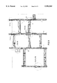
- FIG. 9 is a front view of the scaffold assembly according to the invention.
- the lifting scaffold assembly 10 shown in the drawings has several scaffolding poles 11 which stand on the ground 12 (see FIGS. 1A and 1B) or on a platform above the ground, each scaffolding pole being formed of pole sections mounted end-to-end. Between the scaffolding poles 11 mobile platforms 13 are provided, i.e., platforms which are connected to adjacent scaffolding poles to be independently vertically movable relative to a building face 15. The scaffolding poles 11 are attached to a building face 15 by means of several holding supports 14 (FIG. 1B).
- a scaffolding pole 11 of the lifting scaffold assembly 10 consists of two girder sections 16, 17 and a corner section 18, whereby the girder sections 16, 17 and the corner section 18 create a isosceles triangle.
- the girder sections 16, 17 and the corner section 18 are stabilized by cross- and oblique-running struts 19, 20, 21.
- the mobile section 22 is attached with the inner profile flange 26 on the inner side of the girder section 16, while free profile flange 27 is bent inward by 90°.
- a gear rack 28 is provided, on which a cogwheel 29 of a sliding block (carriage) 30 runs, the carriage providing a support wheel (3) which contacts the opposite side of the free flange 27 is (see FIG. 3A).
- the dotted line 32 in FIG. 4 designates a line of symmetry and in the top view a plane of symmetry between the left and right areas of the lifting pole 11 shown in FIG. 8.
- the construction pieces 33, 34, 35, 36, 30, 37 on the right side of the plane of symmetry 32 correspond to the construction pieces 26, 27, 28, 29, 30, 31 on the left side of the plane of symmetry 32.
- a mobile platform 38 with railings 39, 40 and 41, as well as with shiftable railing 42 is arranged on the right side of the plane of symmetry 32 in FIG. 4 .
- a bracket 44 is provided on which two cogwheels 45 to be driven are provided, which run in a gear rack 46 of the girder section 17.
- two opposing castors 47, 48 are provided on the bracket 44 and a castor 50 is also provided in an additional bracket 49, through which it is ensured that the cogwheel 45 remains constantly in secure contact with the gear rack 46.
- the drive of the cogwheel 45 derives from the shaft 51.
- a current collector 52 is provided, which is held on the conducting rail 25 such that the current collection can be shifted and slide on the conduction rail 25.
- a current collector 53 is provided on the sliding block 30, which is contacted tightly againist the conduction rail 24 or rather slides in the conduction rail 24.
- the mobile platform 54 has railings 55, 56 which correspond to the railings 39, 41.
- the railing 57 which corresponds to railing 42 is shiftable toward the facade on the left side of the plane of symmetry 32 and the folded railings 39 and 55 are released toward the facade so that the mobile platform lies quite close to the facade 15, so that accidents become impossible.
- variable length holding support 14 is arranged between a bearing 59 and a hook 60.
- a motor 61 which drives the drive shaft 51 over a gear 62 and over cogwheel 63, 64.
- a elevator 65 is arranged on a sliding block 30, which is swivelled on joints 66, 67 across from the sliding block 30.
- the elevator 65 is turned 90° around the joint 66 relative to the longitudinal orientation of the scaffold.
- the material and/or personnel elevator 65 is oriented in the direction of the scaffold.
- the elevator has turnable doors 68, 69 through which to attend to and access the individual platforms, provided that the platform itself is not moving.
- FIG. 6 differs from those shown in FIGS. 7A, 7B and 8 in that instead of the elevator 65, a crane 70 with a sectioned crane jib 71 is provided.
- the remaining arrangements are similar to the arrangements described above or are otherwise known.
- a clamp 72 is provided on the sliding block 30 of the scaffolding pole 11, both of whose jaws 73, 74 are opened and closed by a wheel 75.
- a section of scaffolding pole 76 is clamped, which is turned 180° relative to the already built scaffolding pole 11 and in this state can be lifted by means of the sliding block 30 and the pincers 72 and turned back 180° at the desired height, so that it is aligned with the already built scaffolding pole 11 and can be erected on this and connected thereto.
- FIGS. 3B and 3C the sliding block is represented by itself.
- a bar 77 is driven by the motor 61, which has two screws 78, 79 over which the four cogwheels 29 are driven by means of axles 80, 81.
- axles 80, 81 the support wheels are represented.
- a round disk 82 is provided which is attached to the pincers 72 of the sliding block 30.
- a bracket 83 is provided, on which the bracket 85 is mounted flexibly in a joint 84.
- a multiple-leveled cylinder 88 is provided in a joint 86 of the plate 82 and a joint 87 of the bracket 85 and with the help of which the joint 86 can be turned on the arc of a circle around the joint 84 until the disk 82 takes the position perpendicular to this.
- a driving chain 91 is provided between two chain wheels 89, 90, so that a forced synchronism is achieved.
Landscapes
- Engineering & Computer Science (AREA)
- Structural Engineering (AREA)
- Civil Engineering (AREA)
- Transportation (AREA)
- Mechanical Engineering (AREA)
- Automation & Control Theory (AREA)
- Architecture (AREA)
- Life Sciences & Earth Sciences (AREA)
- Geology (AREA)
- Movable Scaffolding (AREA)
- Types And Forms Of Lifts (AREA)
- Cyclones (AREA)
Priority Applications (1)
| Application Number | Priority Date | Filing Date | Title |
|---|---|---|---|
| US08/927,480 US5992565A (en) | 1994-03-03 | 1997-09-11 | Lifting scaffold assembly |
Applications Claiming Priority (4)
| Application Number | Priority Date | Filing Date | Title |
|---|---|---|---|
| DE4406987A DE4406987C1 (de) | 1994-03-03 | 1994-03-03 | Hubgerüst |
| DE4406987 | 1994-03-03 | ||
| US39794495A | 1995-03-03 | 1995-03-03 | |
| US08/927,480 US5992565A (en) | 1994-03-03 | 1997-09-11 | Lifting scaffold assembly |
Related Parent Applications (1)
| Application Number | Title | Priority Date | Filing Date |
|---|---|---|---|
| US39794495A Continuation | 1994-03-03 | 1995-03-03 |
Publications (1)
| Publication Number | Publication Date |
|---|---|
| US5992565A true US5992565A (en) | 1999-11-30 |
Family
ID=6511719
Family Applications (1)
| Application Number | Title | Priority Date | Filing Date |
|---|---|---|---|
| US08/927,480 Expired - Fee Related US5992565A (en) | 1994-03-03 | 1997-09-11 | Lifting scaffold assembly |
Country Status (8)
| Country | Link |
|---|---|
| US (1) | US5992565A (de) |
| EP (1) | EP0670399B1 (de) |
| JP (1) | JPH07259322A (de) |
| KR (1) | KR950031861A (de) |
| AT (1) | ATE156226T1 (de) |
| CA (1) | CA2143813A1 (de) |
| DE (2) | DE4406987C1 (de) |
| ES (1) | ES2107869T3 (de) |
Cited By (15)
| Publication number | Priority date | Publication date | Assignee | Title |
|---|---|---|---|---|
| KR20010099053A (ko) * | 2001-08-20 | 2001-11-09 | 백수곤 | 다기능 신속조립 비계틀 |
| WO2003097513A3 (en) * | 2002-05-20 | 2004-02-05 | Andre St-Germain | Tower for supporting an elevator thereon |
| US20080236944A1 (en) * | 2004-07-12 | 2008-10-02 | Bruno Patron | Platform Support Device For Lifting Loads Or Persons The Height Of A Structure |
| US20130081352A1 (en) * | 2011-09-27 | 2013-04-04 | Chicago Bridge & Iron Company | Freestanding elevator platform system |
| US20140034418A1 (en) * | 2011-04-14 | 2014-02-06 | Mantenimientos Electricos Campo De Aviacion, S.L. | Repair/cleaning scaffolding tower for wind turbines |
| CN103821341A (zh) * | 2014-03-10 | 2014-05-28 | 成都嘉泽正达科技有限公司 | 附着式自动升降多层施工平台 |
| US20180179770A1 (en) * | 2016-12-23 | 2018-06-28 | Tries Gmbh & Co. Kg | Climbing device having a climbing rail |
| US20200095784A1 (en) * | 2017-05-08 | 2020-03-26 | Kewazo Gmbh | Scaffold transport system, method for controlling a scaffold transport system and use of a scaffold transport system |
| CN112854701A (zh) * | 2021-01-15 | 2021-05-28 | 施明娣 | 一种可调节高度的稳定型工程建筑施工架 |
| CN112942785A (zh) * | 2019-12-11 | 2021-06-11 | 上海雅跃智能科技有限公司 | 带行轨的爬架 |
| US11053699B2 (en) * | 2017-10-27 | 2021-07-06 | Doka Gmbh | Climbing shoe, safety screen support system and safety screen system |
| US20210261273A1 (en) * | 2020-02-21 | 2021-08-26 | Daniel Johnston | Aircraft gantry system |
| US20240200344A1 (en) * | 2022-12-15 | 2024-06-20 | Gramercy Group Inc. | Scaffolding system |
| US12065265B2 (en) * | 2020-03-16 | 2024-08-20 | Daniel Johnston | Aircraft wing gantry system |
| US12234127B2 (en) * | 2017-06-26 | 2025-02-25 | Inventio Ag | Elevator system |
Families Citing this family (11)
| Publication number | Priority date | Publication date | Assignee | Title |
|---|---|---|---|---|
| DE4443629C3 (de) * | 1994-12-08 | 2001-10-25 | Geda Dechentreiter Gmbh & Co K | Überlastsicherung für einen Bauaufzug |
| SE516701C2 (sv) * | 1999-11-04 | 2002-02-12 | Alimak Ab | Hissystem |
| DE102006055253B4 (de) | 2006-04-05 | 2018-09-27 | Sew-Eurodrive Gmbh & Co Kg | Fördervorrichtung |
| DE102006029653B4 (de) | 2006-06-28 | 2009-02-12 | Doka Industrie Gmbh | Hubplattform und Verfahren zum Aufbauen einer Hubplattform |
| CN103375022B (zh) * | 2012-04-13 | 2016-09-21 | 保定市裕升建筑安装股份有限公司 | 多功能动轨式附着升降脚手架 |
| CN103375023A (zh) * | 2012-04-27 | 2013-10-30 | 广州市达蒙建筑技术有限公司 | 附着式升降脚手架 |
| DE102015004392A1 (de) * | 2015-04-10 | 2016-10-13 | Senvion Gmbh | Personenhebevorrichtung für Windenergieanlagentürme |
| DE102016223913A1 (de) * | 2016-12-01 | 2018-06-07 | Thyssenkrupp Ag | Aufzuganlage mit einer Stromschiene und einem Stromabnehmer |
| CN109704248B (zh) * | 2019-01-17 | 2023-12-29 | 大连理工大学 | 可折叠升降的飞机维修脚手架单元 |
| CN111021703A (zh) * | 2019-12-31 | 2020-04-17 | 陕西开友实业有限公司 | 同步升降脚手架 |
| CN115893281B (zh) * | 2022-12-23 | 2024-09-13 | 湖南中联重科应急装备有限公司 | 调平装置和高空作业平台 |
Citations (17)
| Publication number | Priority date | Publication date | Assignee | Title |
|---|---|---|---|---|
| US2390284A (en) * | 1942-04-15 | 1945-12-04 | Franks Mfg Corp | Derrick structure |
| US3548970A (en) * | 1968-08-05 | 1970-12-22 | Ralph W Hutchens Sr | Scaffolding and material handling system |
| DE2163507A1 (de) * | 1971-12-21 | 1973-07-05 | Harald Kreybu | Geruest, insbesondere fuer malerarbeiten |
| DE2347974A1 (de) * | 1972-09-25 | 1974-04-04 | Eaton Corp | Durch einen elektromotor angetriebener foerderwagen fuer zu lagernde gegenstaende |
| US3878916A (en) * | 1973-02-07 | 1975-04-22 | Jr Gerome R White | Rack and pinion drive counterbalanced hoist systems |
| US3937301A (en) * | 1973-03-20 | 1976-02-10 | Philippe Bertail | Trailer having a self-lifting platform |
| US4293054A (en) * | 1980-05-19 | 1981-10-06 | Piat Impalcature Automatiche S.P.A. | Scaffolding for supporting lifting working bridges and platforms |
| US4294332A (en) * | 1979-04-13 | 1981-10-13 | Ready Delbert L | Scaffold with gear drive |
| DE3114602A1 (de) * | 1981-04-10 | 1984-04-26 | VEB Kombinat für Baureparaturen und Rekonstruktion, DDR 7010 Leipzig | Einrichtung fuer arbeitsgerueste mit heb- und senkbarer arbeitsbuehne |
| DE3420737A1 (de) * | 1983-08-16 | 1985-03-07 | VEB Baumechanisierung Dresden, DDR 8029 Dresden | Zusatzeinrichtung fuer hoehenverstellbare arbeitsgerueste |
| DE3415074A1 (de) * | 1984-04-21 | 1985-10-24 | Lissmac Maschinenbau GmbH, 7971 Aitrach | Hubarbeitsbuehne |
| DE3526105A1 (de) * | 1984-08-10 | 1986-02-20 | VEB (B) Bauinvest Dresden, DDR 8060 Dresden | Geruest fuer reparaturarbeiten an fassaden und dachtraufen |
| US4655319A (en) * | 1985-01-18 | 1987-04-07 | Gilbert Loix | Folding ladder |
| EP0418173A1 (de) * | 1989-09-11 | 1991-03-20 | Charles Boudrot | Teleskopartiges Gerüst für Hocharbeitsbühne |
| US5067587A (en) * | 1990-12-28 | 1991-11-26 | William F. Mims, Jr. | Service platform for mobile scaffolding unit |
| FR2667582A1 (fr) * | 1990-10-04 | 1992-04-10 | Cgti | Dispositif pour le levage et l'installation d'un materiel au sommet d'un ouvrage de grande hauteur. |
| US5159993A (en) * | 1991-10-15 | 1992-11-03 | Gestion Des Brevets Fraco Limitee | Self-raising work platform assembly |
Family Cites Families (2)
| Publication number | Priority date | Publication date | Assignee | Title |
|---|---|---|---|---|
| US3085650A (en) * | 1961-01-26 | 1963-04-16 | Andrew W Merk | Orchard platform |
| AT237875B (de) * | 1962-06-01 | 1965-01-11 | Giuseppe Pieri | Zerlegbares Gerüst |
-
1994
- 1994-03-03 DE DE4406987A patent/DE4406987C1/de not_active Expired - Fee Related
-
1995
- 1995-02-21 AT AT95102391T patent/ATE156226T1/de not_active IP Right Cessation
- 1995-02-21 DE DE59500425T patent/DE59500425D1/de not_active Expired - Fee Related
- 1995-02-21 ES ES95102391T patent/ES2107869T3/es not_active Expired - Lifetime
- 1995-02-21 EP EP95102391A patent/EP0670399B1/de not_active Revoked
- 1995-02-27 KR KR1019950003902A patent/KR950031861A/ko not_active Withdrawn
- 1995-02-28 JP JP7040664A patent/JPH07259322A/ja active Pending
- 1995-03-02 CA CA002143813A patent/CA2143813A1/en not_active Abandoned
-
1997
- 1997-09-11 US US08/927,480 patent/US5992565A/en not_active Expired - Fee Related
Patent Citations (17)
| Publication number | Priority date | Publication date | Assignee | Title |
|---|---|---|---|---|
| US2390284A (en) * | 1942-04-15 | 1945-12-04 | Franks Mfg Corp | Derrick structure |
| US3548970A (en) * | 1968-08-05 | 1970-12-22 | Ralph W Hutchens Sr | Scaffolding and material handling system |
| DE2163507A1 (de) * | 1971-12-21 | 1973-07-05 | Harald Kreybu | Geruest, insbesondere fuer malerarbeiten |
| DE2347974A1 (de) * | 1972-09-25 | 1974-04-04 | Eaton Corp | Durch einen elektromotor angetriebener foerderwagen fuer zu lagernde gegenstaende |
| US3878916A (en) * | 1973-02-07 | 1975-04-22 | Jr Gerome R White | Rack and pinion drive counterbalanced hoist systems |
| US3937301A (en) * | 1973-03-20 | 1976-02-10 | Philippe Bertail | Trailer having a self-lifting platform |
| US4294332A (en) * | 1979-04-13 | 1981-10-13 | Ready Delbert L | Scaffold with gear drive |
| US4293054A (en) * | 1980-05-19 | 1981-10-06 | Piat Impalcature Automatiche S.P.A. | Scaffolding for supporting lifting working bridges and platforms |
| DE3114602A1 (de) * | 1981-04-10 | 1984-04-26 | VEB Kombinat für Baureparaturen und Rekonstruktion, DDR 7010 Leipzig | Einrichtung fuer arbeitsgerueste mit heb- und senkbarer arbeitsbuehne |
| DE3420737A1 (de) * | 1983-08-16 | 1985-03-07 | VEB Baumechanisierung Dresden, DDR 8029 Dresden | Zusatzeinrichtung fuer hoehenverstellbare arbeitsgerueste |
| DE3415074A1 (de) * | 1984-04-21 | 1985-10-24 | Lissmac Maschinenbau GmbH, 7971 Aitrach | Hubarbeitsbuehne |
| DE3526105A1 (de) * | 1984-08-10 | 1986-02-20 | VEB (B) Bauinvest Dresden, DDR 8060 Dresden | Geruest fuer reparaturarbeiten an fassaden und dachtraufen |
| US4655319A (en) * | 1985-01-18 | 1987-04-07 | Gilbert Loix | Folding ladder |
| EP0418173A1 (de) * | 1989-09-11 | 1991-03-20 | Charles Boudrot | Teleskopartiges Gerüst für Hocharbeitsbühne |
| FR2667582A1 (fr) * | 1990-10-04 | 1992-04-10 | Cgti | Dispositif pour le levage et l'installation d'un materiel au sommet d'un ouvrage de grande hauteur. |
| US5067587A (en) * | 1990-12-28 | 1991-11-26 | William F. Mims, Jr. | Service platform for mobile scaffolding unit |
| US5159993A (en) * | 1991-10-15 | 1992-11-03 | Gestion Des Brevets Fraco Limitee | Self-raising work platform assembly |
Cited By (25)
| Publication number | Priority date | Publication date | Assignee | Title |
|---|---|---|---|---|
| KR20010099053A (ko) * | 2001-08-20 | 2001-11-09 | 백수곤 | 다기능 신속조립 비계틀 |
| WO2003097513A3 (en) * | 2002-05-20 | 2004-02-05 | Andre St-Germain | Tower for supporting an elevator thereon |
| US20080236944A1 (en) * | 2004-07-12 | 2008-10-02 | Bruno Patron | Platform Support Device For Lifting Loads Or Persons The Height Of A Structure |
| US9133632B2 (en) * | 2004-07-12 | 2015-09-15 | Fixator | Platform support device for lifting loads or persons the height of a structure |
| US20140034418A1 (en) * | 2011-04-14 | 2014-02-06 | Mantenimientos Electricos Campo De Aviacion, S.L. | Repair/cleaning scaffolding tower for wind turbines |
| US20130081352A1 (en) * | 2011-09-27 | 2013-04-04 | Chicago Bridge & Iron Company | Freestanding elevator platform system |
| US9150397B2 (en) * | 2011-09-27 | 2015-10-06 | Chicago Bridge & Iron Company | Freestanding elevator platform system |
| US20160010345A1 (en) * | 2011-09-27 | 2016-01-14 | Chicago Bridge & Iron Company | Freestanding elevator platform system |
| US9528282B2 (en) * | 2011-09-27 | 2016-12-27 | Chicago Bridge & Iron Company | Freestanding elevator platform system |
| CN103821341A (zh) * | 2014-03-10 | 2014-05-28 | 成都嘉泽正达科技有限公司 | 附着式自动升降多层施工平台 |
| CN103821341B (zh) * | 2014-03-10 | 2015-11-18 | 成都嘉泽正达科技有限公司 | 附着式自动升降多层施工平台 |
| US10465398B2 (en) * | 2016-12-23 | 2019-11-05 | Peri Gmbh | Climbing device having a climbing rail |
| US20200095785A1 (en) * | 2016-12-23 | 2020-03-26 | Peri Gmbh | Climbing device having a climbing rail |
| US20180179770A1 (en) * | 2016-12-23 | 2018-06-28 | Tries Gmbh & Co. Kg | Climbing device having a climbing rail |
| US11987998B2 (en) * | 2016-12-23 | 2024-05-21 | Peri Se | Climbing device having a climbing rail |
| US20200095784A1 (en) * | 2017-05-08 | 2020-03-26 | Kewazo Gmbh | Scaffold transport system, method for controlling a scaffold transport system and use of a scaffold transport system |
| US11821223B2 (en) * | 2017-05-08 | 2023-11-21 | Kewazo Gmbh | Scaffold transport system, method for controlling a scaffold transport system and use of a scaffold transport system |
| US12234127B2 (en) * | 2017-06-26 | 2025-02-25 | Inventio Ag | Elevator system |
| US11053699B2 (en) * | 2017-10-27 | 2021-07-06 | Doka Gmbh | Climbing shoe, safety screen support system and safety screen system |
| CN112942785A (zh) * | 2019-12-11 | 2021-06-11 | 上海雅跃智能科技有限公司 | 带行轨的爬架 |
| US20210261273A1 (en) * | 2020-02-21 | 2021-08-26 | Daniel Johnston | Aircraft gantry system |
| US12337998B2 (en) * | 2020-02-21 | 2025-06-24 | Daniel Johnston | Aircraft gantry system |
| US12065265B2 (en) * | 2020-03-16 | 2024-08-20 | Daniel Johnston | Aircraft wing gantry system |
| CN112854701A (zh) * | 2021-01-15 | 2021-05-28 | 施明娣 | 一种可调节高度的稳定型工程建筑施工架 |
| US20240200344A1 (en) * | 2022-12-15 | 2024-06-20 | Gramercy Group Inc. | Scaffolding system |
Also Published As
| Publication number | Publication date |
|---|---|
| EP0670399A1 (de) | 1995-09-06 |
| JPH07259322A (ja) | 1995-10-09 |
| EP0670399B1 (de) | 1997-07-30 |
| ES2107869T3 (es) | 1997-12-01 |
| DE4406987C1 (de) | 1995-07-06 |
| ATE156226T1 (de) | 1997-08-15 |
| DE59500425D1 (de) | 1997-09-04 |
| CA2143813A1 (en) | 1995-09-04 |
| KR950031861A (ko) | 1995-12-20 |
Similar Documents
| Publication | Publication Date | Title |
|---|---|---|
| US5992565A (en) | Lifting scaffold assembly | |
| US5884725A (en) | Scaffolding assembly | |
| EP0702121B1 (de) | Höhenverstellbare Arbeitsvorrichtung | |
| HU214726B (hu) | Eljárás és berendezés hidraulikus szerkezettel működő felvonó vezetősínjeinek aknában történő szerelésére | |
| US4555890A (en) | Process for the installation of curtain walls and apparatus for the execution of the process | |
| US3610368A (en) | Vertically adjustable platform for scaffolding | |
| HU192346B (en) | Scaffold for repair works to be carried out on the front and fence roof range of buildings | |
| CN212535708U (zh) | 一种公路隧道预制拼装波纹钢衬砌结构拼装平台 | |
| US5058708A (en) | Scaffold and hoist structure | |
| US4976086A (en) | Method and device for building a greenhouse | |
| JPH03110208A (ja) | 橋梁用移動式足場装置およびその組立方法 | |
| CN216196428U (zh) | 一种新型马头门作业施工平台 | |
| CN214328569U (zh) | 一种桥梁作业平台 | |
| JP7278863B2 (ja) | 昇降式足場の設置方法 | |
| JP3841242B2 (ja) | エレベータパーキング用昇降作業台とこれを用いた工法 | |
| CN113833244A (zh) | 一种悬挑式移动操作平台 | |
| CN114412160B (zh) | 一种便于组装的施工用可移动装饰装修操作平台 | |
| SU1694819A1 (ru) | Передвижные подмости | |
| JP2539142Y2 (ja) | 仮設屋根の昇降装置 | |
| CN221371840U (zh) | 一种桥梁施工作业用的移动式吊篮 | |
| JP2934567B2 (ja) | 立体駐車場建設用作業ゴンドラ | |
| SU1636548A1 (ru) | Устройство дл обслуживани кровли теплицы | |
| JPH11292483A (ja) | 旋回式高所作業台 | |
| SU1025654A1 (ru) | Устройство к мостовому крану дл обслуживани верхних участков помещений | |
| JPH0545724B2 (de) |
Legal Events
| Date | Code | Title | Description |
|---|---|---|---|
| REMI | Maintenance fee reminder mailed | ||
| FPAY | Fee payment |
Year of fee payment: 4 |
|
| SULP | Surcharge for late payment | ||
| REMI | Maintenance fee reminder mailed | ||
| LAPS | Lapse for failure to pay maintenance fees | ||
| STCH | Information on status: patent discontinuation |
Free format text: PATENT EXPIRED DUE TO NONPAYMENT OF MAINTENANCE FEES UNDER 37 CFR 1.362 |
|
| FP | Lapsed due to failure to pay maintenance fee |
Effective date: 20071130 |