US6032509A - Press brake - Google Patents
Press brake Download PDFInfo
- Publication number
- US6032509A US6032509A US09/251,523 US25152399A US6032509A US 6032509 A US6032509 A US 6032509A US 25152399 A US25152399 A US 25152399A US 6032509 A US6032509 A US 6032509A
- Authority
- US
- United States
- Prior art keywords
- configuration
- movable
- ram
- bed
- movable wedge
- Prior art date
- Legal status (The legal status is an assumption and is not a legal conclusion. Google has not performed a legal analysis and makes no representation as to the accuracy of the status listed.)
- Expired - Lifetime
Links
Images


Classifications
-
- B—PERFORMING OPERATIONS; TRANSPORTING
- B21—MECHANICAL METAL-WORKING WITHOUT ESSENTIALLY REMOVING MATERIAL; PUNCHING METAL
- B21D—WORKING OR PROCESSING OF SHEET METAL OR METAL TUBES, RODS OR PROFILES WITHOUT ESSENTIALLY REMOVING MATERIAL; PUNCHING METAL
- B21D5/00—Bending sheet metal along straight lines, e.g. to form simple curves
- B21D5/02—Bending sheet metal along straight lines, e.g. to form simple curves on press brakes without making use of clamping means
- B21D5/0272—Deflection compensating means
Definitions
- the present invention relates to a press brake for bending a workpiece between an upper mold set on a ram and a lower mold set on a bed, and comprises an adjusting unit for adjusting the distance between the upper and lower molds on a workpiece being bent.
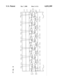
- FIG. 12 exemplifies structure of such a conventional press brake incorporating an adjusting unit 100.
- the reference numeral 101 shown in FIG. 12 designates an upper mold secured to a ram 104 via a holder 103, whereas the reference numeral 102 designates a lower mold held on a table 105.
- the adjusting unit 100 utilizes the principle of a wedge by way of combining a stationary wedge 111 with a movable wedge 112 to make up a wedging unit 110, which is installed between a bed 106 the table 105.
- the movable wedge 112 is interlinked with a reciprocating unit 120 driven by a motor 121.
- a motor 121 By causing the motor 121 to rotate itself in the clockwise and counterclockwise inverse directions, the movable wedge 112 reciprocates along the length of the molds.
- the movable wedge 112 and the stationary wedge 111 of the wedging unit 110 are stacked vertically in contact with each other.
- contacting surface 113 of the movable wedge 112 is in contact with the stationary wedge 111, and is formed of a plurality of inclined planes 113a ⁇ 113g having angles of inclination ⁇ 1 ⁇ 7
- the contacting surface 114 of the stationary wedge is also formed of inclined planes 114a ⁇ 114g having angles of inclination ⁇ 1 ⁇ 7 respectively.
- the inclined planes 114a ⁇ 114g of the stationary wedge 111 are respectively the same as the inclined planes 113a ⁇ 113g of the movable wedge 112, wherein each pair of planes contacting each other have identical angles of inclination ⁇ 1 ⁇ 7 are disposed in vertical engagement with their slopes being vertically inverse.
- the planes 113d and the planes 114d at the center positions are respectively set via the largest angle of inclination ⁇ 4, followed by the planes 113c, 114c, 113e, and 114e on both sides of the planes 113d and 114d which have the next largest angles of inclination ⁇ 3 and ⁇ 5.
- the angles of inclination decrease towards both ends.
- FIG. 13, and FIGS. 3, 7, 9 and 11 described later the angles of inclination of respective planes are magnified in order to facilitate explanation, however, actual angles of inclination do not permit visual confirmation.
- the upward planes 113a ⁇ 113g of the movable wedge 112 are respectively in contact with the corresponding downward planes 114a ⁇ 114g of the stationary wedge 111, although the center planes 113d and 114d of the movable wedge 112 and the stationary wedge 111 respectively have the largest angle of inclination " ⁇ 4". Therefore, assume that a pressure is applied to the stationary wedge 111 when it is displaced upward by the shift of the movable wedge 112, an amount of displacement at the center portion D is the largest, whereas the degree of upward displacement is gradually descended toward the end portions A and G to cause the stationary wedge 111 to curve the whole length.
- range a of pressure applied to a workpiece subject to a bending process via a press brake is not always be constant due to lengthwise differences per kind of the workpiece
- Length L of a workpiece W shown in FIG. 15 is shorter than distance "d" between the pair of driving units 107L and 107R disposed on both sides, whereas length L of another workpiece W shown in FIG. 16 substantially corresponds to the whole length D of the press brake unit.
- the above press brake is of such a structure that the ram 104 is subject to pressure at the positions of the driving units 107L ad 107R, whereas the bed 106 is loaded at the positions of a pair of frames 108L and 108R respectively aligned with the driving units 107L and 107R. Therefore, deflected conditions of the ram 104 and the bed 106 are different in accordance with the length L of workpieces W.
- ratios of the deflected amounts at positions X1 ⁇ X7 are not identical to each other.
- the curved deflection shown in FIG. 15 can properly be compensated, but the curved deflection shown in FIG. 16 cannot be compensated, so it is impossible to deal with workpieces having a variety of length, thus raising a problem.
- the invention is provided to fully solve the above problem.
- the object of the invention is to provide a novel press brake capable of setting a proper bending angle throughout the whole length of a workpiece independent of the length of the workpiece by way of composing a wedging unit to be capable of dealing with deflection of a variety of curved forms of the ram and the bed.
- a press brake which comprises a bed for supporting a lower mold on the upper surface thereof, a ram for supporting an upper mold in opposition to said lower mold, a driver for causing either the ram or the bed to move vertically for bending a workpiece between the upper and lower molds, and a distance adjusting device for adjusting the distance between the upper and lower molds.
- the distance adjusting device comprises a wedging unit which is disposed either between the ram and the upper mold or between the bed and the lower mold, and a pair of reciprocating units.
- the wedging unit comprises a pair of movable wedges and a stationary wedge disposed between the movable wedges and in contact with the movable wedges, wherein each of the contacting surfaces of the wedges is formed by a plurality of inclined planes having different angles of inclination in series.
- the reciprocating units are connected to the movable wedges respectively to move the movable wedges along the length of the molds.
- the stationary wedge and the upper movable wedge are integrally displaced in the vertical direction to an extent corresponding to the shifted amount of the lower wedge.
- the upper wedge is shifted, the upper wedge is displaced in the vertical direction in accordance with its own shift.
- the stationary wedge and the upper movable wedge are integrally displaced in the vertical direction to an extent corresponding to the shifted amounts of the both movable wedges.
- each of the contacting surfaces of the wedges is formed by a plurality of inclined planes having different angles of inclination in series, the displaced amounts at positions of the respective inclined planes agree with the sums of the displaced amounts at positions of the respective planes of the stationary wedge and the upper movable wedge. Therefore, by applying the sums of displaced amounts to the curved deflection of the ram and the bed, deflection of the ram and the bed can fully be corrected.
- the wedging unit can be operated to deal with a variety of curved deflections of the bed and the ram, and thus, workpieces having a variety of length can be bent at proper bending angles.
- An aspect of the distance adjusting device also comprises a pair of wedging units and a pair of reciprocating units corresponding to the wedging units, and the wedging units are disposed either between the ram and the upper mold or between the bed and the lower mold.
- the distance adjusting device may also comprise a pair of wedging units and a pair of reciprocating units corresponding to the wedging units, wherein one of the wedging units is disposed between the ram and the upper mold, and the other is disposed between the bed and the lower mold.
- each of the wedging units comprises a movable wedge and a stationary wedge which are vertically disposed being in contact with each other, wherein each of the contacting surfaces of the wedges is formed by a plurality of inclined planes having different angles of inclination in series.
- the reciprocating units are connected to the movable wedges of the wedging units respectively to move the movable wedges along the length of the molds.
- either the movable wedge or the stationary wedge in contact with the movable wedge is displaced in the vertical direction to an extent corresponding to the shifted amount of the movable wedge. Since each of the contacting surfaces of the wedges of the first and second wedging units is formed by a plurality of inclined planes having different angles of inclination in series, displaced amounts at the positions of respective inclined planes agree with the sums of the displaced amounts at the positions of respective planes of the stationary wedge or the movable wedge of the first wedging unit and the displaced amounts at the positions of respective planes of the stationary wedge or the movable wedge of the second wedging unit. By applying the sums of displaced amounts to the curved deflection of the ram and the bed, deflection of the ram and the bed can fully be corrected.
- the distance adjusting device in the above-referred aspects preferably comprises supporting means for supporting load(s) applied to the movable wedges during shifting thereof. Accordingly, in the course of shifting any movable wedge via operation of the corresponding reciprocating unit, the load applied to the movable wedge is supported by the supporting unit, so the movement of movable wedge and the displacement of the movable wedge and the stationary wedge in the vertical direction, can be done smoothly, to effectively prevent wear of the wedges.
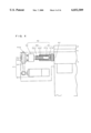
- FIG. 1 is a partial cross-sectional front view of a press brake according to an embodiment of the invention, showing the cross section of an adjusting unit for adjusting upper-lower molds distance;
- FIG. 2 is a cross-sectional view along line A--A of FIG. 1;
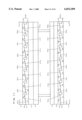
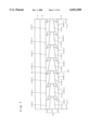
- FIG. 3 is an enlarged front view of a wedging unit
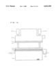
- FIG. 4 is a front view showing structure of a first reciprocating unit
- FIG. 5 is a plan view showing structure of the first reciprocating unit
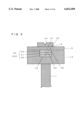
- FIG. 6 is a cross-sectional view showing structure of the supporting unit
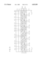
- FIG. 7 is an enlarged front view of a wedging unit according to another embodiment of the invention.
- FIG. 8 is a partial cross-sectional front view of a press brake according to another embodiment of the invention, showing a cross section of an adjusting unit;
- FIG. 9 is an enlarged front view of the wedging unit according to the embodiment shown in FIG. 8;
- FIG. 10 is a partial cross-sectional front view of a press brake according to another embodiment of the invention, showing a cross section of an adjusting unit;
- FIG. 11 is an enlarged front view of a wedging unit according to the embodiment shown in FIG. 10;
- FIG. 12 is a front view showing structure of a conventional press brake incorporating an adjusting unit
- FIG. 13 is an enlarged front view of a conventional wedging unit shown in FIG. 12;
- FIG. 14 is a view showing a deflected condition of a ram and a bed
- FIG. 15 is a view showing a deflected condition of a ram and a bed when bending a short workpiece.
- FIG. 16 is a view showing a deflected condition of a ram and a bed when bending a lengthy workpiece.
- FIG. 1 shows a press brake according to an embodiment of the invention.
- the reference numerals 1 and 2 shown in FIG. 1 respectively designate a bed and a ram vertically disposed in opposition to each other. End portions of the bed 1 are integrally supported by a pair of frames 3a and 3b.
- a pair of hydraulic cylinders 4a and 4b function as linear driving units and are disposed at upper ends of the frames 3a and 3b.
- the ram 2 is connected to the bottom ends of cylinder rods 5 of the hydraulic cylinders 4a and 4b of low parts at both ends of the ram 2.
- the driving units for moving the ram 2 up and down are not only limited to the hydraulic cylinders 4a and 4b but a Fair of ball-screws driven by discrete servomotors may also be used.
- the ram 2 is vertically operated.
- the scope of the invention is not solely limited to the ram's movement, but the invention is also applicable to such a version causing the bed 1 to move up and down as well.
- a table base 14 is integrally formed at the upper portion of the bed 1, and a wedging unit 30 of an adjusting unit 20 is held inside a supporting groove 15 formed on the upper surface of the table-base 14.
- Table 6 is held on the wedging unit i 30, and a lower mold 9 is secured onto the table 6.
- a upper mold 8 is secured to the bottom-end portion of the ram 2 via a holder 10.
- the respective cylinders 4a and 4b are operated to lower the ram 2. Then the workpiece is pressed into V-shaped groove 9a of the lower mold 9 by the upper mold 8 and bent.
- a control box 13 is set to a lateral surface of the press brake.
- the controller comprises a CPU for executing control and arithmetic operations and memories such as RAM and ROM.
- the controller is electrically connected an operation panel having a display and a keyboard.
- the wedging unit 30 includes an adjusting unit 20 for adjusting the distance between the upper-lower molds 8, 9, in conjunction with first and second reciprocating units 40A and 40B, or linear positions, at the ends, and a supporting unit 60 set to the table base 14.
- the wedging unit 30 of this embodiment is disposed between the table base 14 of the bed 1 and the table 6, and the unit 30 comprises a pair of movable wedges 32, 33 vertically opposed, and a stationary wedge 31 between the movable wedges 32, 33.
- the first movable wedge 32 disposed in the lower position is held by the supporting groove 15 of the table-base 14, and the upper surface of the wedge 32 and the bottom surface of the stationary wedge 31 are in firm contact with each other thereby providing first contacting surfaces 34 and 35.
- Upper surface of the stationary wedge 31 and the bottom surface of the second movable wedge 33 disposed in the upper position are in firm contact with each other thereby providing second contacting surfaces 36 and 37.
- the bottom surface of the first movable wedge 32 and the upper surface of the second movable wedge 33 are flattened.
- the table 6 is held on the upper surface of the second movable wedge 33.
- the first contacting surface 34 of the movable wedge 32 is formed by a plurality of upward inclined planes 34a ⁇ 34g having different angles of inclination ⁇ 1 ⁇ 7 in series.
- the first contacting surface 35 of the stationary wedge 31 comprises a plurality of downward inclined planes 35a ⁇ 35g opposed to said planes 34a ⁇ 34g and having angles of inclination ⁇ 1 ⁇ 7 identical to the opposite planes 34a ⁇ 34g respectively.
- the second contacting surface 36 of the stationary wedge 31 is formed by a plurality of upward inclined planes 36a ⁇ 36g having different angles of inclination ⁇ 1 ⁇ 7 in series.
- the second contacting surface 37 of the second movable wedge 33 comprises a plurality of downward inclined planes 37a ⁇ 37g opposed to the planes 36a ⁇ 36g and having angles of inclination ⁇ 1 ⁇ 7 to the opposite planes 36a ⁇ 36g respectively.
- the wedges 31, 32, and 33 exemplified have 7 inclined planes respectively, but the number of planes are not limited to 7. It should be understood that finer adjustment can be executed by way of increasing the number of the inclined planes. It is also practicable that each of the planes of the respective wedges 31, 32 and 33 is formed by combining plurality of inclined planes having different angles of inclination.
- angles of inclination ⁇ 1 ⁇ 7 of the planes 34a ⁇ 34g and 35a ⁇ 35g are respectively preset in order that the ratio of the angles ⁇ 1 ⁇ 7 coincides with the ratio of the sums of deflected amounts at said respective positions X1 ⁇ X7 in the curved deflection shown in FIG. 15.
- angles of inclination ⁇ 1 ⁇ 7 of the planes 36a ⁇ 36g and 37a ⁇ 37g are preset in order that ratio of the angles ⁇ 1 ⁇ 7 coincides with the ratio of the sums of deflected amounts at respective positions X1 ⁇ X7 in the curved deflection shown in FIG. 16.
- the stationary wedge 31 and the first and second movable wedges 32, 33 in this embodiment are integrated.
- coupling units 39 are preferably installed between adjoining blocks 32BL1 ⁇ 32BL7, and 33BL1 ⁇ 33BL7 to connect the blocks with each other and shift all the blocks simultaneously.
- first and second movable wedges 32 and 33 are respectively provided with two types of shifting units for shifting the wedges 32 and 33 toward the different directions respectively, the above coupling units 39 are not always required.
- the stationary wedge 31 and the movable wedges 32 and 33 are formed by way of coupling a plurality of blocks respectively, it is possible to freely combine sloped blocks each having different angles of inclination.
- FIGS. 4 and 5 respectively designate structure of the first reciprocating unit 40A.
- the reciprocating unit 40A causes the first movable wedge 32 to reciprocate along the length of the molds, where the lengthwise direction corresponds to the lateral direction in FIGS. 1 and 3, and the unit 40A is set to one end in the lateral direction of the bed 1.
- the other end of the bed 1 is provided with the second reciprocating unit 40B for causing the second movable wedge 33 to reciprocate along the length of the molds.
- the second reciprocating unit 40B has the same structure as that of the first reciprocating unit 40A, so the following description solely refers to the structure of the first reciprocating unit 40A and omits description of the second reciprocating unit 40B.
- the reciprocating unit 40A exemplified comprises a driver 41 and a transmission 42 which converts rotary movement of the driver 41 into linear movement to transmit the linear movement to the first movable wedge 32.
- the driver 41 comprises a motor 43 rotating in the clockwise and counterclockwise directions, a pulley 45 connected to the motor 43 via a belt 44, and a rotary shaft 46 connected to the pulley 45, by which the rotary shaft 46 integrally rotates with the rotation of the motor 43.
- the transmission 42 includes a internal thread 47 secured to the first movable wedge 32 and a external thread 49 connected to the rotary shaft 46 via a coupling 48.
- the internal thread 47 is provided by a cylindrical body 47a with a threaded hole 47b on the internal surface thereof.
- the external thread hole 47b on the internal surface thereof.
- the external thread 49 is provided by a shaft 49a provided with a screw thread 49b which is engaged to the thread 47b.
- the reference numeral 50 shown in FIG. 5 designates a cam moved by the internal thread 47 for turning on and off limit switches 51 and 52 in accordance with the reciprocation of the thread 47.
- the switches 51 and 52 are for restricting the movable range of the first movable wedge 32, and when the switches 51 and 52 are depressed by the cam 50, the motor 43 stops rotation.
- FIG. 6 designates structure of the supporting unit 60.
- the supporting unit 60 supports the load applied to the movable wedges 32 and 33 during their reciprocation.
- the supporting unit 60 pushes the table 6 onto the wedging unit 30 along the whole length of the table 6, after adjusting the distance between the molds by the reciprocation of the wedges 32 and 33, to cause the contacting surfaces 34 and 35 of the first movable wedge 32 and the stationary wedge 31 as well as the contacting surfaces 36 and 37 of the stationary wedge 31 and the second movable wedge 33, to respectively be in firm contact with each other.
- the supporting unit 60 exemplified comprises a predetermined number of pairs of cylinder units 61A and 61B respectively disposed before and behind along the length of the wedging unit 30 at predetermined intervals, in which the cylinder units 61A and 61B are respectively set inside of the table base 14.
- Each of the cylinder units 61A and 61B incorporates a piston 62 and a cylinder shaft 64 whose tip is secured to the table 6 with a bolt 63.
- the reference numeral 66 shown in FIG. 6 designates a washer integrated with the piston 62.
- spring pressure of a compressed spring 67 By causing spring pressure of a compressed spring 67 to act on the washer 66, the table 6 is pressed to the wedging unit 30.
- the wedging unit 30 is not necessarily disposed between the bed 1 and the table 6, it may be disposed between the ram 2 and the holder 10.
- the press brake according to the above embodiment comprises a single unit of the wedging unit 30 which is structured by combining a single unit of the stationary wedge 31 with a pair of movable wedges 32 and 33.
- the press brake may be also have a pair of wedging units 30A and 30B each having a single stationary wedge 31 and a single movable wedge 32.
- the wedging units 30A and 30B may be disposed vertically in contact with each other between the-bed 1 and the table 6 as shown in FIG. 8, or the wedging units 30A and 30B may be disposed between the bed 1 and the table 6 and between the ram 2 and the holder 10 respectively, as shown in FIG. 10.
- the first wedging unit 30A is disposed on the table base 14 of the bed 1
- the second wedging unit 30B is disposed on the first wedging unit 30A
- the table 6 is disposed on the second wedging unit 30B, serially contacting each other.
- the upper surface of the movable wedge 32 and the bottom surface of the stationary wedge 31 of the first wedging unit 30A are in firm contact with each other to respectively form the first contacting surfaces 34 and 35.
- the upper surface of the movable wedge 32 and the bottom surface of the stationary wedge 31 of the second wedging unit 30B are also in firm contact with each other to respectively form the second contacting surfaces 36 and 37.
- the movable wedges 32, 32 of the first and second wedging unit 30A and 30B are connected to the first and second reciprocating units 40A and 40B respectively for reciprocating the wedges 32, 32 along the length of the molds.
- the contacting surface 34 of the movable wedge 32 of the first wedging unit 30A is formed by a plurality of upward inclined planes 34a ⁇ 34g having different angles of inclination ⁇ 1 ⁇ 7 in series.
- the contacting surface 35 of the stationary wedge 31 comprises a plurality of downward inclined planes 35a ⁇ 35g opposed to said planes 34a ⁇ 34g and having angles of inclination ⁇ 1 ⁇ 7 identical to the opposite planes 34a ⁇ 34g respectively.
- the contacting surface 36 of the movable wedge 32 of the second wedge unit 30B comprises a plurality of upward inclined planes 36a ⁇ 36g having different angles of inclination ⁇ 1 ⁇ 7.
- the second contacting surface 37 of the stationary wedge 31 comprises of a plurality of downward inclined planes 37a ⁇ 37g opposed to said planes 36a ⁇ 36g and having angles of inclination ⁇ 1 ⁇ 7 identical to the opposite planes 36a ⁇ 36g respectively.
- angles of inclination ⁇ 1 ⁇ 7 of the planes 34a ⁇ 34g and 35a ⁇ 35g of the first wedging unit 30A are set so that the ratio of the angles ⁇ 1 ⁇ 7 coincides with that of the sums of deflected amounts at positions X1 ⁇ X7 in the curved deflection shown in FIG. 15.
- the angles of inclination ⁇ 1 ⁇ 7 of the planes 36a ⁇ 36g and 37a ⁇ 37g are set so that the ratio of the angles ⁇ 1 ⁇ 7 coincides with that of the sums of deflected amounts at positions X1 ⁇ X7 in the curved deflection shown in FIG. 16.
- both of the first and second wedging units 30A and 30B are disposed between the bed 1 and the table 6. However, it is also practicable to dispose them between the ram 2 and the holder 10.
- the stationary wedge 31 is displaced in the vertical direction via shifting movement of the movable wedge 32.
- the first wedging unit 30A is disposed between the bed 1 and the table 6, whereas the second wedging unit 30B is disposed between the ram 2 and the holder 10.
- the upper surface of the movable wedge 32 and the bottom surface of the stationary wedge 31 of the first wedging unit 30A are in firm contact with each other to form the first contacting surfaces 34 and 35.
- the bottom surface of the movable wedge 32 and the upper surface of the stationary wedge 31 of the second wedging unit 30B are in firm contact with each other to form the second contacting surfaces 36 and 37.
- the movable wedges 32, 32 of the first and second wedging unit 30A and 30B are connected to the first and second reciprocating unit 40A and 40B respectively to reciprocate the movable wedges 32 to along the length of the molds.
- the contacting surface 34 of the movable wedge 32 comprises a plurality of upward inclined planes 34a ⁇ 34g having different angles of inclination ⁇ 1 ⁇ 7.
- the contacting surface 35 of the stationary wedge 31 comprises a plurality of downward inclined planes 35a ⁇ 35g opposed to the planes 34a ⁇ 34g and having angles of inclination ⁇ 1 ⁇ 7 identical to the opposite planes 34a ⁇ 34g respectively.
- the contacting surface 36 of the movable wedge 32 comprises a plurality of downward inclined planes 36a ⁇ 36g having different angles of inclination ⁇ 1 ⁇ 7.
- the contacting surface 37 of the stationary wedge 31 comprises a plurality of continuing upward surfaces 37a ⁇ 37g opposed to the planes 36a ⁇ 36g and having angles of inclination ⁇ 1 ⁇ 7 identical to the opposite planes 36a ⁇ 36g respectively.
- angles of inclination ⁇ 1 ⁇ 7 of the planes 34a ⁇ 34g and 35a ⁇ 35g of the first wedging unit 30A are set so that the ratio of the angles ⁇ 1 ⁇ 7 coincides with the ratio of the sums of deflected amounts at positions X1 ⁇ X7 in the curved deflection shown in FIG. 15.
- angles of inclination ⁇ 1 ⁇ 7 of the planes 36a ⁇ 36g and 37a ⁇ 37g of the second wedging unit 30B are set so that the ratio of the angles ⁇ 1 ⁇ 7 coincides with the ratio of the sums of deflected amounts at positions X1 ⁇ X7 in the curved deflection shown in FIG. 16.
- each of the movable wedges 32 and 32 of the both wedging units 30A and 30B can be displaced in the vertical direction via shift of the movable wedge 32 itself.
- the displaced amounts at the positions X1 ⁇ X7 agree with the sums of deflected amounts of the bed 1 and the ram 2 at the respective positions. Accordingly, the distance between the upper mold 8 and the lower mold 9 in the course of the bending process is kept constant along the length of the molds 8 and 9, thus properly correcting the curved deflection of the bed 1A and the ram 2. In consequence, the workpiece can be bent by a proper bending angle throughout the whole length.
- the second reciprocating unit 40B is driven to shift the second movable wedge 33 with the respective pairs of cylinder units 61A and 61B of the supporting unit 60 being operated to support the load of the table 6 and the lower mold 9.
- the second movable wedge 33 is displaced upward by corresponding degrees to its own shifting amounts.
- the displaced amounts at positions X1 ⁇ X7 respectively coincide with the sums of deflected amounts of the bed 1 and the ram 2 at the respective positions. Accordingly, the distance between the upper mold 8 and the lower mold 9 in the course of the bending process can be kept constant along the length thereof, with the curved deflection of the bed 1 and the ram 2 being corrected. In consequence, the above workpiece can be bent by a proper bending angle throughout the whole length.
- the first and second reciprocating units 40A and 40B are respectively driven to cause the first and second movable wedges 32 and 33 to be shifted with the respective pairs of cylinders 61A and 61B of the supporting unit 60 being operated to support the load of the table 6 and the lower mold 9.
- the stationary wedge 31 is displaced upward by amounts corresponding to the shifted amounts of the first movable wedge 32, and the second movable wedge 33 is displaced upward by amounts corresponding to its own shifting amounts.
- the displaced amounts at positions X1 ⁇ X7 correspond to the sums of the displaced amounts of the stationary wedge 32 and the second movable wedge 33 at respective positions respectively.
Landscapes
- Engineering & Computer Science (AREA)
- Mechanical Engineering (AREA)
- Bending Of Plates, Rods, And Pipes (AREA)
Applications Claiming Priority (2)
| Application Number | Priority Date | Filing Date | Title |
|---|---|---|---|
| JP10-245129 | 1998-08-31 | ||
| JP24512998A JP4009018B2 (ja) | 1998-08-31 | 1998-08-31 | プレスブレーキ |
Publications (1)
| Publication Number | Publication Date |
|---|---|
| US6032509A true US6032509A (en) | 2000-03-07 |
Family
ID=17129068
Family Applications (1)
| Application Number | Title | Priority Date | Filing Date |
|---|---|---|---|
| US09/251,523 Expired - Lifetime US6032509A (en) | 1998-08-31 | 1999-02-17 | Press brake |
Country Status (4)
| Country | Link |
|---|---|
| US (1) | US6032509A (de) |
| EP (1) | EP0983807B1 (de) |
| JP (1) | JP4009018B2 (de) |
| DE (1) | DE69906896T2 (de) |
Cited By (5)
| Publication number | Priority date | Publication date | Assignee | Title |
|---|---|---|---|---|
| US6450004B1 (en) * | 2001-10-09 | 2002-09-17 | Douglas E. Edmondson | Press brake punch holder |
| US6725702B2 (en) | 2001-10-26 | 2004-04-27 | Ariel Financing Ltd. | Apparatus and method for overcoming angular deviations in a workpiece |
| CN102172681A (zh) * | 2010-12-31 | 2011-09-07 | 江苏亚威机床股份有限公司 | 一种折弯机下模抗挠度装置及其加工方法 |
| WO2016197550A1 (zh) * | 2015-06-12 | 2016-12-15 | 江苏中威重工机械有限公司 | 一种开口自动变距的下模装置 |
| CN118976838A (zh) * | 2024-09-29 | 2024-11-19 | 泰兴市诚驹汽车零部件制造有限公司 | 一种汽车零部件制造用的冲床模具的加固装置 |
Families Citing this family (6)
| Publication number | Priority date | Publication date | Assignee | Title |
|---|---|---|---|---|
| DE102007033199B3 (de) * | 2007-07-17 | 2008-07-03 | Eht Werkzeugmaschinen Gmbh | Verfahren und Biegemaschine zur Kompensation der Durchbiegung von Teilen dieser Biegemaschine |
| JP2013180340A (ja) * | 2012-03-05 | 2013-09-12 | Amada Co Ltd | プレスブレーキ |
| KR101533737B1 (ko) * | 2014-02-19 | 2015-07-03 | 주식회사 일우산업기계 | 절곡기의 베드 크라우닝 |
| KR102191863B1 (ko) * | 2019-01-23 | 2020-12-16 | 주식회사 일우산업기계 | 하부금형 클램핑수단을 구비한 절곡기 |
| CN110026456A (zh) * | 2019-05-24 | 2019-07-19 | 安徽联盟模具工业股份有限公司 | 一种整体波形斜块结构的精密折弯机机械补偿工作台 |
| JP7846904B2 (ja) * | 2023-07-21 | 2026-04-16 | 株式会社吉野機械製作所 | プレス機械 |
Citations (7)
| Publication number | Priority date | Publication date | Assignee | Title |
|---|---|---|---|---|
| DE2316953A1 (de) * | 1972-04-13 | 1973-10-25 | Haemmerle Ag Maschf | Biegewerkzeug |
| US3965721A (en) * | 1975-02-24 | 1976-06-29 | Hurco Manufacturing Company, Inc. | Adjustable die holder |
| US4354374A (en) * | 1979-12-24 | 1982-10-19 | Kabushiki Kaisha Komatsu Seisakusho | Bending press |
| JPS60244425A (ja) * | 1984-05-17 | 1985-12-04 | Amada Co Ltd | 曲げ機械のダイ装置 |
| JPH0255622A (ja) * | 1988-08-19 | 1990-02-26 | Yamazaki Mazak Corp | クラウニング装置付きプレスブレーキ及びそのワーク加工方法 |
| US5009098A (en) * | 1989-11-27 | 1991-04-23 | Machinefabriek Wila B.V. | Press and curve-forming means therefor |
| US5103665A (en) * | 1989-06-21 | 1992-04-14 | Machinefabriek Wila B.V. | Press and an automatic curve-forming device therefor |
Family Cites Families (2)
| Publication number | Priority date | Publication date | Assignee | Title |
|---|---|---|---|---|
| GB431457A (en) * | 1935-03-26 | 1935-07-08 | Weingarten Ag Maschf | Machines for shearing or bending the edges of metal sheets |
| JPH0829352B2 (ja) * | 1988-11-28 | 1996-03-27 | 株式会社小松製作所 | 鞍反り矯正板曲げ方法 |
-
1998
- 1998-08-31 JP JP24512998A patent/JP4009018B2/ja not_active Expired - Lifetime
-
1999
- 1999-02-17 US US09/251,523 patent/US6032509A/en not_active Expired - Lifetime
- 1999-05-11 DE DE69906896T patent/DE69906896T2/de not_active Expired - Lifetime
- 1999-05-11 EP EP99109439A patent/EP0983807B1/de not_active Expired - Lifetime
Patent Citations (7)
| Publication number | Priority date | Publication date | Assignee | Title |
|---|---|---|---|---|
| DE2316953A1 (de) * | 1972-04-13 | 1973-10-25 | Haemmerle Ag Maschf | Biegewerkzeug |
| US3965721A (en) * | 1975-02-24 | 1976-06-29 | Hurco Manufacturing Company, Inc. | Adjustable die holder |
| US4354374A (en) * | 1979-12-24 | 1982-10-19 | Kabushiki Kaisha Komatsu Seisakusho | Bending press |
| JPS60244425A (ja) * | 1984-05-17 | 1985-12-04 | Amada Co Ltd | 曲げ機械のダイ装置 |
| JPH0255622A (ja) * | 1988-08-19 | 1990-02-26 | Yamazaki Mazak Corp | クラウニング装置付きプレスブレーキ及びそのワーク加工方法 |
| US5103665A (en) * | 1989-06-21 | 1992-04-14 | Machinefabriek Wila B.V. | Press and an automatic curve-forming device therefor |
| US5009098A (en) * | 1989-11-27 | 1991-04-23 | Machinefabriek Wila B.V. | Press and curve-forming means therefor |
Cited By (6)
| Publication number | Priority date | Publication date | Assignee | Title |
|---|---|---|---|---|
| US6450004B1 (en) * | 2001-10-09 | 2002-09-17 | Douglas E. Edmondson | Press brake punch holder |
| US6725702B2 (en) | 2001-10-26 | 2004-04-27 | Ariel Financing Ltd. | Apparatus and method for overcoming angular deviations in a workpiece |
| CN102172681A (zh) * | 2010-12-31 | 2011-09-07 | 江苏亚威机床股份有限公司 | 一种折弯机下模抗挠度装置及其加工方法 |
| CN102172681B (zh) * | 2010-12-31 | 2015-08-19 | 江苏亚威机床股份有限公司 | 一种折弯机下模抗挠度装置及其加工方法 |
| WO2016197550A1 (zh) * | 2015-06-12 | 2016-12-15 | 江苏中威重工机械有限公司 | 一种开口自动变距的下模装置 |
| CN118976838A (zh) * | 2024-09-29 | 2024-11-19 | 泰兴市诚驹汽车零部件制造有限公司 | 一种汽车零部件制造用的冲床模具的加固装置 |
Also Published As
| Publication number | Publication date |
|---|---|
| JP4009018B2 (ja) | 2007-11-14 |
| JP2000071017A (ja) | 2000-03-07 |
| EP0983807A3 (de) | 2001-04-11 |
| EP0983807A2 (de) | 2000-03-08 |
| EP0983807B1 (de) | 2003-04-16 |
| DE69906896D1 (de) | 2003-05-22 |
| DE69906896T2 (de) | 2003-11-13 |
Similar Documents
| Publication | Publication Date | Title |
|---|---|---|
| US6032509A (en) | Press brake | |
| KR101614942B1 (ko) | 박판용접용 정밀 클램프 지그 | |
| JP5115158B2 (ja) | プレス機械 | |
| JPS62224426A (ja) | プレスブレーキにおけるクラウニング装置 | |
| KR101767345B1 (ko) | 다양한 반지름을 갖는 곡선 금속판 제작용 용접 지그 및 이를 이용한 용접 방법 | |
| JPH0353078B2 (de) | ||
| CN104037586B (zh) | 压接站 | |
| CN106003414B (zh) | 一种管桩合模螺栓的自动翻转系统 | |
| CN1091663C (zh) | 带有检测上下横梁挠曲并控制至少一个顶头系统的器具的压力弯曲机床 | |
| JP5197594B2 (ja) | パネル製造及び/又は加工機械 | |
| US5702733A (en) | Press working machine | |
| CN1091081A (zh) | 液压操纵的压弯机 | |
| KR101658986B1 (ko) | 파이프 성형장치 | |
| US4314471A (en) | Metal extrusion press-billet loader | |
| US7175415B2 (en) | Moulding system, in particular a calibration die | |
| JP2009006344A (ja) | ヘミング加工装置,ヘミング加工方法およびヘミング加工装置におけるスライド部の隙間調整方法 | |
| CN116276215B (zh) | 一种可自适应非平整工件的快捷式机械传动四爪同步夹具 | |
| JP7421043B2 (ja) | ワークの捻れ防止装置と、それを備える鉄筋の曲げ加工装置 | |
| KR930008594B1 (ko) | 피이드 로울장치 | |
| EP1509348B1 (de) | Automatische walzmaschine mit einer einführvorrichtung | |
| JP7846904B2 (ja) | プレス機械 | |
| CN117813169A (zh) | 弯曲加工机以及弯曲加工方法 | |
| JP2007290001A (ja) | ウォーム用平ダイス転造盤 | |
| JP7245330B2 (ja) | プレスブレーキおよび二次元湾曲加工品の製造方法 | |
| JP7565322B2 (ja) | 曲げ加工機、及び曲げ加工方法 |
Legal Events
| Date | Code | Title | Description |
|---|---|---|---|
| AS | Assignment |
Owner name: TOYOKOKI CO., LTD., JAPAN Free format text: ASSIGNMENT OF ASSIGNORS INTEREST;ASSIGNOR:NAGAKURA, SEIJU;REEL/FRAME:009782/0788 Effective date: 19990205 |
|
| STCF | Information on status: patent grant |
Free format text: PATENTED CASE |
|
| FPAY | Fee payment |
Year of fee payment: 4 |
|
| FPAY | Fee payment |
Year of fee payment: 8 |
|
| FPAY | Fee payment |
Year of fee payment: 12 |
|
| AS | Assignment |
Owner name: AMADA TOYO CO., LTD., JAPAN Free format text: CHANGE OF NAME;ASSIGNOR:TOYOKOKI CO., LTD.;REEL/FRAME:031316/0721 Effective date: 20100701 Owner name: AMADA CO. LTD., JAPAN Free format text: ASSIGNMENT OF ASSIGNORS INTEREST;ASSIGNOR:AMADA TOYO CO., LTD.;REEL/FRAME:031316/0221 Effective date: 20130831 |