US6032731A - Heat exchanger - Google Patents
Heat exchanger Download PDFInfo
- Publication number
- US6032731A US6032731A US09/265,987 US26598799A US6032731A US 6032731 A US6032731 A US 6032731A US 26598799 A US26598799 A US 26598799A US 6032731 A US6032731 A US 6032731A
- Authority
- US
- United States
- Prior art keywords
- heat exchanger
- tank
- elements
- exchanger according
- fluids
- Prior art date
- Legal status (The legal status is an assumption and is not a legal conclusion. Google has not performed a legal analysis and makes no representation as to the accuracy of the status listed.)
- Expired - Fee Related
Links
Images


Classifications
-
- F—MECHANICAL ENGINEERING; LIGHTING; HEATING; WEAPONS; BLASTING
- F28—HEAT EXCHANGE IN GENERAL
- F28D—HEAT-EXCHANGE APPARATUS, NOT PROVIDED FOR IN ANOTHER SUBCLASS, IN WHICH THE HEAT-EXCHANGE MEDIA DO NOT COME INTO DIRECT CONTACT
- F28D9/00—Heat-exchange apparatus having stationary plate-like or laminated conduit assemblies for both heat-exchange media, the media being in contact with different sides of a conduit wall
- F28D9/0031—Heat-exchange apparatus having stationary plate-like or laminated conduit assemblies for both heat-exchange media, the media being in contact with different sides of a conduit wall the conduits for one heat-exchange medium being formed by paired plates touching each other
- F28D9/0037—Heat-exchange apparatus having stationary plate-like or laminated conduit assemblies for both heat-exchange media, the media being in contact with different sides of a conduit wall the conduits for one heat-exchange medium being formed by paired plates touching each other the conduits for the other heat-exchange medium also being formed by paired plates touching each other
-
- F—MECHANICAL ENGINEERING; LIGHTING; HEATING; WEAPONS; BLASTING
- F28—HEAT EXCHANGE IN GENERAL
- F28F—DETAILS OF HEAT-EXCHANGE AND HEAT-TRANSFER APPARATUS, OF GENERAL APPLICATION
- F28F2250/00—Arrangements for modifying the flow of the heat exchange media, e.g. flow guiding means; Particular flow patterns
- F28F2250/10—Particular pattern of flow of the heat exchange media
- F28F2250/108—Particular pattern of flow of the heat exchange media with combined cross flow and parallel flow
-
- Y—GENERAL TAGGING OF NEW TECHNOLOGICAL DEVELOPMENTS; GENERAL TAGGING OF CROSS-SECTIONAL TECHNOLOGIES SPANNING OVER SEVERAL SECTIONS OF THE IPC; TECHNICAL SUBJECTS COVERED BY FORMER USPC CROSS-REFERENCE ART COLLECTIONS [XRACs] AND DIGESTS
- Y10—TECHNICAL SUBJECTS COVERED BY FORMER USPC
- Y10S—TECHNICAL SUBJECTS COVERED BY FORMER USPC CROSS-REFERENCE ART COLLECTIONS [XRACs] AND DIGESTS
- Y10S165/00—Heat exchange
- Y10S165/355—Heat exchange having separate flow passage for two distinct fluids
- Y10S165/356—Plural plates forming a stack providing flow passages therein
- Y10S165/373—Adjacent heat exchange plates having joined bent edge flanges for forming flow channels therebetween
- Y10S165/382—Overlapping flanges
Definitions
- the present invention relates to a heat exchanger for fluids such as liquids, steam, gases, etc. comprising a heat exchanger tank with two separated closed systems for the fluids, between which heat is to be exchanged.
- heat exchangers known in the art, e.g. so-called tube heat exchangers
- several heat exchanger bodies such as tubes are inserted into a tank in such a way, that they at their ends are sealingly connected to the tank gables, the outlet and inlet connections, respectively, to be attached to each tube.
- the main purpose of the present invention is to achieve a heat exchanger of the kind described in the beginning, with which the drawbacks of known exchangers are eliminated and a simple and uncomplicated design of the heat exchanger body is achieved.
- Another purpose is to present a heat exchanger which is easily redesigned for an extended capacity without complicating the connection for the inlet and the outlet.
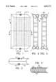
- FIG. 1 shows a front view of a heat exchanger designed according to the invention
- FIG. 2 shows a top view of a heat exchanger according to FIG. 1,
- FIG. 3 shows a cross section along the line III--III of the heat exchanger in FIG. 1,
- FIG. 4 shows a cross section along the line IV--IV of the heat exchanger in FIG. 1,
- FIG. 5 shows a cross section along the line V--V of the heat exchanger in FIG. 1,
- FIGS. 6a to 6c show a side view, a top view and a front view, respectively, of a half tube of which the heat exchanger is composed
- FIG. 7 shows a front view of several joint tube parts constituting the heat exchanger body
- FIG. 8 shows a top view of the heat exchanger body in FIG. 7,
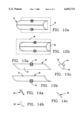
- FIGS. 9 and 10 show cross sections similar to FIG. 3 of alternative embodiments of the exchanger body
- FIGS. 11a, 11b and 11c show a front view, a side view and top view, respectively, of a heat exchanger with reinforcements
- FIGS. 12a and 12b show top views similar to FIG. 11c of alternative embodiments of the reinforcement
- FIGS. 13a to 13c show a side view, a top view and a front view, respectively, of the inlet and the outlet box for the heat exchanger in FIG. 1, and
- FIGS. 14a to 14c show a side view, a top view and a front view, respectively, of a covering plate to cover the channel openings in the heat exchanger body.
- the heat exchanger shown in FIG. 1 comprises a tank 10 composed of several curved elements, e.g. slotted tube parts 12, in the shown embodiment preferably half tubes, with their concave surfaces inserted into each other in accordance with FIG. 3 and fluidtightly assembled along their longitudinal edges 14. Between two adjoining elements 12 a channel 16 is formed running from one end of the tank 10 to the other, in the shown case between the upper and the lower end of the heat exchanger tank 10.
- Each element 12 is in accordance with FIGS. 6a to 6c at its ends symmetrically and conically bevelled in a V-shape so that the heat exchanger body or insert 18, as shown in FIG. 7, obtains bevelled or angled end surfaces.
- inlet and outlet boxes 20 are provided, in the shown example consisting of a semicircular mantle 22 being in accordance with FIGS. 13a to 13c open downwards, but closed at its end surfaces.
- a bound 24 adapted to connect supply means, such as ducts or similar (here not shown) for the supply of the fluids, between which the heat exchange has to occur.
- the inlet box 20 covers in accordance with FIGS. 4 and 5 one of the angled surfaces of the assembled tubular elements 12 at their upper and lower ends.
- covering washer 26 are arranged over half the width of each channel 16, in accordance with FIG. 8, in such a way, that the washers 26 alternate between both longsides of the exchanger body's 18 angled end surfaces.
- the design of the covering washers is shown in FIGS. 14a to 14c.
- the exchanger insert 18 terminates at one end of a tubular element, in the shown example a half tube, which eventually can be sealed by means of a plane end plate (here not shown).
- the insert can in accordance with FIG. 9 terminate with a complete tube 28, or, as shown in FIG. 10, with a T-shaped angled plate 30, extending along the exchanger body's 10 height.
- the angled plate's waist provides a reinforcement of the insert 18 for a higher pressure resistance, and for increasing the strength of the body and the insert 18 further in this respect plane reinforcement plates 32 are also arranged between the tube elements 12 as also shown in FIG. 10.
- reinforcement means e.g.
- the flanges 34 can then circumcize the complete heat exchanger, as shown in FIGS. 11a to 11c, and consist of one or several flanges 36 arranged around three sides of the exchanger 10, as shown in FIG. 12a, or one or several flanges 38 arranged around three sides of the exchanger and on one side supplemented by a cross bar 40, shown in FIG. 12b.
- a heat exchanger according to the invention having a simple and uncomplicated structure enabling a production of larger or smaller heat exchangers by means of simply adding the required number of elements 12.
- the heat exchanger 10 can be of any material whatsoever suitable for the application in question, such as metal, e.g. stainless, acid resistant steel or plastics and the fluidtight connections are achieved by means of welding, glueing or any other joining technique suitable for the application.
- the example in FIGS. 2 and 3 showsthat one medium is supplied at the exchanger upper side and is deducted at the bottom, whereas the other medium is supplied from beneath and deducted at the exchanger top so that the heat exchange is provided in contraflow.
- the inlet and outlet boxes 20 in combination with arranging the covering washers 26 other possibilities might of course be endeavoured, e.g. so that the media are supplied at one side and are deducted at the opposite side of the heat exchanger.
- the reinforcements 32 shown between the insert elements 12 can be designed in many ways and even other shapes of inserts might be arranged in the channels 16 for e.g. influencing the fluid flow.
Landscapes
- Engineering & Computer Science (AREA)
- Physics & Mathematics (AREA)
- Thermal Sciences (AREA)
- Mechanical Engineering (AREA)
- General Engineering & Computer Science (AREA)
- Heat-Exchange Devices With Radiators And Conduit Assemblies (AREA)
Applications Claiming Priority (2)
| Application Number | Priority Date | Filing Date | Title |
|---|---|---|---|
| SE9800934A SE510938C2 (sv) | 1998-03-20 | 1998-03-20 | Värmeväxlare uppbyggd av kupade plattor |
| SE9800934 | 1998-03-20 |
Publications (1)
| Publication Number | Publication Date |
|---|---|
| US6032731A true US6032731A (en) | 2000-03-07 |
Family
ID=20410626
Family Applications (1)
| Application Number | Title | Priority Date | Filing Date |
|---|---|---|---|
| US09/265,987 Expired - Fee Related US6032731A (en) | 1998-03-20 | 1999-03-11 | Heat exchanger |
Country Status (3)
| Country | Link |
|---|---|
| US (1) | US6032731A (de) |
| EP (1) | EP0943883A3 (de) |
| SE (1) | SE510938C2 (de) |
Cited By (2)
| Publication number | Priority date | Publication date | Assignee | Title |
|---|---|---|---|---|
| US6347662B1 (en) * | 1999-02-01 | 2002-02-19 | L'air Liquide, Societe Anonyme Pour L'etude Et L'exploitation Des Procedes Georges Claude | Heat exchanger, in particular plate heat exchanger for an air separation unit |
| US20030173067A1 (en) * | 2000-08-04 | 2003-09-18 | Leif Ramm-Schmidt | Apparatus for heat transfer between gas flows |
Citations (3)
| Publication number | Priority date | Publication date | Assignee | Title |
|---|---|---|---|---|
| US1197944A (en) * | 1914-09-17 | 1916-09-12 | Anders Johan Ericsson Munters | Apparatus for cooling or heating fluids. |
| SU1035399A1 (ru) * | 1982-02-02 | 1983-08-15 | Ленинградский Ордена Трудового Красного Знамени Технологический Институт Холодильной Промышленности | Пластинчатый теплообменник |
| US5121792A (en) * | 1987-12-10 | 1992-06-16 | Sita Maschinenbau- Und Forschungs Gmbh | Countercurrent heat-exchanger |
Family Cites Families (3)
| Publication number | Priority date | Publication date | Assignee | Title |
|---|---|---|---|---|
| FR1524141A (fr) * | 1967-01-31 | 1968-05-10 | Brissonneau & Lotz | Echangeurs plans pour le traitement de produits dont les dépôts adhèrent fortement aux parois |
| US4098330A (en) * | 1976-07-23 | 1978-07-04 | General Motors Corporation | Annular metal recuperator |
| DE3207881C1 (en) * | 1982-03-05 | 1983-10-06 | Salzgitter Ag | Heat exchanger profile |
-
1998
- 1998-03-20 SE SE9800934A patent/SE510938C2/sv not_active IP Right Cessation
-
1999
- 1999-03-11 US US09/265,987 patent/US6032731A/en not_active Expired - Fee Related
- 1999-03-17 EP EP99850039A patent/EP0943883A3/de not_active Withdrawn
Patent Citations (3)
| Publication number | Priority date | Publication date | Assignee | Title |
|---|---|---|---|---|
| US1197944A (en) * | 1914-09-17 | 1916-09-12 | Anders Johan Ericsson Munters | Apparatus for cooling or heating fluids. |
| SU1035399A1 (ru) * | 1982-02-02 | 1983-08-15 | Ленинградский Ордена Трудового Красного Знамени Технологический Институт Холодильной Промышленности | Пластинчатый теплообменник |
| US5121792A (en) * | 1987-12-10 | 1992-06-16 | Sita Maschinenbau- Und Forschungs Gmbh | Countercurrent heat-exchanger |
Cited By (3)
| Publication number | Priority date | Publication date | Assignee | Title |
|---|---|---|---|---|
| US6347662B1 (en) * | 1999-02-01 | 2002-02-19 | L'air Liquide, Societe Anonyme Pour L'etude Et L'exploitation Des Procedes Georges Claude | Heat exchanger, in particular plate heat exchanger for an air separation unit |
| US20030173067A1 (en) * | 2000-08-04 | 2003-09-18 | Leif Ramm-Schmidt | Apparatus for heat transfer between gas flows |
| US6758261B2 (en) * | 2000-08-04 | 2004-07-06 | Oy Casparado Ab | Apparatus for heat transfer between gas flows |
Also Published As
| Publication number | Publication date |
|---|---|
| SE9800934L (sv) | 1999-07-12 |
| SE510938C2 (sv) | 1999-07-12 |
| EP0943883A2 (de) | 1999-09-22 |
| SE9800934D0 (sv) | 1998-03-20 |
| EP0943883A3 (de) | 2000-03-08 |
Similar Documents
| Publication | Publication Date | Title |
|---|---|---|
| EP0772018B1 (de) | Wärmeübertrager zum Kühlen von Abgas | |
| US6516874B2 (en) | All welded plate heat exchanger | |
| US9212854B2 (en) | Plate and gasket for a plate heat exchanger | |
| US9714796B2 (en) | Plate heat exchanger and method for manufacturing of a plate heat exchanger | |
| PT2728292T (pt) | Placa de transferência de calor e permutador de calor de placas compreendendo essa placa de transferência de calor | |
| GB2166862A (en) | Vehicle radiator | |
| EP1348099A1 (de) | Wärmeübertragungsplatte; plattenpackung und plattenwärmetauscher | |
| US4596287A (en) | Flow distributor for a heat exchanger | |
| EP0715144B1 (de) | Plattenstapel für einen Wärmetauscher | |
| US4775006A (en) | Heat exchanger, particularly a coolant evaporator | |
| EP0086503B1 (de) | Vorrichtung zur Diffusion von Stoffen zwischen zwei Fluiden durch semipermeable Membranen | |
| JPH05507348A (ja) | プレート形熱交換器 | |
| ES2744461T3 (es) | Intercambiador de calor de placas | |
| US6032731A (en) | Heat exchanger | |
| JPS6365164A (ja) | 燃料予熱器 | |
| WO2018162199A1 (en) | Plate package, plate and heat exchanger device | |
| US4625794A (en) | Plastic heat exchanger construction | |
| US7222664B2 (en) | Heat exchanger plate and this exchanger | |
| KR970007278A (ko) | 열 교환기용 냉매 유통관 | |
| RU2213610C1 (ru) | Распределитель жидкости для колонн | |
| DE69803265T2 (de) | Wärmetauscher mit verbesserter Wärmeübertragung | |
| US4337217A (en) | Contacting arrangement for mass transfer operations and set of plates for use in said arrangement | |
| US4190038A (en) | Solar heater | |
| EP0199320B1 (de) | Wärmetauscher | |
| US4422936A (en) | Device for the diffusion of substances between two fluids via semipermeable membranes |
Legal Events
| Date | Code | Title | Description |
|---|---|---|---|
| REMI | Maintenance fee reminder mailed | ||
| LAPS | Lapse for failure to pay maintenance fees | ||
| FP | Expired due to failure to pay maintenance fee |
Effective date: 20040307 |
|
| STCH | Information on status: patent discontinuation |
Free format text: PATENT EXPIRED DUE TO NONPAYMENT OF MAINTENANCE FEES UNDER 37 CFR 1.362 |