US6032763A - Equipment for immobilizing an elevator car - Google Patents
Equipment for immobilizing an elevator car Download PDFInfo
- Publication number
- US6032763A US6032763A US09/055,571 US5557198A US6032763A US 6032763 A US6032763 A US 6032763A US 5557198 A US5557198 A US 5557198A US 6032763 A US6032763 A US 6032763A
- Authority
- US
- United States
- Prior art keywords
- track
- carriage
- elevator car
- groove
- immobilizing
- Prior art date
- Legal status (The legal status is an assumption and is not a legal conclusion. Google has not performed a legal analysis and makes no representation as to the accuracy of the status listed.)
- Expired - Fee Related
Links
Images

Classifications
-
- B—PERFORMING OPERATIONS; TRANSPORTING
- B66—HOISTING; LIFTING; HAULING
- B66B—ELEVATORS; ESCALATORS OR MOVING WALKWAYS
- B66B7/00—Other common features of elevators
- B66B7/02—Guideways; Guides
- B66B7/022—Guideways; Guides with a special shape
-
- B—PERFORMING OPERATIONS; TRANSPORTING
- B66—HOISTING; LIFTING; HAULING
- B66B—ELEVATORS; ESCALATORS OR MOVING WALKWAYS
- B66B5/00—Applications of checking, fault-correcting, or safety devices in elevators
- B66B5/02—Applications of checking, fault-correcting, or safety devices in elevators responsive to abnormal operating conditions
- B66B5/16—Braking or catch devices operating between cars, cages, or skips and fixed guide elements or surfaces in hoistway or well
- B66B5/18—Braking or catch devices operating between cars, cages, or skips and fixed guide elements or surfaces in hoistway or well and applying frictional retarding forces
-
- B—PERFORMING OPERATIONS; TRANSPORTING
- B66—HOISTING; LIFTING; HAULING
- B66B—ELEVATORS; ESCALATORS OR MOVING WALKWAYS
- B66B7/00—Other common features of elevators
- B66B7/02—Guideways; Guides
- B66B7/04—Riding means, e.g. Shoes, Rollers, between car and guiding means, e.g. rails, ropes
- B66B7/048—Riding means, e.g. Shoes, Rollers, between car and guiding means, e.g. rails, ropes including passive attenuation system for shocks, vibrations
Definitions
- the invention relates to equipment for immobilizing an elevator car movable along a track wherein the car is releasably connected with the track.
- a rod for the actuation of the safety devices which are arranged one at each side of the elevator car, is pivoted outwardly, wherein a roller of the safety device is moved on an inclined track until the roller wedges between the track and the leg of the guide rail.
- a disadvantage of the above described known equipment is that the place at which the elevator car can be fixed is predetermined by the location of the abutment.
- a further disadvantage is that the roller wedged between the track and guide rail can be freed again only with difficulty after the fixing of the elevator car.
- the equipment according to the present invention has the object of avoiding the disadvantages of the known equipment and of creating an apparatus by means of which the elevator car is easily immobilized and releasable at a desired position in the elevator shaft with little effort.
- the advantages achieved by the equipment according to the present invention are essentially to be seen in that during assembly and/or maintenance operations a secure, releasable connection of the elevator car with the track guide elements is producible, wherein the fixing equipment engages in grooves of the guide elements and on release is constrainably guided back into its rest setting. It is further of advantage of the equipment according to the present invention that workable clamping devices of the elevator drive can be released only after immobilization of the elevator car. Also of advantage is that the elevator car does not have to be raised for release from the fixed position.
- FIG. 1 is a top plan view of an elevator carriage that is movable along a track for guiding an elevator car;
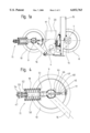
- FIG. 1a is a side elevation view of the carriage shown in the FIG. 1;
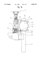
- FIG. 1b is an enlarged top plan view of the immobilization equipment arranged at a lower yoke of the carriage as shown in the FIG. 1;
- FIG. 2 is an enlarged view of a portion of the FIG. 1b showing details of the immobilization equipment arranged at the lower yoke;
- FIG. 2a is an enlarged view of a portion of the FIG. 2 designated by "A1" with details of the connection between the immobilization equipment and the track for the elevator car;
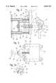
- FIG. 3 is an enlarged view of the immobilization equipment shown in the FIG. 2;
- FIG. 4 is an enlarged view of a support wheel that is mounted at a support axle of the elevator drive shown in the FIG. 1a;
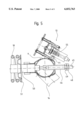
- FIG. 5 is an enlarged view of the immobilization equipment arranged at the support axle shown in the FIG. 1a.
- FIGS. 1 through 5 there is shown a carriage 1 that carries an elevator car (not shown) and which essentially consists of a drive unit 2, a spaced, generally parallel support unit 3 and a pair of spaced lower yokes 4 each connecting adjacent ends of the drive and support units.
- the carriage 1 is moveable along a pair of spaced apart tracks 5, for example vertically extending tracks, one such track adjacent each side of the carriage outside of the lower yokes 4.
- the drive unit 2 consists of a motor 6, a drive axle 7 driven by the motor and a respective drive wheel 8 mounted at each end of the drive axle and which rolls along one of the tracks 5.
- the support unit 3 consists of a respective support wheel 10 mounted at each end of a support axle 9 and a pair of clamping devices 11 attached to the support axle and each adjacent one of the support wheels.
- the clamping devices 11 bias the drive wheels 8 and the support wheels 10 against opposite sides of the tracks 5 to produce a friction drive.
- the working range of each of the clamping devices 11 can be read off of an associated indicator 12.
- equipment for fixing of the elevator car along a path of travel identified as immobilizing equipment 13 in the following.
- the immobilizing equipment 13 which includes a clamping element, the elevator car can be releasably connected with the track 5 at a desired position of the travel path during assembly of the elevator and/or during maintenance operations.
- FIG. 1a is a side view of the carriage 1.
- the drive axle 7 of the drive unit 2 is carried at each end by a respective support 14 rotatably connected with the lower yoke 4.
- a respective vertical yoke 15 is connected with the lower yoke 4 at each side.
- An upper yoke which is not illustrated, is arranged at the upper end of each of the vertical yokes 15.
- the lower yoke 4, the drive axle 7, the vertical yoke 15 and the upper yoke form the support frame for the elevator car (not shown).
- the support axle 9 of the support unit 3 is carried at each end by a respective rocker 16 rotatably connected with the lower yoke 4 and is biased in the direction of the track 5 by the respective clamping device 11 engaging at each end at the support axle.
- a first pull rod 17 of the clamping device 11 is connected at one end with the lower yoke 4, whilst at the other end the first pull rod is connected with a second pull rod 47 (FIG. 4).
- a compression spring 18 (FIG. 4) presses the drive wheel 8 and the support wheel 10 against a respective running surface 19 (FIG. 1b) of the track 5 and thereby produces the friction force necessary for travel of the elevator car.
- An opening 20, into which the immobilizing equipment 13 is insertable, is provided at the lower yoke 4.
- the track 5 which is constructed as a hollow body, has a longitudinally extending brake leg 21 formed thereon for engaging a brake, which brake is arranged at the carriage 1 and is not illustrated.
- a respective longitudinally extending anchoring groove 22 is formed which serves for the connection with the immobilizing equipment 13.
- Guides 23 for guidance of a counterweight, which is not illustrated, are provided in the cavity or hollow interior of the track 5.
- the FIGS. 2, 2a and 3 show details of the immobilizing equipment 13 and its engagement with the track 5.
- the immobilizing equipment 13 consists of a body 24 with an axially extending projection 25, an axially extending handle 26 arranged at the projection 25, and a pair of groove blocks 27 extending from the body opposite to the projection.
- the immobilizing equipment 13 is inserted into the opening 20 of the lower yoke 4 and is made fast to a strap 28 of a carrier plate 29 by means of a first screw 30.
- the carrier plate 29 has the same opening 20 as the lower yoke 4 formed therein and is made fast to the lower yoke by means of a second screw 31.
- a first bore 32 extending into the body 24 receives the first screw 30 for the fastening of the immobilizing equipment 13 to the lower yoke 4.
- a second bore 33 extending into the body 24 functions for the fastening of the immobilizing equipment 13 to the support axle 9.
- a respective one of the groove blocks 27 is seated at the end of each of a pair of third screws 34, which screws longitudinally penetrate the body 24.
- a second compression spring 35 is axially arranged in the body 24 and presses the third screw 34 out of the body 24 on release of the connection with the track 5 and lifts the groove block 27 out of the anchoring groove 22.
- the handle 26 is fastened to the end face of the projection 25 by means of a fourth screw 36 and has sleeves 37 projecting laterally of the projection 25.
- a respective pin 38 is guided in each sleeve 37 and projects partly out of the sleeve.
- a third compression spring 39 is co-axially arranged at the projecting part of each of the pins 38.
- the body 24, the handle 26, the groove blocks 27, and the third screws 34 form a clamping element that is manually connectable with the track 5 as described below.
- the strap 28 has a slot-shaped opening formed therein, into which the screw shank of the first screw 30 is pushed during mounting of the immobilizing equipment 13 and the first screw 30 is tightened without further measures. Then the third screw 34 is advanced against the spring force of the second compression spring 35 and turned. The groove block 27 guided in an undercut 40 of the body 24 is rotated with the third screw 34 until a first nose 41 of the groove block is aligned with a wall 42 of the anchoring groove 22, wherein the first nose 41 engages behind a second nose 43 of the anchoring groove 22. On tightening of the third screw 34, the second nose 43 is clamped on between the first nose 41 and the body 24, whereby the carriage 1 is releasably connected with the track 5.
- the cables or the counterweight can now be carried out free of risk and without the carriage 1 together with the elevator car being able to automatically travel freely in the upward direction or the downward direction.
- the third screw 34 is released and the groove block 27 is turned back into its starting position.
- the second compression spring 35 has the effect that the groove block 27 is automatically drawn out of the anchoring groove 22. Loose groove blocks 27 in the anchoring groove 22 are not possible.
- the first screw 30 is released.
- the third compression spring 39 has the effect that the immobilizing equipment 13 is pushed away from the lower yoke 4.
- FIG. 4 shows details of the clamping device 11 and the support axle 9.
- a first threaded sleeve 44 Arranged at the support axle 9 is a first threaded sleeve 44, by means of which, as shown in the FIG. 5, the immobilizing equipment 13 is made fast to the support axle.
- a threaded pin 45 Arranged at the end of the first pull rod 17 is a threaded pin 45, which pin can be screwed into a threaded sleeve 46 of the second pull rod 47.
- a first nut 48 is turned against a second nut 49 of the threaded sleeve 46 for securing the threaded pin 45.
- the second pull rod 47 is guided in a hollow axle 50 over which the first compression spring 18 is co-axially arranged.
- the first compression spring 18 ends at a fixed pressure plate 51.
- the second end of the first compression spring 18 is held by a pressure plate 52 displaceable at the hollow axle 50.
- a bushing 53 is arranged at the end of the second pull rod 47 and secured by means of a split pin 54.
- the bushing 53 is connected with the displaceable pressure plate 52.
- the immobilizing equipment 13 is arranged at the support axle 9.
- a fifth screw 55 is inserted into the second bore 33 of the body 24 and is screwed into the first threaded sleeve 44 of the support axle 9.
- the immobilizing equipment 13 placed on the support axle 9 prevents access to the first nut 48 and the second nut 49. Before the clamping device 11 can be operated, the immobilizing equipment 13 must be removed.
Landscapes
- Engineering & Computer Science (AREA)
- Mechanical Engineering (AREA)
- Lift-Guide Devices, And Elevator Ropes And Cables (AREA)
- Cage And Drive Apparatuses For Elevators (AREA)
- Forklifts And Lifting Vehicles (AREA)
- Maintenance And Inspection Apparatuses For Elevators (AREA)
Applications Claiming Priority (2)
| Application Number | Priority Date | Filing Date | Title |
|---|---|---|---|
| CH84897 | 1997-04-11 | ||
| CH0848/97 | 1997-04-11 |
Publications (1)
| Publication Number | Publication Date |
|---|---|
| US6032763A true US6032763A (en) | 2000-03-07 |
Family
ID=4196624
Family Applications (1)
| Application Number | Title | Priority Date | Filing Date |
|---|---|---|---|
| US09/055,571 Expired - Fee Related US6032763A (en) | 1997-04-11 | 1998-04-06 | Equipment for immobilizing an elevator car |
Country Status (6)
| Country | Link |
|---|---|
| US (1) | US6032763A (de) |
| EP (1) | EP0870718B1 (de) |
| JP (1) | JPH10279221A (de) |
| AT (1) | ATE243650T1 (de) |
| CA (1) | CA2234543A1 (de) |
| DE (1) | DE59808783D1 (de) |
Cited By (5)
| Publication number | Priority date | Publication date | Assignee | Title |
|---|---|---|---|---|
| WO2007046742A1 (en) * | 2005-10-21 | 2007-04-26 | Alimak Ab | Safety arrangement for a lift car in a lift |
| US20100038184A1 (en) * | 2007-01-05 | 2010-02-18 | Continental Teves Ag & Co. Ohg | Lift System Having A Lift Car With A Brake Device Which Is Arranged In The Region Of The Lift Car For Holding And Braking The Lift Car, And A Method For Holding And Braking A Lift Car Of This Type |
| US20100089705A1 (en) * | 2007-01-05 | 2010-04-15 | Steffen Grundmann | Apparatus and method for holding and braking an elevator car |
| CN104495261A (zh) * | 2014-12-10 | 2015-04-08 | 嘉善天慧光电科技有限公司 | 饲料送料平台 |
| CN112088138A (zh) * | 2018-05-14 | 2020-12-15 | 三菱电机株式会社 | 电梯的安全装置和电梯的安全系统 |
Families Citing this family (7)
| Publication number | Priority date | Publication date | Assignee | Title |
|---|---|---|---|---|
| EP1860051B1 (de) * | 2006-05-24 | 2010-10-06 | Inventio AG | Aufzug mit Reibungsantrieb |
| SG137753A1 (en) | 2006-05-24 | 2007-12-28 | Inventio Ag | Elevator with frictional drive |
| CN104925616B (zh) * | 2015-05-20 | 2019-04-12 | 杨伦 | 一种避免发生剪切事故电梯 |
| CN110526076A (zh) * | 2019-09-26 | 2019-12-03 | 西继迅达(许昌)电梯有限公司 | 一种复式楼电梯导靴 |
| BR112022011691A2 (pt) | 2019-12-18 | 2022-09-06 | Inventio Ag | Método para erguimento de uma instalação de elevador |
| DE112021007262T5 (de) * | 2021-03-08 | 2023-12-28 | Mitsubishi Electric Corporation | Lasttransporteinrichtung |
| CN113203009B (zh) * | 2021-05-10 | 2022-11-18 | 马伟元 | 一种医疗检测设备辅助移动装置 |
Citations (9)
| Publication number | Priority date | Publication date | Assignee | Title |
|---|---|---|---|---|
| US483145A (en) * | 1892-09-27 | ailes | ||
| US605820A (en) * | 1898-06-14 | Island | ||
| GB191101621A (en) * | 1911-01-21 | 1911-08-17 | Charles Harry Sivel | Improved Safety Apparatus for Mining Cages, Lifts, and the like. |
| US1124804A (en) * | 1913-12-22 | 1915-01-12 | John Remjas | Elevator safety device. |
| US1129536A (en) * | 1914-05-06 | 1915-02-23 | Andrew Barash | Safety device for elevators. |
| GB1023227A (en) * | 1962-05-15 | 1966-03-23 | Mufulira Copper Mines Ltd | A device for locking a conveyance in a shaft |
| US4113119A (en) * | 1977-02-10 | 1978-09-12 | Si Handling Systems, Inc. | Apparatus for loading articles onto vertically spaced horizontally disposed shelves |
| EP0081212A1 (de) * | 1981-12-03 | 1983-06-15 | SOCIETE D'EXPLOITATION DES ETABLISSEMENTS TABBONE FRERES S.A.R.L. dite: | Sicherheitsvorrichtung für Personen- oder Lastenaufzug |
| US5497855A (en) * | 1994-09-15 | 1996-03-12 | Moore; Chester G. | Exterior fire fighting and evacuation system for high rise buildings |
-
1998
- 1998-04-01 AT AT98105942T patent/ATE243650T1/de not_active IP Right Cessation
- 1998-04-01 EP EP98105942A patent/EP0870718B1/de not_active Expired - Lifetime
- 1998-04-01 DE DE59808783T patent/DE59808783D1/de not_active Expired - Fee Related
- 1998-04-06 US US09/055,571 patent/US6032763A/en not_active Expired - Fee Related
- 1998-04-08 CA CA002234543A patent/CA2234543A1/en not_active Abandoned
- 1998-04-10 JP JP10099048A patent/JPH10279221A/ja not_active Ceased
Patent Citations (9)
| Publication number | Priority date | Publication date | Assignee | Title |
|---|---|---|---|---|
| US483145A (en) * | 1892-09-27 | ailes | ||
| US605820A (en) * | 1898-06-14 | Island | ||
| GB191101621A (en) * | 1911-01-21 | 1911-08-17 | Charles Harry Sivel | Improved Safety Apparatus for Mining Cages, Lifts, and the like. |
| US1124804A (en) * | 1913-12-22 | 1915-01-12 | John Remjas | Elevator safety device. |
| US1129536A (en) * | 1914-05-06 | 1915-02-23 | Andrew Barash | Safety device for elevators. |
| GB1023227A (en) * | 1962-05-15 | 1966-03-23 | Mufulira Copper Mines Ltd | A device for locking a conveyance in a shaft |
| US4113119A (en) * | 1977-02-10 | 1978-09-12 | Si Handling Systems, Inc. | Apparatus for loading articles onto vertically spaced horizontally disposed shelves |
| EP0081212A1 (de) * | 1981-12-03 | 1983-06-15 | SOCIETE D'EXPLOITATION DES ETABLISSEMENTS TABBONE FRERES S.A.R.L. dite: | Sicherheitsvorrichtung für Personen- oder Lastenaufzug |
| US5497855A (en) * | 1994-09-15 | 1996-03-12 | Moore; Chester G. | Exterior fire fighting and evacuation system for high rise buildings |
Cited By (11)
| Publication number | Priority date | Publication date | Assignee | Title |
|---|---|---|---|---|
| WO2007046742A1 (en) * | 2005-10-21 | 2007-04-26 | Alimak Ab | Safety arrangement for a lift car in a lift |
| US20090159372A1 (en) * | 2005-10-21 | 2009-06-25 | Alimak Ab | Safety Arrangement for a Lift Car in a Lift |
| CN101321679B (zh) * | 2005-10-21 | 2010-10-27 | 阿力马克公司 | 用于电梯中的电梯厢的安全装置 |
| US8875845B2 (en) | 2005-10-21 | 2014-11-04 | Alimak Ab | Safety arrangement for a lift car in a lift |
| US20100038184A1 (en) * | 2007-01-05 | 2010-02-18 | Continental Teves Ag & Co. Ohg | Lift System Having A Lift Car With A Brake Device Which Is Arranged In The Region Of The Lift Car For Holding And Braking The Lift Car, And A Method For Holding And Braking A Lift Car Of This Type |
| US20100089705A1 (en) * | 2007-01-05 | 2010-04-15 | Steffen Grundmann | Apparatus and method for holding and braking an elevator car |
| US8302739B2 (en) * | 2007-01-05 | 2012-11-06 | Continental Teves Ag & Co. Ohg | Brake device for a lift car |
| US8517150B2 (en) * | 2007-01-05 | 2013-08-27 | Inventio Ag | Apparatus and method for holding and braking an elevator car |
| CN104495261A (zh) * | 2014-12-10 | 2015-04-08 | 嘉善天慧光电科技有限公司 | 饲料送料平台 |
| CN112088138A (zh) * | 2018-05-14 | 2020-12-15 | 三菱电机株式会社 | 电梯的安全装置和电梯的安全系统 |
| CN112088138B (zh) * | 2018-05-14 | 2022-02-25 | 三菱电机株式会社 | 电梯的安全装置和电梯的安全系统 |
Also Published As
| Publication number | Publication date |
|---|---|
| DE59808783D1 (de) | 2003-07-31 |
| EP0870718A1 (de) | 1998-10-14 |
| JPH10279221A (ja) | 1998-10-20 |
| CA2234543A1 (en) | 1998-10-11 |
| ATE243650T1 (de) | 2003-07-15 |
| EP0870718B1 (de) | 2003-06-25 |
Similar Documents
| Publication | Publication Date | Title |
|---|---|---|
| FI98295C (fi) | Tarraaja | |
| MXPA01012570A (es) | Dispositivo paracaidas y procedimiento para desbloquear un dispositivo paracaidas. | |
| DE59309330D1 (de) | Bremssicherheitseinrichtung für eine Aufzugskabine | |
| US5715710A (en) | Portable anti-theft device for motor vehicle | |
| CA2408024A1 (en) | Braking device for a lift | |
| JPH10279221A (ja) | 昇降機ケージの固定用機器 | |
| US4333549A (en) | Car blocking apparatus | |
| KR100628002B1 (ko) | 견인활차 엘리베이터용 홀딩브레이크 | |
| KR19980042185A (ko) | 미끄럼이동안전장치 | |
| DE50104300D1 (de) | Bremsfangvorrichtung, insbesondere für Aufzugskabinen | |
| HK63197A (en) | Elevator apparatus | |
| JP2594868B2 (ja) | ブラシロールのロールチョック前後方向自動拘束装置 | |
| KR960008456Y1 (ko) | 엘리베이터 카용 마그네틱 브레이크장치 | |
| US5467969A (en) | Rope jack device for a shuttle | |
| JPH08133626A (ja) | エレベータのガイドシュー取替治具 | |
| JP2593511B2 (ja) | トラックブレーキ取付装置 | |
| CN219057572U (zh) | 一种便于钢板安全运输加工轨道车 | |
| JP2000302357A (ja) | セフティブロック一体型ローラガイド | |
| JPH0717331B2 (ja) | エレベーターの非常停止機構の試験装置 | |
| JPH11268648A (ja) | 鉄道車両用キャリパブレーキ装置の制輪子の引き抜き装置 | |
| KR940002544Y1 (ko) | 에스컬레이터의 핸드레일 구동장치 | |
| EP0687645B1 (de) | Einbaueinrichtung eines Hydraulikzylinders für Aufzug | |
| CN119796268A (zh) | 一种自锁式轨道止轮器 | |
| GB1578512A (en) | Buffer stop assembly with braking buffer device | |
| JP2001310732A (ja) | ワイヤロープ持上げ具、及び該持上げ具を使用したスケータに対するワイヤロープのクランプ方法 |
Legal Events
| Date | Code | Title | Description |
|---|---|---|---|
| AS | Assignment |
Owner name: INVENTIO AG, SWITZERLAND Free format text: ASSIGNMENT OF ASSIGNORS INTEREST;ASSIGNORS:RICHTER, UTZ;LIEBETRAU, CHRISTOPH;MORLOK, ALBRECHT;REEL/FRAME:009083/0730;SIGNING DATES FROM 19980318 TO 19980324 |
|
| FEPP | Fee payment procedure |
Free format text: PAYOR NUMBER ASSIGNED (ORIGINAL EVENT CODE: ASPN); ENTITY STATUS OF PATENT OWNER: LARGE ENTITY |
|
| FPAY | Fee payment |
Year of fee payment: 4 |
|
| FPAY | Fee payment |
Year of fee payment: 8 |
|
| REMI | Maintenance fee reminder mailed | ||
| LAPS | Lapse for failure to pay maintenance fees | ||
| STCH | Information on status: patent discontinuation |
Free format text: PATENT EXPIRED DUE TO NONPAYMENT OF MAINTENANCE FEES UNDER 37 CFR 1.362 |
|
| FP | Lapsed due to failure to pay maintenance fee |
Effective date: 20120307 |