US6032929A - Arrangement in connection with a yoke in a hoisting system for a derrick - Google Patents
Arrangement in connection with a yoke in a hoisting system for a derrick Download PDFInfo
- Publication number
- US6032929A US6032929A US09/091,553 US9155398A US6032929A US 6032929 A US6032929 A US 6032929A US 9155398 A US9155398 A US 9155398A US 6032929 A US6032929 A US 6032929A
- Authority
- US
- United States
- Prior art keywords
- hydraulic piston
- cylinder arrangements
- yoke
- piston
- sleeve
- Prior art date
- Legal status (The legal status is an assumption and is not a legal conclusion. Google has not performed a legal analysis and makes no representation as to the accuracy of the status listed.)
- Expired - Lifetime
Links
- 230000000712 assembly Effects 0.000 description 1
- 238000000429 assembly Methods 0.000 description 1
- 230000001627 detrimental effect Effects 0.000 description 1
Images
Classifications
-
- E—FIXED CONSTRUCTIONS
- E21—EARTH OR ROCK DRILLING; MINING
- E21B—EARTH OR ROCK DRILLING; OBTAINING OIL, GAS, WATER, SOLUBLE OR MELTABLE MATERIALS OR A SLURRY OF MINERALS FROM WELLS
- E21B15/00—Supports for the drilling machine, e.g. derricks or masts
-
- E—FIXED CONSTRUCTIONS
- E21—EARTH OR ROCK DRILLING; MINING
- E21B—EARTH OR ROCK DRILLING; OBTAINING OIL, GAS, WATER, SOLUBLE OR MELTABLE MATERIALS OR A SLURRY OF MINERALS FROM WELLS
- E21B19/00—Handling rods, casings, tubes or the like outside the borehole, e.g. in the derrick; Apparatus for feeding the rods or cables
- E21B19/02—Rod or cable suspensions
Definitions
- the present invention relates to an apparatus in connection with a derrick, comprising two or more hydraulic piston/cylinder arrangements for raising and lowering a yoke which travels on guide rails in the derrick itself.
- a derrick structure developed by the present inventor in 1987, that has shown great promise is the RamRigTM concept.
- Two hydraulic piston/cylinder arrangements are used in the derrick for raising and lowering the drill string.
- the cylinders operate between the drill floor and a yoke which travels on guide rails in the derrick itself.
- the advantages of this concept are numerous, some of the most important being that it is possible to place the drill floor at a higher level than the platform floor, that a derrick having significantly lower air resistance can be constructed, and that the most expensive components of the derrick attain higher safety and a longer lifetime.
- the object of the present invention is to solve important, practical problems in the realization of the RamRigTM concept. This object is achieved by means of the features apparent from the characterizing clause of the subsequently disclosed claim 1.
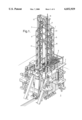
- FIG. 1 shows a RamRigTM derrick in every essential detail
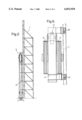
- FIG. 2 shows the derrick schematically, viewed from the side
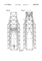
- FIG. 3 shows the derrick schematically, viewed from the front, with the top drive in its lowest position
- FIG. 4 shows the derrick schematically, viewed from the front, with the top drive in its highest position
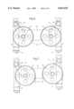
- FIG. 5 shows a yoke according to the invention, viewed from the front
- FIG. 6 shows the yoke of FIG. 6, viewed from the side
- FIG. 7 illustrates the self-adjusting function of the yoke.
- FIG. 1 shows a derrick 1 positioned on a drill floor 2.
- the drill floor is positioned at a higher level than the platform floor 3, so that the pipe handling equipment 4 can be placed, in the main, between the platform floor 3 and the drill floor 2.
- the derrick 1 is substantially gantry-shaped, with gantry legs 5, 6.
- Guide rails 7 for a yoke 8 and a top-drive 9 run along each gantry leg 5, 6.
- Hydraulic piston/cylinder arrangements 10, 11 are positioned so that they extend along each gantry leg 5, 6 and operate between the drill floor 2 and the yoke 8, for moving the yoke 8 vertically along the guide rails 7.
- the yoke 8 is provided with a plurality of sheaves 12, preferably four, for running wire lines 13.
- the wire lines 13 run from the drill floor 2 along each gantry leg 5, 6, over the sheaves 12 and down to the top drive 9.
- FIGS. 2, 3 and 4 the function of the lift system is seen most clearly.
- the piston/cylinder arrangement 10, 11 is shown in a completely retracted condition.
- the top drive 9 is then in its lowest position, quite close to the drill floor.
- the yoke 8 is at the upper end of the piston/cylinder arrangement.
- the yoke 8 When the pistons in the piston/cylinder arrangement are extended, the yoke 8 is lifted along the guide rails 7 up to the top of the derrick 1. The top drive is then lifted, as a result of the exchange created by the wire lines 13 being run over the sheaves 12, from its position adjacent to the drill floor 2 to a position directly below the yoke 8. The height to which the top drive 9 is lifted is thus the double of that to which the yoke 8 is lifted.
- the piston/cylinder arrangement 10 will never provide a lifting force and length of stroke completely identical to that of the piston/cylinder arrangement 11. Therefore, there is a great risk that misalignment of the yoke 8 will occur and that the yoke will become stuck in the guide rails 7. In order to avoid this, it is obviously possible to choose piston/cylinder arrangements of such powerful dimensions that they will overcome such misalignments. The result, however, is that the structure becomes very expensive and heavy. According to the invention, the yoke 8 has therefore been given a special design which will eliminate misalignment and the hazard of becoming stuck.
- FIGS. 5 and 6 The structure of the yoke 8 is best shown in FIGS. 5 and 6.
- Each of the piston rods 14 and 15 of the piston/cylinder arrangements 10, 11 is run through its own sleeve 16, 17 in the yoke 8.
- the top of the piston rods 14, 15 is attached to the top of the sleeves 16, 17 so that the attachment points of the piston rods 14, 15 are located above the sheaves 12.
- Arms 20, 21, carrying the sheaves 12 are attached at point 18, respectively point 19, adjacent to the top of the sleeves 16, 17.
- Each arm 20, 21 carries preferably two sheaves 12 at its end 22, respectively 23, opposite to the attachment points 18, 19.
- a beam 24, rigidly connected to the arms 20, 21, extends between the ends 22, 23 of the arms 20, 21, and provides a constant distance between the sheaves 12.
- FIG. 5 also shows the arrangement of the sheaves 12 in pairs.
- the piston/cylinder arrangement 10 When, for example, the piston/cylinder arrangement 10, as seen from FIG. 7, attains a somewhat higher lift position than the opposite piston/cylinder arrangement 11, the beam 24 with the sheaves 12 will be drawn toward the piston/cylinder arrangement 10. Hence, the horizontal distance between the attachment point 19 of the arm 21 in the sleeve 17, and the sheave 12 will decrease, so that the vertical force operating in point 19 will increase. The opposite will occur with respect to the piston/cylinder arrangement 11, where the horizontal distance between the point 18 and the pertaining sheave 12 will increase, so that the vertical force operating in point 18 will decrease. The piston/cylinder arrangement 10 will thus carry a greater portion of the total load than the piston/cylinder arrangement 11 does. The piston/cylinder arrangement 10 will therefore encounter greater resistance than the piston/cylinder arrangement 11 does, and the latter will thus catch up with the piston/cylinder arrangement 10, so that the misalignment will be cancelled before it reaches a value which may have a detrimental effect on the structure.
Landscapes
- Engineering & Computer Science (AREA)
- Geology (AREA)
- Life Sciences & Earth Sciences (AREA)
- Mining & Mineral Resources (AREA)
- Physics & Mathematics (AREA)
- Environmental & Geological Engineering (AREA)
- Fluid Mechanics (AREA)
- Mechanical Engineering (AREA)
- General Life Sciences & Earth Sciences (AREA)
- Geochemistry & Mineralogy (AREA)
- Earth Drilling (AREA)
- Jib Cranes (AREA)
- Manipulator (AREA)
Applications Claiming Priority (3)
| Application Number | Priority Date | Filing Date | Title |
|---|---|---|---|
| NO955270 | 1995-12-22 | ||
| NO955270A NO301384B1 (no) | 1995-12-22 | 1995-12-22 | Anordning ved åk i et heisesystem for et boretårn |
| PCT/NO1996/000290 WO1997023705A1 (fr) | 1995-12-22 | 1996-12-17 | Montage concernant un joug dans un systeme de hissage pour derrick |
Publications (1)
| Publication Number | Publication Date |
|---|---|
| US6032929A true US6032929A (en) | 2000-03-07 |
Family
ID=19898875
Family Applications (1)
| Application Number | Title | Priority Date | Filing Date |
|---|---|---|---|
| US09/091,553 Expired - Lifetime US6032929A (en) | 1995-12-22 | 1996-12-17 | Arrangement in connection with a yoke in a hoisting system for a derrick |
Country Status (10)
| Country | Link |
|---|---|
| US (1) | US6032929A (fr) |
| EP (1) | EP0868592B1 (fr) |
| JP (1) | JP2000502764A (fr) |
| KR (1) | KR19990076667A (fr) |
| AT (1) | ATE271646T1 (fr) |
| AU (1) | AU1213297A (fr) |
| CA (1) | CA2240659A1 (fr) |
| DE (1) | DE69632964D1 (fr) |
| NO (1) | NO301384B1 (fr) |
| WO (1) | WO1997023705A1 (fr) |
Cited By (12)
| Publication number | Priority date | Publication date | Assignee | Title |
|---|---|---|---|---|
| US20040098970A1 (en) * | 2002-11-25 | 2004-05-27 | Foster Michael R. | Apparatus and method for reduced cold start emissions |
| WO2008121071A1 (fr) * | 2007-04-02 | 2008-10-09 | Gva Consultants Ab | Dispositif de forage |
| US20080302096A1 (en) * | 2005-07-28 | 2008-12-11 | St Denis Perry L | Drive Assembly for a Reciprocating Pump Utilizing a Linear Actuator |
| US20130291668A1 (en) * | 2012-05-02 | 2013-11-07 | Robert Nickalos Heffner | Reciprocating Pump Drive Assembly |
| US20140060931A1 (en) * | 2012-08-31 | 2014-03-06 | Ensign Drilling Partnership | Systems and Methods for Automatic Drilling of Wellbores |
| US10174570B2 (en) * | 2013-11-07 | 2019-01-08 | Nabors Drilling Technologies Usa, Inc. | System and method for mud circulation |
| US10294735B2 (en) | 2014-04-08 | 2019-05-21 | Mhwirth As | Self-aligning apparatus |
| US10494881B2 (en) | 2015-05-04 | 2019-12-03 | Mhwirth As | Hoisting system |
| US10633936B2 (en) | 2015-10-08 | 2020-04-28 | Mhwirth As | Hoisting system |
| US10731426B2 (en) | 2017-06-15 | 2020-08-04 | Mhwirth As | Drilling system and method |
| US10745974B2 (en) | 2016-05-06 | 2020-08-18 | Mhwirth As | Hoisting system |
| US12031530B2 (en) | 2019-03-25 | 2024-07-09 | Mhwirth Gmbh | Pump and associated system and methods |
Families Citing this family (4)
| Publication number | Priority date | Publication date | Assignee | Title |
|---|---|---|---|---|
| US9458680B2 (en) | 2013-01-11 | 2016-10-04 | Maersk Drilling A/S | Drilling rig |
| GB2581164A (en) | 2019-02-06 | 2020-08-12 | Mhwirth Gmbh | Fluid pump, pump assembly and method of pumping fluid |
| GB2585681B (en) | 2019-07-11 | 2022-04-06 | Mhwirth As | Drilling rig systems |
| NO348003B1 (en) | 2022-11-28 | 2024-06-17 | Mhwirth As | Drilling system and method of operating a drilling system |
Citations (6)
| Publication number | Priority date | Publication date | Assignee | Title |
|---|---|---|---|---|
| US3494491A (en) * | 1966-10-29 | 1970-02-10 | Mitsubishi Heavy Ind Ltd | Materials handling vehicle |
| US4027854A (en) * | 1975-10-15 | 1977-06-07 | Mounton Jr William J | Self-equalizing linkage for well derricks |
| US4170340A (en) * | 1977-05-25 | 1979-10-09 | Mouton William J Jr | Hydraulic well derrick with cable lifts |
| US4341373A (en) * | 1977-05-25 | 1982-07-27 | Mouton Jr William J | Hydraulic well derrick with cable lifts |
| US4890671A (en) * | 1989-01-09 | 1990-01-02 | Baxter Bill V | Polished rod liner puller assembly |
| US5205379A (en) * | 1991-09-27 | 1993-04-27 | Pflow Industries Inc. | Vertical conveyor |
-
1995
- 1995-12-22 NO NO955270A patent/NO301384B1/no not_active IP Right Cessation
-
1996
- 1996-12-17 KR KR1019980704779A patent/KR19990076667A/ko not_active Ceased
- 1996-12-17 CA CA002240659A patent/CA2240659A1/fr not_active Abandoned
- 1996-12-17 WO PCT/NO1996/000290 patent/WO1997023705A1/fr not_active Ceased
- 1996-12-17 JP JP9523531A patent/JP2000502764A/ja active Pending
- 1996-12-17 DE DE69632964T patent/DE69632964D1/de not_active Expired - Lifetime
- 1996-12-17 US US09/091,553 patent/US6032929A/en not_active Expired - Lifetime
- 1996-12-17 AU AU12132/97A patent/AU1213297A/en not_active Abandoned
- 1996-12-17 AT AT96943393T patent/ATE271646T1/de not_active IP Right Cessation
- 1996-12-17 EP EP96943393A patent/EP0868592B1/fr not_active Expired - Lifetime
Patent Citations (6)
| Publication number | Priority date | Publication date | Assignee | Title |
|---|---|---|---|---|
| US3494491A (en) * | 1966-10-29 | 1970-02-10 | Mitsubishi Heavy Ind Ltd | Materials handling vehicle |
| US4027854A (en) * | 1975-10-15 | 1977-06-07 | Mounton Jr William J | Self-equalizing linkage for well derricks |
| US4170340A (en) * | 1977-05-25 | 1979-10-09 | Mouton William J Jr | Hydraulic well derrick with cable lifts |
| US4341373A (en) * | 1977-05-25 | 1982-07-27 | Mouton Jr William J | Hydraulic well derrick with cable lifts |
| US4890671A (en) * | 1989-01-09 | 1990-01-02 | Baxter Bill V | Polished rod liner puller assembly |
| US5205379A (en) * | 1991-09-27 | 1993-04-27 | Pflow Industries Inc. | Vertical conveyor |
Cited By (20)
| Publication number | Priority date | Publication date | Assignee | Title |
|---|---|---|---|---|
| US6931839B2 (en) | 2002-11-25 | 2005-08-23 | Delphi Technologies, Inc. | Apparatus and method for reduced cold start emissions |
| US20040098970A1 (en) * | 2002-11-25 | 2004-05-27 | Foster Michael R. | Apparatus and method for reduced cold start emissions |
| US20080302096A1 (en) * | 2005-07-28 | 2008-12-11 | St Denis Perry L | Drive Assembly for a Reciprocating Pump Utilizing a Linear Actuator |
| US8082734B2 (en) | 2005-07-28 | 2011-12-27 | 1238585 Alberta Ltd. | Drive assembly for a reciprocating pump utilizing a linear actuator |
| WO2008121071A1 (fr) * | 2007-04-02 | 2008-10-09 | Gva Consultants Ab | Dispositif de forage |
| US20090057011A1 (en) * | 2007-04-02 | 2009-03-05 | Inge Petersson | Drilling device |
| US7628225B2 (en) | 2007-04-02 | 2009-12-08 | Gva Consultants Ab | Drilling device |
| US8776627B2 (en) * | 2012-05-02 | 2014-07-15 | Amik Oilfield Equipment And Rentals Ltd. | Reciprocating pump drive assembly |
| US20130291668A1 (en) * | 2012-05-02 | 2013-11-07 | Robert Nickalos Heffner | Reciprocating Pump Drive Assembly |
| US9726003B2 (en) * | 2012-08-31 | 2017-08-08 | Ensign Drilling Inc. | Systems and methods for automatic drilling of wellbores |
| US20140060931A1 (en) * | 2012-08-31 | 2014-03-06 | Ensign Drilling Partnership | Systems and Methods for Automatic Drilling of Wellbores |
| US10138723B2 (en) | 2012-08-31 | 2018-11-27 | Ensign Drilling Inc. | Autodrilling system for control of operation of a hydraulic drilling rig |
| US10415368B2 (en) | 2012-08-31 | 2019-09-17 | Ensign Drilling Inc. | Autodrilling system for control of operation of a hydraulic drilling rig |
| US10174570B2 (en) * | 2013-11-07 | 2019-01-08 | Nabors Drilling Technologies Usa, Inc. | System and method for mud circulation |
| US10294735B2 (en) | 2014-04-08 | 2019-05-21 | Mhwirth As | Self-aligning apparatus |
| US10494881B2 (en) | 2015-05-04 | 2019-12-03 | Mhwirth As | Hoisting system |
| US10633936B2 (en) | 2015-10-08 | 2020-04-28 | Mhwirth As | Hoisting system |
| US10745974B2 (en) | 2016-05-06 | 2020-08-18 | Mhwirth As | Hoisting system |
| US10731426B2 (en) | 2017-06-15 | 2020-08-04 | Mhwirth As | Drilling system and method |
| US12031530B2 (en) | 2019-03-25 | 2024-07-09 | Mhwirth Gmbh | Pump and associated system and methods |
Also Published As
| Publication number | Publication date |
|---|---|
| AU1213297A (en) | 1997-07-17 |
| NO955270L (no) | 1997-06-23 |
| CA2240659A1 (fr) | 1997-07-03 |
| NO955270D0 (no) | 1995-12-22 |
| EP0868592A1 (fr) | 1998-10-07 |
| JP2000502764A (ja) | 2000-03-07 |
| NO301384B1 (no) | 1997-10-20 |
| ATE271646T1 (de) | 2004-08-15 |
| WO1997023705A1 (fr) | 1997-07-03 |
| KR19990076667A (ko) | 1999-10-15 |
| DE69632964D1 (de) | 2004-08-26 |
| EP0868592B1 (fr) | 2004-07-21 |
Similar Documents
| Publication | Publication Date | Title |
|---|---|---|
| EP0868592B1 (fr) | Montage concernant un joug dans un systeme de hissage pour derrick | |
| US4489526A (en) | Drill rig elevating floor structure | |
| US5174389A (en) | Carousel well rig | |
| US7328811B2 (en) | Even reeving system | |
| US4221088A (en) | Low lift, elevatable high floor drilling mast and substructure arrangement therefor | |
| CN114320172B (zh) | 一种垂直起升钻机及安装方法 | |
| US10407937B2 (en) | Methods for elevating drilling rig components with a strand jack | |
| KR890006510A (ko) | 절첩식 탑형 붐 승강기 | |
| WO1984001765A1 (fr) | Elevateur | |
| CA2240797C (fr) | Compensation de traction dans un dispositif de levage de derrick | |
| WO2016118714A1 (fr) | Unité de reconditionnement hydraulique montée sur tête de puits | |
| US20070098504A1 (en) | Offshore Vessel | |
| US4767100A (en) | Drilling rig with hoist transportable by a vehicle | |
| CN107218000A (zh) | 多油缸举升及旋转集成式海洋液压修井机 | |
| US4836300A (en) | Method of performing drilling operations from a derrick | |
| US20140030045A1 (en) | Pipe pick-up and lay down apparatus | |
| CN120798209A (zh) | 一种管具提升装置 | |
| GB2071599A (en) | Improvements in wireline masts | |
| CN202483464U (zh) | 一种旋挖钻机 | |
| US10654691B2 (en) | Overhead crane with remotely located winch | |
| US11975803B2 (en) | Hoist apparatus for mobile offshore platform | |
| CN118423008A (zh) | 一种多功能车载式液压钻修机井架装置 | |
| CN209835518U (zh) | 一种钻探用油缸举升式提升系统 | |
| CN106223864B (zh) | 一种自动井架工及二层台安装装置 | |
| CN216510554U (zh) | 地埋式垃圾站 |
Legal Events
| Date | Code | Title | Description |
|---|---|---|---|
| AS | Assignment |
Owner name: MARITIME HYDRAULICS AS, NORWAY Free format text: ASSIGNMENT OF ASSIGNORS INTEREST;ASSIGNOR:VATNE, PER;REEL/FRAME:009594/0706 Effective date: 19980529 |
|
| STCF | Information on status: patent grant |
Free format text: PATENTED CASE |
|
| FPAY | Fee payment |
Year of fee payment: 4 |
|
| AS | Assignment |
Owner name: AKER KVAERNER MH AS, NORWAY Free format text: CHANGE OF NAME;ASSIGNOR:MARITIME HYDRAULICS AS;REEL/FRAME:018767/0105 Effective date: 19890430 |
|
| FPAY | Fee payment |
Year of fee payment: 8 |
|
| FPAY | Fee payment |
Year of fee payment: 12 |