US6033018A - Vehicle seat - Google Patents
Vehicle seat Download PDFInfo
- Publication number
- US6033018A US6033018A US08/786,871 US78687197A US6033018A US 6033018 A US6033018 A US 6033018A US 78687197 A US78687197 A US 78687197A US 6033018 A US6033018 A US 6033018A
- Authority
- US
- United States
- Prior art keywords
- headrest
- vehicle seat
- backrest
- pivot pin
- bearing
- Prior art date
- Legal status (The legal status is an assumption and is not a legal conclusion. Google has not performed a legal analysis and makes no representation as to the accuracy of the status listed.)
- Expired - Fee Related
Links
Images
Classifications
-
- B—PERFORMING OPERATIONS; TRANSPORTING
- B60—VEHICLES IN GENERAL
- B60N—SEATS SPECIALLY ADAPTED FOR VEHICLES; VEHICLE PASSENGER ACCOMMODATION NOT OTHERWISE PROVIDED FOR
- B60N2/00—Seats specially adapted for vehicles; Arrangement or mounting of seats in vehicles
- B60N2/02—Seats specially adapted for vehicles; Arrangement or mounting of seats in vehicles the seat or part thereof being movable, e.g. adjustable
- B60N2/22—Seats specially adapted for vehicles; Arrangement or mounting of seats in vehicles the seat or part thereof being movable, e.g. adjustable the back-rest being adjustable
- B60N2/2222—Seats specially adapted for vehicles; Arrangement or mounting of seats in vehicles the seat or part thereof being movable, e.g. adjustable the back-rest being adjustable the back-rest having two or more parts
-
- B—PERFORMING OPERATIONS; TRANSPORTING
- B60—VEHICLES IN GENERAL
- B60N—SEATS SPECIALLY ADAPTED FOR VEHICLES; VEHICLE PASSENGER ACCOMMODATION NOT OTHERWISE PROVIDED FOR
- B60N2/00—Seats specially adapted for vehicles; Arrangement or mounting of seats in vehicles
- B60N2/80—Head-rests
- B60N2/806—Head-rests movable or adjustable
- B60N2/838—Tiltable
- B60N2/841—Tiltable characterised by their locking devices
- B60N2/847—Tiltable characterised by their locking devices with stepwise positioning
-
- B—PERFORMING OPERATIONS; TRANSPORTING
- B60—VEHICLES IN GENERAL
- B60N—SEATS SPECIALLY ADAPTED FOR VEHICLES; VEHICLE PASSENGER ACCOMMODATION NOT OTHERWISE PROVIDED FOR
- B60N2/00—Seats specially adapted for vehicles; Arrangement or mounting of seats in vehicles
- B60N2/80—Head-rests
- B60N2/806—Head-rests movable or adjustable
- B60N2/838—Tiltable
- B60N2/841—Tiltable characterised by their locking devices
- B60N2/85—Tiltable characterised by their locking devices with continuous positioning
-
- B—PERFORMING OPERATIONS; TRANSPORTING
- B60—VEHICLES IN GENERAL
- B60N—SEATS SPECIALLY ADAPTED FOR VEHICLES; VEHICLE PASSENGER ACCOMMODATION NOT OTHERWISE PROVIDED FOR
- B60N2/00—Seats specially adapted for vehicles; Arrangement or mounting of seats in vehicles
- B60N2/80—Head-rests
- B60N2/888—Head-rests with arrangements for protecting against abnormal g-forces, e.g. by displacement of the head-rest
Definitions
- the invention relates to a vehicle seat with a headrest integrated in the backrest.
- headrest One function of a headrest is to prevent the head of a vehicle occupant from being thrown to the rear in relation to the vehicle in a rear end crash.
- headrests are mounted in a vertically adjustable manner on the seat back.
- headrests which are designed as an extended, fixed part of the seat of the vehicle seat.
- the cervical vertebrae of the seat occupant are subjected to substantial strains in a rear end crash because the distance of the occupant's head from the headrest may be comparatively large (up to 150 mm) despite the occupant's back engaging the seat back.
- An object of the invention is to provide a vehicle seat which has a headrest and is able to be manufactured at low costs, and which will reduce forces acting on the occupant's head and neck in a rear end crash.
- a vehicle seat comprising a backrest with a separate backrest part, a headrest integrated in the backrest and a pivot pin horizontally arranged in the backrest.
- the separate backrest part and the headrest constitute two arms of a two-armed lever, pivotally mounted about an axis defined by the pivot pin.
- the two-armed lever is pivoted about the axis in case of a rear end crash due to an inertia force of a vehicle occupant which is partly taken up by the separate backrest part, in order to move the headrest toward the head of the occupant.
- the vehicle seat according to the present invention is characterized by a particularly simple structure able to be manufactured at low costs.
- the backrest part is arranged separately from the rest of the backrest for pivotal motion about the axis of a pivot pin.
- the pivoting backrest part is naturally not recognized as a separate part from the outside, it preferably remains concealed under a seat cover.
- the pivoting backrest part can for example be designed in the form of a lumbar region cushion of the body of the seat occupant or, in accordance with a preferred embodiment, a shoulder support formed in the upper backrest region, the pivot pin then being arranged between the headrest and the shoulder support.
- a shoulder support formed in the upper backrest region, the pivot pin then being arranged between the headrest and the shoulder support.
- the upper body of the occupant will move to the rear in relation to the vehicle and the occupant's shoulder region will strike the shoulder support which is situated at only a small distance from it.
- the lever arm defined by the force engagement point for a seat occupant of medium height, is substantially longer than the lever arm defined by the force engagement point on the backrest part.
- the lever arms in this case are related to the respective center engagement points of the forces acting on the headrest and on the backrest part. There is, consequently, a step-up transmission of the movement of the backrest part as a movement of the headrest.
- the ratio between the lever arms, which are defined by the engagement of the force on the headrest and the engagement of force on the backrest part preferably bears a reciprocal relationship to the ratio of the body masses of a seat occupant of medium height which act on the headrest and the backrest part.
- Another preferred feature of the invention is such that the ratio between the lever arms defined by the force engagement point on the headrest and by the force engagement point on the backrest part is in a range between 2.5:1 and 6:1 or, more especially, in a range between 4:1 and 6:1.
- lever arm ratio is within the indicated ranges, there will approximately be an equilibrium of forces acting on the two-armed lever, when the occupant's head strikes the headrest and the back of the seat occupant strikes the backrest part in an accident. This is important for the two-armed lever to form a firm support.
- the equilibrium state on the two-armed lever depends on the masses acting on it at the two lever arms. If, for instance, the shoulder support constitutes the backrest part which is pivotally mounted then an equilibrium state may be achieved when the ratio of the lever arms bears a reciprocal relationship to the mass of the occupant's head and the proportional mass of the occupant's shoulder. Normally this ratio will be 1:4 to 1:6 so that the lever arms will have the above mentioned reciprocal relationship. If the headrest is pivoted forward and if the occupant's head touches it, this will mean there will be no significant relative movements between seat occupant's head and shoulder or head and back part.
- the ratio between the length of the headrest to the length of the backrest part will be in a range between 2.5:1 and 6:1, i.e. it is in the range of the ratio of the lever arms so that it will not be possible for disproportionate lever ratios to result with very tall or very short occupants.
- the pivot pin In order to compensate for the inertia of the two-armed lever as well, it is preferred for the pivot pin to run through the center of gravity of the two-armed lever constituted by the headrest and the backrest part with the result that the unit formed is force-neutral in the horizontal direction and, accordingly, also in a rear end crash.
- the bearing supporting the pivot pin is so designed that pivoting of the headrest and of the backrest part is at least opposed in the case of a radial load. Accordingly it is possible to ensure that on impingement of the occupant's head against the headrest the resulting impetus can not cause unimpeded backward yielding rebound of the backrest part. Even a checking or opposing action will reduce the backward yielding rebound.
- the optimum arrangement is, however, one in which the headrest and the backrest part are locked together once the latter has moved the headrest nearer to the occupant's head.
- the bearing In order to reduce backward yielding rebound owing to impact of the occupant's head, the bearing possesses means for producing a frictional force and/or means for producing an interlocking connection opposing or preventing pivoting.
- the bearing may be so designed that at a predetermined radial load the means for producing the frictional force and/or the means for producing an interlocking connection are able to be shifted by the movement (relative to the pivot pin) due to the inertia force exerted by the seat occupant, out of a non-actuated position into an actuated one. This means that the checking or locking action is automatically activated.
- a biasing device which sets the non-actuated position so that a radial load must be built up first in order to shift the means into the actuated position.
- the means for producing a frictional force preferably have a tapering receiving opening into which the pivot pin is thrust in the actuated position into engagement with the outer wall surface of the receiving opening. Accordingly, there is a wedging action so that pivoting is opposed by increased frictional force, such force even being so high that there is a self-locking action which means that no further pivoting is possible.
- the bearing of the pivot pin has a bearing opening with a cylindrical section and a non-cylindrical section, the pivot pin only coming into contact with the non-cylindrical section under a radial load and the non-cylindrical section comprising at least partly the means for producing the frictional force and/or producing the interlocking connection.
- the means for producing frictional force may be provided outside the bearing or, in accordance with a preferred embodiment, in the bearing itself.
- the bearing opening may have a well with a continuously tapering cross section into which the pivot pin passes in the actuated position. This means that the bearing opening has a section permitting a pivoting movement and an adjoining section in the form of a well, into which the pivot pin can be thrust and may be jammed and held therein.
- An easily produced feature of the invention is such that the bearing opening comprises a cylindrical section and a non-cylindrical, toothed section in a well and the pivot pin has a section with an outline complementary to the toothed section, and, furthermore, a cylindrical section.
- the corresponding sections come into engagement with one another and prevent pivoting of the headrest.
- holding means are provided which must be overridden by pressure on the backrest part due to inertial forces in a rear end crash.
- Such holding means may for example comprise at least one shear pin or a ratchet-like connection adapted not to lock in one direction of pivoting and to lock in the opposite direction, in the latter case the ratchet-like connection preferably comprising a sawtooth-like projection on the bearing side, which, in the position of use, fits into a complementary recess in the pivot pin.
- the holding means may comprise a return spring to urge the headrest into the position of use and against an abutment.
- a damper may be provided which damps the pivotal movement of the headrest. This is something which is more particularly advantageous, if there is a certain distance between the occupant and the shoulder support so that a respective jolt is generated when the occupant's shoulder part strikes the shoulder support, such jolt is also severely reduced by the damper.
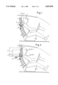
- FIG. 1 shows a simplified drawing to show the principle of the vehicle seat of the invention in a partly sectioned view in the position of use;
- FIG. 2 shows the vehicle seat of FIG. 1 in a rear end crash
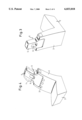
- FIG. 3 shows the vehicle seat of FIG. 1 in a perspective view looking obliquely from the rear;
- FIG. 4 shows the vehicle seat of FIG. 1 in a perspective view looking obliquely from the front;
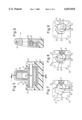
- FIG. 5 shows a longitudinal section taken through the upper part of the vehicle seat headrest
- FIG. 6 is a sectional view taken on the line X--X of FIG. 5;
- FIG. 7 is a side elevation of a bearing of the headrest in accordance with a first embodiment
- FIG. 8 is a side elevation of the bearing of the headrest in accordance with a second embodiment
- FIG. 9 is a side elevation of the bearing of the headrest in accordance with a third embodiment.
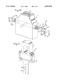
- FIG. 10 is an exploded view of the headrest and backrest part of the bearing in accordance with FIG. 9;
- FIG. 11 shows a headrest together with the backrest part mounted on a U-like shaped, vertically adjustable support.
- vehicle seat 2 for a vehicle occupant 1 is to be seen in the normal position of use, i.e. in the travelling position.
- the vehicle seat 2 comprises a backrest part 3 with a headrest 5, which is connected with a pivot pin 11 which, as is to be more clearly seen in FIG. 5, is pivotally mounted in a top terminal portion of the backrest by means of two bearings 13 for pivoting movement.
- a part (termed the backrest part 7 in what follows) which is separate from the rest of the backrest 3 has an upper backrest part forming a shoulder support.
- the headrest 5 and the separate backrest part 7 are cushioned to be harder than the remaining backrest 3 so that direct force transmission and rapid setting of the headrest is rendered possible as will be described hereinafter.
- the backrest part 7 is made integrally with the headrest 5 and the pivot pin 11 is arranged between the headrest 5 and the shoulder support so that a two-armed lever 9 is formed by the headrest 5 and the shoulder support.
- the two-armed lever 9 is able to be pivoted about the axis of the pivot pin 11.
- the headrest In the normal position of use depicted in FIG. 1, the headrest is at a distance X from the head of the occupant 1, such distance being approximately equal to the distance occurring with vehicle seats so far in use.
- the shoulder of the occupant 1 is at a smaller distance Y from the backrest part 7.
- the masses of the two-armed lever 9 and the position of the pivot pin 11 are so matched to one another that the pivot pin 11 extends through the center of gravity of the lever 9.
- the cushion parts are provided with teeth in this region, so as to interlock with each other as shown in FIG. 4 in broken lines.
- the headrest 5 may, as also shown in FIG. 4 in broken lines, have laterally projecting beads 4 and can be provided with an aperture 6 as is also illustrated in FIG. 4.
- a return spring 49 in the form of a strip spring pressing on the rear side of the backrest part 7 and urging the backrest part 7 against a lateral stop member.
- a damper 71 is arranged on the rear side of the backrest part 7 in order to act during pivoting of the lever 9.
- the two-armed lever 9 is made up of several layers and comprises a robust skeleton 55 having a transverse hole through which the pivot pin 11 extends.
- a pin 63 connects the skeleton 55 with the pivot pin 11 in a manner to prevent relative rotation.
- the skeleton 55 is surrounded by a cushion 57, preferably produced by foaming around it.
- the skeleton 55 is partly in the form of stiffening ribs in order to reduce weight.
- FIGS. 7 through 9 show various different possible forms of bearings for the pivot pin 11.
- one side of the backrest 3 it is possible for example for one side of the backrest 3 to have a rotary bearing and for the other side to accordingly have a bearing 13, 13' and 13" as shown in FIGS. 7 through 9, in which respect, however, it is an advantage if both sides have the same bearing design.
- FIGS. 7 through 9 the position of the pivot pin 11 within the bearing 13, 13' and 13" is illustrated in the normal position of use.
- the bearing 13 in accordance with FIG. 7 has a bearing opening 15 with a front cylindrical section 19 and an adjoining well 17, tapering with a small taper or wedge angle so that the pivot pin 11 may be jammed or gripped in the well 17.
- the center line of the well 17 in this case extends upwardly at an angle ⁇ to the horizontal.
- a shear pin 41 extends through the bearing 13 and fits into the pivot pin 11 preventing same from rotating.
- the free ends of the pivot pin 11 each possess an extension with a smaller diameter, against which a respective biasing device in the form of a spring 35--here a flat spring--urges.
- the spring 35 fits into a suitable groove 36 and is crimped in place therein, it serving to hold the pivot pin 11, which in the design of FIG. 5 is completely cylindrical, in the cylindrical section 19 of the bearing opening 15 so that a non-actuated setting is defined.
- the bearing opening 15 here also has a cylindrical section 19 which is adjoined by a well, said well, however, having a toothed section 23.
- the pivot pin 11 does not have any completely cylindrical circumferential surface, as is illustrated in FIG. 7, and instead simply has a cylindrical section 27 which is adjoined by a section 25 with a toothed outline representing a complementary outline for cooperation with the teeth of section 23.
- the bearing 13" illustrated in FIG. 9 is generally the same as the bearing 13' depicted in FIG. 8, there being a ratchet-like connection 43 instead of the shear pin 41, such connection 43 having a saw-tooth projection 45 on the bearing side fitting into a pit 47 in the pivot pin 11 which is formed complementary to it.
- the projection 45 and the pit 47 are so designed that the pivot pin 11 is able to be pivoted in a direction P whereas it is locked in the opposite direction.
- the injury-reducing effect of the vehicle seat 2 in a rear end crash will now be explained.
- the vehicle seat 2 will be in the position of use depicted in FIG. 1, holding means in the form of the return spring 49, the shear pin 41 or the ratchet-like connection 43, serving to restrain the lever 9 on pivoting in the position of use.
- the spring 35 cooperates to hold the lever 9 in the position of use.
- the ratio l1:l2 of lever arms l1 and l2 is in a range of 2.5:1 to 6:1 and preferably in a range between 4:1 and 6:1, since the ratio between the mass of the occupant's head and the proportional part of the occupant's shoulders is in a range of 1:4 and 1:6 for most people.
- the ratio of the length l3 of the headrest 5 to the length l4 of the backrest part is preferably in a range between 2.5:1 and 6:1. Whether equilibrium occurs at the lever 9 depends, however, more particularly on the position of the pivot pin 11.
- the lever arms l1 and l2 can be adapted to the respective user.
- the headrest 5 is for this purpose borne in a U-like carrier 61, which possesses a tongue 65 with a plurality of equally spaced holes 67, the tongue 65 being received in a corresponding bearing in the backrest 3, a releasable ratchet pawl device (not illustrated) fitting into the individual holes 67 for adjustment of the height of the headrest 5 and accordingly of the entire lever 9.
- FIG. 7 shows a means for this purpose for producing a frictional force constituted by the well 17.
- the toothed section 23 and the section 25 constitute a means for producing an interlocking connection to exclude any possibility of pivoting of the lever 9 in the actuated position of the means. If there is a rear end crash the pivot pin 11 will be shifted to the rear in relation to the vehicle after the pivot pin has turned while supported in its cylindrical section 27 so that the teeth in section 25 will mesh with the cooperating teeth on the section 23 of the bearing 13'. In this actuated position, lever 9 will be in a locked state.
- the bearing 13" in accordance with FIG. 9 allows manually resetting the pivot pin 11 in its original position after a minor accident.
- the projection 45 is namely not shorn off on rotation in the direction P.
- pivot pin 11 does not have to be splined or toothed for half of its periphery as illustrated in FIG. 8 since it would be sufficient to have only a few teeth on the periphery.
- the headrest 5 can be suitably softly cushioned.
- the return spring 49 can serve, in this case, like an additional damping means to reduce impact just like the separate damper 71. Additionally it is possible by having a higher moment of friction at the pivot pin 11 to produce the same effect, this being done by having a larger diameter of the extensions of the pivot pin 11 into which the springs 35 fit.
Landscapes
- Engineering & Computer Science (AREA)
- Aviation & Aerospace Engineering (AREA)
- Transportation (AREA)
- Mechanical Engineering (AREA)
- Seats For Vehicles (AREA)
- Vehicle Waterproofing, Decoration, And Sanitation Devices (AREA)
- Chairs For Special Purposes, Such As Reclining Chairs (AREA)
Applications Claiming Priority (2)
| Application Number | Priority Date | Filing Date | Title |
|---|---|---|---|
| DE29601479U DE29601479U1 (de) | 1996-01-29 | 1996-01-29 | Fahrzeugsitz |
| DE29601479U | 1996-01-29 |
Publications (1)
| Publication Number | Publication Date |
|---|---|
| US6033018A true US6033018A (en) | 2000-03-07 |
Family
ID=8018669
Family Applications (1)
| Application Number | Title | Priority Date | Filing Date |
|---|---|---|---|
| US08/786,871 Expired - Fee Related US6033018A (en) | 1996-01-29 | 1997-01-23 | Vehicle seat |
Country Status (7)
| Country | Link |
|---|---|
| US (1) | US6033018A (fr) |
| EP (1) | EP0786373A3 (fr) |
| JP (1) | JP2843801B2 (fr) |
| KR (1) | KR100232765B1 (fr) |
| CZ (1) | CZ22597A3 (fr) |
| DE (1) | DE29601479U1 (fr) |
| ES (1) | ES2109900T1 (fr) |
Cited By (31)
| Publication number | Priority date | Publication date | Assignee | Title |
|---|---|---|---|---|
| US6179379B1 (en) * | 1996-09-06 | 2001-01-30 | Autoliv Development Ab | Safety seat |
| US6416126B1 (en) * | 1997-09-10 | 2002-07-09 | Autoliv Development Ab | Vehicle seat |
| US6435592B2 (en) | 1997-03-11 | 2002-08-20 | Autoliv Development Ab | Device for avoiding whiplash injuries |
| US6435591B1 (en) * | 1997-03-11 | 2002-08-20 | Autoliv Development Ab | Device for avoiding whiplash injuries |
| GB2373177A (en) * | 2001-03-15 | 2002-09-18 | Autoliv Dev | Improvements in or relating to a vehicle seat safety arrangement |
| US6478373B1 (en) * | 1999-08-17 | 2002-11-12 | Johnson Controls Technology Company | Automotive seat—seat back with integrated protective device and process to prevent injuries caused by accident |
| US6511130B2 (en) * | 2000-03-16 | 2003-01-28 | Daimlerchrysler Ag | Head restraint for a vehicle seat |
| US6604788B1 (en) | 1998-12-14 | 2003-08-12 | Lear Corporation | Vehicle pivotal headrest |
| US6739654B1 (en) * | 2003-04-24 | 2004-05-25 | Hexa-Chain Co., Ltd. | Headrest-mount display mounting structure |
| US6749256B1 (en) | 2003-09-08 | 2004-06-15 | Lear Corporation | Vehicle seat having a movable head restraint |
| US20040155496A1 (en) * | 2003-02-06 | 2004-08-12 | Farquhar Mark A. | Anti-backdriving active head restraint |
| US20040160094A1 (en) * | 2003-02-18 | 2004-08-19 | Ford Global Technologies, Inc. | A vehicular seat assembly having a movable headrest and a vehicle which incorporates the vehicular seat assembly |
| US6789846B2 (en) | 2002-12-20 | 2004-09-14 | Lear Corporation | Vehicle seat having a movable head restraint |
| US20040195888A1 (en) * | 2003-04-03 | 2004-10-07 | Johnson Controls Technology Company | Configurable vehicle seat |
| US20040245840A1 (en) * | 2002-09-12 | 2004-12-09 | Tubergen Renard G. | Seating with comfort surface |
| US20050093349A1 (en) * | 2003-10-29 | 2005-05-05 | Lear Corporation | Akjustable head restraint or headrest |
| US20050179305A1 (en) * | 2004-02-12 | 2005-08-18 | Faurecia Autositze Gmbh & Co., Kg | Automobile seat |
| US20060138817A1 (en) * | 2004-12-29 | 2006-06-29 | Gorman Patrick J | Energy absorbing seat recliner assembly |
| US20060163930A1 (en) * | 2004-12-28 | 2006-07-27 | Pettersson Erik O | Head restraint system |
| US20060186713A1 (en) * | 1997-12-17 | 2006-08-24 | Automotive Technologies International, Inc. | Rear Impact Occupant Protection Apparatus and Method |
| US20060226686A1 (en) * | 2005-03-22 | 2006-10-12 | Shihong Yu | Spinal protection system for automotive seat |
| US20070057559A1 (en) * | 2005-09-14 | 2007-03-15 | Mazda Motor Corporation | Seat for vehicle |
| US20080001447A1 (en) * | 2006-06-08 | 2008-01-03 | Lear Corporation | Actuatable back panel for a vehicle seat |
| US20080030061A1 (en) * | 2006-08-04 | 2008-02-07 | Srinivas Pejathaya | Multi-position adjustment mechanism |
| US20080042483A1 (en) * | 2006-08-21 | 2008-02-21 | Lear Corporation | Moveable back panel for a vehicle seat |
| US7422280B2 (en) | 2006-04-07 | 2008-09-09 | Windsor Machine & Stamping Limited | Foldable headrest assembly |
| US20080246264A1 (en) * | 2007-04-05 | 2008-10-09 | Gerfast Sten R | In-expensive head and upper torso restraint with U-shaped air bag |
| US20100026061A1 (en) * | 2008-07-30 | 2010-02-04 | Trw Vehicle Safety Systems Inc. | Active head restraint for a vehicle seat |
| GB2494531A (en) * | 2011-09-08 | 2013-03-13 | Wonderland Nursery Goods | Child safety seat with headrest |
| US20150246628A1 (en) * | 2012-09-25 | 2015-09-03 | Toyota Jidosha Kabushiki Kaisha | Headrest and vehicle seat provided therewith, and method of manufacturing headrest |
| US9327682B2 (en) * | 2012-05-02 | 2016-05-03 | Kyungpook National University Industry-Academic Cooperation Foundation | Safety belt system for vehicle seats |
Families Citing this family (18)
| Publication number | Priority date | Publication date | Assignee | Title |
|---|---|---|---|---|
| DE29614238U1 (de) * | 1996-08-16 | 1996-12-12 | Trw Occupant Restraint Systems Gmbh, 73551 Alfdorf | Kopfstütze für einen Fahrzeugsitz |
| DE19643977C2 (de) * | 1996-10-31 | 2000-03-30 | Keiper Gmbh & Co | Fahrzeugsitz mit Multifunktionslehne |
| DE19731059A1 (de) * | 1997-07-19 | 1999-01-21 | Opel Adam Ag | Aktive Kopfstütze, insbesondere für einen Kraftfahrzeugsitz |
| DE19704974C2 (de) * | 1997-01-28 | 2002-11-07 | Rolf Willer | Kragenkopfstütze |
| DE19754311B4 (de) * | 1997-06-10 | 2007-09-06 | Ewald Witte Gmbh & Co Kg | Rückenlehne mit Kopfstütze an Fahrzeugsitzen |
| DE29808831U1 (de) * | 1998-05-15 | 1998-08-27 | Delphi Automotive Systems Deutschland GmbH, 42369 Wuppertal | Sitz- und Kopfstützenanordnung für ein Fahrzeug |
| DE19825701A1 (de) | 1998-06-09 | 1999-12-16 | Volkswagen Ag | Fahrzeugsitz mit begrenzter Rückverlagerung von Sitzkomponenten unter Energieabsorption bei einem Heckaufprall |
| DE19910666A1 (de) | 1999-03-11 | 2000-09-14 | Volkswagen Ag | Sitz für einen Insassen eines Kraftfahrzeuges |
| US6129421A (en) * | 1999-08-05 | 2000-10-10 | Lear Corporation | Foldable halo style headrest |
| DE19946404C2 (de) * | 1999-09-28 | 2003-10-30 | Siemens Restraint Systems Gmbh | System zur schlagartigen Reduzierung des Abstandes zwischen Kopfstütze und Kopf eines Fahrzeuginsassen |
| DE19957194B4 (de) * | 1999-11-27 | 2009-02-05 | Volkswagen Ag | Fahrzeugsitz |
| DE10013325B4 (de) * | 2000-03-10 | 2012-06-21 | Volkswagen Ag | Fahrzeugsitz mit einer Kopfstütze |
| DE10033913B4 (de) * | 2000-07-05 | 2009-07-09 | Volkswagen Ag | Kopfstütze für einen Fahrzeugsitz, insbesondere für einen Kraftfahrzeugsitz |
| JP4492439B2 (ja) * | 2004-06-16 | 2010-06-30 | トヨタ紡織株式会社 | ヘッドレスト |
| FR2901199B1 (fr) * | 2006-05-19 | 2009-04-03 | Peugeot Citroen Automobiles Sa | Dossier de siege comprenant un appuie-tete mobile en rotation |
| DE102007041521A1 (de) * | 2007-08-31 | 2009-03-05 | Johnson Controls Gmbh | Kopfstütze für ein Fahrzeug |
| FR2995265B1 (fr) * | 2012-09-11 | 2015-06-19 | Renault Sa | Siege de vehicule resistant a un choc de bagage |
| JP6763790B2 (ja) * | 2017-01-12 | 2020-09-30 | トヨタ紡織株式会社 | ヘッドレスト |
Citations (9)
| Publication number | Priority date | Publication date | Assignee | Title |
|---|---|---|---|---|
| US2973029A (en) * | 1958-06-16 | 1961-02-28 | Clifford F Schlosstein | Passenger safety equipment for automobile |
| US3802737A (en) * | 1972-07-07 | 1974-04-09 | Heizer K | Safety seat, particularly for automotive vehicles |
| US3838870A (en) * | 1972-02-10 | 1974-10-01 | Gen Motors Corp | Motor vehicles bodies |
| US3866723A (en) * | 1973-11-12 | 1975-02-18 | Elmer M Smith | Safety device for actuating a brake |
| GB1483567A (en) * | 1974-06-26 | 1977-08-24 | Ford Motor Co | Head-rest for motor vehicles |
| US4335918A (en) * | 1980-09-10 | 1982-06-22 | Bsg International Limited | Vehicle safety seat |
| US5181763A (en) * | 1990-09-20 | 1993-01-26 | Ronald P. Dellanno | Apparatus for preventing whiplash |
| EP0627340A1 (fr) * | 1993-06-01 | 1994-12-07 | General Motors Corporation | Appui-tête pivotable pour véhicules |
| JPH07291005A (ja) * | 1994-04-27 | 1995-11-07 | Daihatsu Motor Co Ltd | 自動車用シート |
Family Cites Families (4)
| Publication number | Priority date | Publication date | Assignee | Title |
|---|---|---|---|---|
| JPS5211515B2 (fr) * | 1972-07-03 | 1977-03-31 | ||
| JPS4939710U (fr) * | 1972-07-11 | 1974-04-08 | ||
| JPS4934535A (fr) * | 1972-08-02 | 1974-03-30 | ||
| JPS643408Y2 (fr) * | 1980-11-20 | 1989-01-30 |
-
1996
- 1996-01-29 DE DE29601479U patent/DE29601479U1/de not_active Expired - Lifetime
-
1997
- 1997-01-20 EP EP97100805A patent/EP0786373A3/fr not_active Withdrawn
- 1997-01-20 ES ES97100805T patent/ES2109900T1/es active Pending
- 1997-01-23 US US08/786,871 patent/US6033018A/en not_active Expired - Fee Related
- 1997-01-24 CZ CZ97225A patent/CZ22597A3/cs unknown
- 1997-01-27 KR KR1019970002234A patent/KR100232765B1/ko not_active Expired - Fee Related
- 1997-01-28 JP JP9014181A patent/JP2843801B2/ja not_active Expired - Lifetime
Patent Citations (11)
| Publication number | Priority date | Publication date | Assignee | Title |
|---|---|---|---|---|
| US2973029A (en) * | 1958-06-16 | 1961-02-28 | Clifford F Schlosstein | Passenger safety equipment for automobile |
| US3838870A (en) * | 1972-02-10 | 1974-10-01 | Gen Motors Corp | Motor vehicles bodies |
| US3802737A (en) * | 1972-07-07 | 1974-04-09 | Heizer K | Safety seat, particularly for automotive vehicles |
| US3866723A (en) * | 1973-11-12 | 1975-02-18 | Elmer M Smith | Safety device for actuating a brake |
| GB1483567A (en) * | 1974-06-26 | 1977-08-24 | Ford Motor Co | Head-rest for motor vehicles |
| US4335918A (en) * | 1980-09-10 | 1982-06-22 | Bsg International Limited | Vehicle safety seat |
| US5181763A (en) * | 1990-09-20 | 1993-01-26 | Ronald P. Dellanno | Apparatus for preventing whiplash |
| US5290091A (en) * | 1990-09-20 | 1994-03-01 | Dellanno Ronald P | Apparatus for preventing whiplash |
| EP0627340A1 (fr) * | 1993-06-01 | 1994-12-07 | General Motors Corporation | Appui-tête pivotable pour véhicules |
| US5378043A (en) * | 1993-06-01 | 1995-01-03 | General Motors Corporation | Vehicle pivotal headrest |
| JPH07291005A (ja) * | 1994-04-27 | 1995-11-07 | Daihatsu Motor Co Ltd | 自動車用シート |
Cited By (65)
| Publication number | Priority date | Publication date | Assignee | Title |
|---|---|---|---|---|
| US6179379B1 (en) * | 1996-09-06 | 2001-01-30 | Autoliv Development Ab | Safety seat |
| US6435591B1 (en) * | 1997-03-11 | 2002-08-20 | Autoliv Development Ab | Device for avoiding whiplash injuries |
| US6435592B2 (en) | 1997-03-11 | 2002-08-20 | Autoliv Development Ab | Device for avoiding whiplash injuries |
| US6767054B2 (en) | 1997-09-10 | 2004-07-27 | Autoliv Development Ab | Vehicle seat |
| US20030001415A1 (en) * | 1997-09-10 | 2003-01-02 | Yngve Haland | Vehicle seat |
| US6416126B1 (en) * | 1997-09-10 | 2002-07-09 | Autoliv Development Ab | Vehicle seat |
| US20080042418A1 (en) * | 1997-12-17 | 2008-02-21 | Automotive Technologies International, Inc. | Rear Impact Occupant Protection Apparatus and Method |
| US20060186713A1 (en) * | 1997-12-17 | 2006-08-24 | Automotive Technologies International, Inc. | Rear Impact Occupant Protection Apparatus and Method |
| US7695015B2 (en) * | 1997-12-17 | 2010-04-13 | Automotive Technologies International, Inc. | Rear impact occupant protection apparatus and method |
| US7604080B2 (en) * | 1997-12-17 | 2009-10-20 | Automotive Technologies International, Inc. | Rear impact occupant protection apparatus and method |
| US7588115B2 (en) | 1997-12-17 | 2009-09-15 | Automotive Technologies International, Inc. | System and method for moving a headrest for whiplash prevention |
| US6604788B1 (en) | 1998-12-14 | 2003-08-12 | Lear Corporation | Vehicle pivotal headrest |
| US6478373B1 (en) * | 1999-08-17 | 2002-11-12 | Johnson Controls Technology Company | Automotive seat—seat back with integrated protective device and process to prevent injuries caused by accident |
| US20050035642A1 (en) * | 1999-08-17 | 2005-02-17 | Johnson Controls Technology Company | Seat back for a vehicle seat comprising an integrated protective device |
| US6802562B1 (en) | 1999-08-17 | 2004-10-12 | Johnson Controls Technology Company | Seat back for a vehicle seat comprising an integrated protective device |
| US6511130B2 (en) * | 2000-03-16 | 2003-01-28 | Daimlerchrysler Ag | Head restraint for a vehicle seat |
| US20040245833A1 (en) * | 2001-03-15 | 2004-12-09 | Anders Svantesson | Safety headrest for a motor vehicle |
| GB2373177A (en) * | 2001-03-15 | 2002-09-18 | Autoliv Dev | Improvements in or relating to a vehicle seat safety arrangement |
| US6983996B2 (en) | 2001-03-15 | 2006-01-10 | Autoliv Development Ab | Safety headrest for a motor vehicle |
| GB2373177B (en) * | 2001-03-15 | 2004-04-28 | Autoliv Dev | Improvements in or relating to a safety arrangement |
| US7360835B2 (en) | 2002-09-12 | 2008-04-22 | Steelcase Inc. | Seating with comfort surface |
| US20040245840A1 (en) * | 2002-09-12 | 2004-12-09 | Tubergen Renard G. | Seating with comfort surface |
| US20070228800A1 (en) * | 2002-09-12 | 2007-10-04 | Tubergen Renard G | Seating with comfort surface |
| US7226130B2 (en) | 2002-09-12 | 2007-06-05 | Steelcase Development Corporation | Seating with comfort surface |
| US6789846B2 (en) | 2002-12-20 | 2004-09-14 | Lear Corporation | Vehicle seat having a movable head restraint |
| US7097242B2 (en) | 2003-02-06 | 2006-08-29 | Lear Corporation | Anti-backdriving active head restraint |
| US20040155496A1 (en) * | 2003-02-06 | 2004-08-12 | Farquhar Mark A. | Anti-backdriving active head restraint |
| US6840560B2 (en) * | 2003-02-18 | 2005-01-11 | Ford Global Technologies, Llc | Vehicular seat assembly having a movable headrest and a vehicle which incorporates the vehicular seat assembly |
| US20040160094A1 (en) * | 2003-02-18 | 2004-08-19 | Ford Global Technologies, Inc. | A vehicular seat assembly having a movable headrest and a vehicle which incorporates the vehicular seat assembly |
| US20040195888A1 (en) * | 2003-04-03 | 2004-10-07 | Johnson Controls Technology Company | Configurable vehicle seat |
| US6739654B1 (en) * | 2003-04-24 | 2004-05-25 | Hexa-Chain Co., Ltd. | Headrest-mount display mounting structure |
| US6749256B1 (en) | 2003-09-08 | 2004-06-15 | Lear Corporation | Vehicle seat having a movable head restraint |
| US6942292B2 (en) * | 2003-10-29 | 2005-09-13 | Lear Corporation | Adjustable head restraint or headrest |
| US20050093349A1 (en) * | 2003-10-29 | 2005-05-05 | Lear Corporation | Akjustable head restraint or headrest |
| US20050179305A1 (en) * | 2004-02-12 | 2005-08-18 | Faurecia Autositze Gmbh & Co., Kg | Automobile seat |
| US7325869B2 (en) * | 2004-02-12 | 2008-02-05 | Volkswagen Ag | Automobile seat |
| US7185950B2 (en) | 2004-12-28 | 2007-03-06 | Fisher Dynamics Corporation | Head restraint system |
| US20060163930A1 (en) * | 2004-12-28 | 2006-07-27 | Pettersson Erik O | Head restraint system |
| US20060138817A1 (en) * | 2004-12-29 | 2006-06-29 | Gorman Patrick J | Energy absorbing seat recliner assembly |
| US20060226686A1 (en) * | 2005-03-22 | 2006-10-12 | Shihong Yu | Spinal protection system for automotive seat |
| US20070057559A1 (en) * | 2005-09-14 | 2007-03-15 | Mazda Motor Corporation | Seat for vehicle |
| US7559608B2 (en) * | 2005-09-14 | 2009-07-14 | Mazda Motor Corporation | Seat for vehicle |
| US7422280B2 (en) | 2006-04-07 | 2008-09-09 | Windsor Machine & Stamping Limited | Foldable headrest assembly |
| US7401852B2 (en) | 2006-06-08 | 2008-07-22 | Lear Corporation | Actuatable back panel for a vehicle seat |
| US20080001447A1 (en) * | 2006-06-08 | 2008-01-03 | Lear Corporation | Actuatable back panel for a vehicle seat |
| US20080030061A1 (en) * | 2006-08-04 | 2008-02-07 | Srinivas Pejathaya | Multi-position adjustment mechanism |
| US7549699B2 (en) | 2006-08-21 | 2009-06-23 | Lear Corporation | Moveable back panel for a vehicle seat |
| US7959225B2 (en) | 2006-08-21 | 2011-06-14 | Lear Corporation | Moveable back panel for a vehicle seat |
| US20090184546A1 (en) * | 2006-08-21 | 2009-07-23 | Lear Corporation | Moveable Back Panel for a Vehicle Seat |
| US20080042483A1 (en) * | 2006-08-21 | 2008-02-21 | Lear Corporation | Moveable back panel for a vehicle seat |
| US7819470B2 (en) | 2006-08-21 | 2010-10-26 | Lear Corporation | Moveable back panel for a vehicle seat |
| US20110018318A1 (en) * | 2006-08-21 | 2011-01-27 | Lear Corporation | Moveable back panel for a vehicle seat |
| US7445284B2 (en) * | 2007-04-05 | 2008-11-04 | Gerfast Sten R | In-expensive head and upper torso restraint with u-shaped air bag |
| US20080246264A1 (en) * | 2007-04-05 | 2008-10-09 | Gerfast Sten R | In-expensive head and upper torso restraint with U-shaped air bag |
| US8205941B2 (en) | 2008-07-30 | 2012-06-26 | Trw Vehicle Safety Systems Inc. | Active head restraint for a vehicle seat |
| US20100026061A1 (en) * | 2008-07-30 | 2010-02-04 | Trw Vehicle Safety Systems Inc. | Active head restraint for a vehicle seat |
| GB2494531A (en) * | 2011-09-08 | 2013-03-13 | Wonderland Nursery Goods | Child safety seat with headrest |
| US20140312666A1 (en) * | 2011-09-08 | 2014-10-23 | Chin-Ming Cheng | Child safety seat |
| US8931836B2 (en) | 2011-09-08 | 2015-01-13 | Wonderland Nurserygoods Company Limited | Child safety seat |
| DE102012017746B4 (de) * | 2011-09-08 | 2016-06-30 | Wonderland Nurserygoods Company Limited | Kindersicherheitssitz |
| US9511697B2 (en) * | 2011-09-08 | 2016-12-06 | Wonderland Nurserygoods Company Limited | Child safety seat |
| GB2494531B (en) * | 2011-09-08 | 2018-04-11 | Wonderland Switzerland Ag | A child safety seat comprising a headrest insertion slot with an elastic cushion |
| US9327682B2 (en) * | 2012-05-02 | 2016-05-03 | Kyungpook National University Industry-Academic Cooperation Foundation | Safety belt system for vehicle seats |
| US20150246628A1 (en) * | 2012-09-25 | 2015-09-03 | Toyota Jidosha Kabushiki Kaisha | Headrest and vehicle seat provided therewith, and method of manufacturing headrest |
| US9539923B2 (en) * | 2012-09-25 | 2017-01-10 | Toyota Jidosha Kabushiki Kaisha | Headrest and vehicle seat provided therewith, and method of manufacturing headrest |
Also Published As
| Publication number | Publication date |
|---|---|
| KR100232765B1 (ko) | 1999-12-01 |
| KR970058988A (ko) | 1997-08-12 |
| EP0786373A2 (fr) | 1997-07-30 |
| EP0786373A3 (fr) | 1998-08-19 |
| CZ22597A3 (en) | 1997-08-13 |
| DE29601479U1 (de) | 1996-05-30 |
| ES2109900T1 (es) | 1998-02-01 |
| JP2843801B2 (ja) | 1999-01-06 |
| JPH09220956A (ja) | 1997-08-26 |
Similar Documents
| Publication | Publication Date | Title |
|---|---|---|
| US6033018A (en) | Vehicle seat | |
| US6398299B1 (en) | Motor vehicle seat with a back rest | |
| US6135561A (en) | Seat back with headrest on vehicle seats | |
| JP5049790B2 (ja) | シートの背もたれ支持機構 | |
| US8240736B2 (en) | Deceleration responsive vehicle seat | |
| CN102282040B (zh) | 乘坐物用座椅 | |
| US6082817A (en) | Motor vehicle seat | |
| US6352312B1 (en) | Vehicle seat interlock | |
| EP1953035B1 (fr) | Siège enfant | |
| US6394535B1 (en) | Vehicle occupant protection system | |
| JP2005186670A (ja) | 車両用シート | |
| US6957858B2 (en) | Dynamic flip-up head restraint | |
| US20190299825A1 (en) | Longitudinal adjuster and vehicle seat | |
| US6840560B2 (en) | Vehicular seat assembly having a movable headrest and a vehicle which incorporates the vehicular seat assembly | |
| US20040183344A1 (en) | Seat energy absorber | |
| KR20030015025A (ko) | 자동차의 서브마린 방지용 패널 구조 | |
| JP2003040013A (ja) | 車両のシート構造 | |
| CN1162540A (zh) | 车辆座位 | |
| JP7716121B2 (ja) | ヘッドレスト | |
| EP0692402A2 (fr) | Système de retenue passif | |
| WO2009005463A1 (fr) | Système d'alerte haptique pour véhicule à moteur | |
| US10252648B2 (en) | Inertia driven rotatable upper seat portion for rear passenger head clearance | |
| JP5023586B2 (ja) | 車両の後部車体構造 | |
| JP6565311B2 (ja) | 乗物用シート | |
| US20250276623A1 (en) | Crash device for a vehicle seat |
Legal Events
| Date | Code | Title | Description |
|---|---|---|---|
| AS | Assignment |
Owner name: TRW OCCUPANT RESTRAINT SYSTEMS GMBH, GERMANY Free format text: ASSIGNMENT OF ASSIGNORS INTEREST;ASSIGNOR:FOHL, ARTUR;REEL/FRAME:008405/0138 Effective date: 19970108 |
|
| REMI | Maintenance fee reminder mailed | ||
| LAPS | Lapse for failure to pay maintenance fees | ||
| FP | Lapsed due to failure to pay maintenance fee |
Effective date: 20040307 |
|
| STCH | Information on status: patent discontinuation |
Free format text: PATENT EXPIRED DUE TO NONPAYMENT OF MAINTENANCE FEES UNDER 37 CFR 1.362 |