US6033038A - Brake control method having booster runout and pedal force estimation - Google Patents
Brake control method having booster runout and pedal force estimation Download PDFInfo
- Publication number
- US6033038A US6033038A US09/102,113 US10211398A US6033038A US 6033038 A US6033038 A US 6033038A US 10211398 A US10211398 A US 10211398A US 6033038 A US6033038 A US 6033038A
- Authority
- US
- United States
- Prior art keywords
- pressure
- vacuum
- force
- apply
- brake
- Prior art date
- Legal status (The legal status is an assumption and is not a legal conclusion. Google has not performed a legal analysis and makes no representation as to the accuracy of the status listed.)
- Expired - Lifetime
Links
- 238000000034 method Methods 0.000 title claims abstract description 19
- 230000003190 augmentative effect Effects 0.000 claims abstract description 5
- 230000014509 gene expression Effects 0.000 claims description 21
- 238000001514 detection method Methods 0.000 claims description 5
- 230000003068 static effect Effects 0.000 claims description 5
- 230000003213 activating effect Effects 0.000 claims 2
- 238000013178 mathematical model Methods 0.000 abstract description 3
- 238000006243 chemical reaction Methods 0.000 description 8
- 238000010586 diagram Methods 0.000 description 8
- 238000006073 displacement reaction Methods 0.000 description 4
- 230000003321 amplification Effects 0.000 description 3
- 238000004364 calculation method Methods 0.000 description 3
- 239000012530 fluid Substances 0.000 description 3
- 230000010354 integration Effects 0.000 description 3
- 238000003199 nucleic acid amplification method Methods 0.000 description 3
- 230000000153 supplemental effect Effects 0.000 description 3
- 230000009977 dual effect Effects 0.000 description 2
- 102100025588 Calcitonin gene-related peptide 1 Human genes 0.000 description 1
- 102100038521 Calcitonin gene-related peptide 2 Human genes 0.000 description 1
- 101000741445 Homo sapiens Calcitonin Proteins 0.000 description 1
- 101000932890 Homo sapiens Calcitonin gene-related peptide 1 Proteins 0.000 description 1
- 101000741431 Homo sapiens Calcitonin gene-related peptide 2 Proteins 0.000 description 1
- 238000007796 conventional method Methods 0.000 description 1
- 239000000463 material Substances 0.000 description 1
- 230000013011 mating Effects 0.000 description 1
- 239000002184 metal Substances 0.000 description 1
- 238000012986 modification Methods 0.000 description 1
- 230000004048 modification Effects 0.000 description 1
- 230000002093 peripheral effect Effects 0.000 description 1
- 238000011144 upstream manufacturing Methods 0.000 description 1
Images


Classifications
-
- B—PERFORMING OPERATIONS; TRANSPORTING
- B60—VEHICLES IN GENERAL
- B60T—VEHICLE BRAKE CONTROL SYSTEMS OR PARTS THEREOF; BRAKE CONTROL SYSTEMS OR PARTS THEREOF, IN GENERAL; ARRANGEMENT OF BRAKING ELEMENTS ON VEHICLES IN GENERAL; PORTABLE DEVICES FOR PREVENTING UNWANTED MOVEMENT OF VEHICLES; VEHICLE MODIFICATIONS TO FACILITATE COOLING OF BRAKES
- B60T8/00—Arrangements for adjusting wheel-braking force to meet varying vehicular or ground-surface conditions, e.g. limiting or varying distribution of braking force
- B60T8/32—Arrangements for adjusting wheel-braking force to meet varying vehicular or ground-surface conditions, e.g. limiting or varying distribution of braking force responsive to a speed condition, e.g. acceleration or deceleration
- B60T8/34—Arrangements for adjusting wheel-braking force to meet varying vehicular or ground-surface conditions, e.g. limiting or varying distribution of braking force responsive to a speed condition, e.g. acceleration or deceleration having a fluid pressure regulator responsive to a speed condition
- B60T8/44—Arrangements for adjusting wheel-braking force to meet varying vehicular or ground-surface conditions, e.g. limiting or varying distribution of braking force responsive to a speed condition, e.g. acceleration or deceleration having a fluid pressure regulator responsive to a speed condition co-operating with a power-assist booster means associated with a master cylinder for controlling the release and reapplication of brake pressure through an interaction with the power assist device, i.e. open systems
- B60T8/441—Arrangements for adjusting wheel-braking force to meet varying vehicular or ground-surface conditions, e.g. limiting or varying distribution of braking force responsive to a speed condition, e.g. acceleration or deceleration having a fluid pressure regulator responsive to a speed condition co-operating with a power-assist booster means associated with a master cylinder for controlling the release and reapplication of brake pressure through an interaction with the power assist device, i.e. open systems using hydraulic boosters
- B60T8/442—Arrangements for adjusting wheel-braking force to meet varying vehicular or ground-surface conditions, e.g. limiting or varying distribution of braking force responsive to a speed condition, e.g. acceleration or deceleration having a fluid pressure regulator responsive to a speed condition co-operating with a power-assist booster means associated with a master cylinder for controlling the release and reapplication of brake pressure through an interaction with the power assist device, i.e. open systems using hydraulic boosters the booster being a fluid return pump, e.g. in combination with a brake pedal force booster
-
- B—PERFORMING OPERATIONS; TRANSPORTING
- B60—VEHICLES IN GENERAL
- B60T—VEHICLE BRAKE CONTROL SYSTEMS OR PARTS THEREOF; BRAKE CONTROL SYSTEMS OR PARTS THEREOF, IN GENERAL; ARRANGEMENT OF BRAKING ELEMENTS ON VEHICLES IN GENERAL; PORTABLE DEVICES FOR PREVENTING UNWANTED MOVEMENT OF VEHICLES; VEHICLE MODIFICATIONS TO FACILITATE COOLING OF BRAKES
- B60T13/00—Transmitting braking action from initiating means to ultimate brake actuator with power assistance or drive; Brake systems incorporating such transmitting means, e.g. air-pressure brake systems
- B60T13/10—Transmitting braking action from initiating means to ultimate brake actuator with power assistance or drive; Brake systems incorporating such transmitting means, e.g. air-pressure brake systems with fluid assistance, drive, or release
- B60T13/24—Transmitting braking action from initiating means to ultimate brake actuator with power assistance or drive; Brake systems incorporating such transmitting means, e.g. air-pressure brake systems with fluid assistance, drive, or release the fluid being gaseous
- B60T13/46—Vacuum systems
- B60T13/52—Vacuum systems indirect, i.e. vacuum booster units
- B60T13/563—Vacuum systems indirect, i.e. vacuum booster units with multiple booster units, e.g. tandem booster units
-
- B—PERFORMING OPERATIONS; TRANSPORTING
- B60—VEHICLES IN GENERAL
- B60T—VEHICLE BRAKE CONTROL SYSTEMS OR PARTS THEREOF; BRAKE CONTROL SYSTEMS OR PARTS THEREOF, IN GENERAL; ARRANGEMENT OF BRAKING ELEMENTS ON VEHICLES IN GENERAL; PORTABLE DEVICES FOR PREVENTING UNWANTED MOVEMENT OF VEHICLES; VEHICLE MODIFICATIONS TO FACILITATE COOLING OF BRAKES
- B60T13/00—Transmitting braking action from initiating means to ultimate brake actuator with power assistance or drive; Brake systems incorporating such transmitting means, e.g. air-pressure brake systems
- B60T13/10—Transmitting braking action from initiating means to ultimate brake actuator with power assistance or drive; Brake systems incorporating such transmitting means, e.g. air-pressure brake systems with fluid assistance, drive, or release
- B60T13/66—Electrical control in fluid-pressure brake systems
- B60T13/662—Electrical control in fluid-pressure brake systems characterised by specified functions of the control system components
-
- B—PERFORMING OPERATIONS; TRANSPORTING
- B60—VEHICLES IN GENERAL
- B60T—VEHICLE BRAKE CONTROL SYSTEMS OR PARTS THEREOF; BRAKE CONTROL SYSTEMS OR PARTS THEREOF, IN GENERAL; ARRANGEMENT OF BRAKING ELEMENTS ON VEHICLES IN GENERAL; PORTABLE DEVICES FOR PREVENTING UNWANTED MOVEMENT OF VEHICLES; VEHICLE MODIFICATIONS TO FACILITATE COOLING OF BRAKES
- B60T13/00—Transmitting braking action from initiating means to ultimate brake actuator with power assistance or drive; Brake systems incorporating such transmitting means, e.g. air-pressure brake systems
- B60T13/10—Transmitting braking action from initiating means to ultimate brake actuator with power assistance or drive; Brake systems incorporating such transmitting means, e.g. air-pressure brake systems with fluid assistance, drive, or release
- B60T13/66—Electrical control in fluid-pressure brake systems
- B60T13/68—Electrical control in fluid-pressure brake systems by electrically-controlled valves
- B60T13/686—Electrical control in fluid-pressure brake systems by electrically-controlled valves in hydraulic systems or parts thereof
Definitions
- This invention relates to electrically assisted vacuum boost braking systems, and more particularly to a control method for accurately detecting pedal force and a condition of vacuum booster run-out.
- a master cylinder converts driver exerted brake pedal force into a corresponding hydraulic pressure, which is proportioned among the front and rear brakes.
- a vacuum booster is interposed between the pedal and the master cylinder to amplify the force applied to the master cylinder.
- the vacuum booster has access to engine vacuum, and amplifies the driver exerted force by controlling the pressure differential across one or more diaphragms coupled to the master cylinder.
- a vacuum chamber disposed on the master cylinder side of the diaphragm is coupled to engine vacuum
- an apply chamber disposed on the brake pedal side of the diaphragm is coupled to a valve that varies the pressure in the chamber between engine vacuum and atmospheric pressure.
- the booster is said to reach a "run-out" condition when the apply chamber is at atmospheric pressure, since there can be no further amplification of the brake pedal force.
- the force amplification of the vacuum booster is modified and/or supplemented by an electrically controlled pressure modulator.
- Control of the modulator requires knowledge of the pedal force and the operating state of the vacuum booster, particularly whether the booster is operating in a run-out condition.
- the conventional approach in this regard is to use dedicated sensors for measuring the necessary parameters.
- a force sensor can be used to measure the pedal force
- a pressure sensor can be used to measure the apply chamber pressure, with an impending run-out condition being detected when the measured apply chamber pressure reaches atmospheric pressure.
- the present invention is directed to an improved electrically assisted brake control method in which vacuum booster run-out and pedal force are accurately predicted as a function of master cylinder pressure and engine vacuum, thereby eliminating the expense of additional dedicated sensors.
- a mathematical model of the vacuum booster is used to estimate at least the apply chamber pressure, and preferably, the operator brake pedal force, based on measured values of engine vacuum (or manifold absolute pressure) and master cylinder pressure.
- the point of vacuum booster runout can be detected as the point at which the estimated apply chamber pressure reaches atmospheric pressure.
- a force-balance approach is used to carry out the estimation in an accurate but simple manner that is especially amenable to real-time control in an automotive on-board micro-controller.
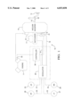
- FIG. 1 is a diagram of an electrically assisted brake control system according to this invention.
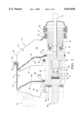
- FIG. 2 is a diagram of a conventional vacuum booster, as shown in FIG. 1.
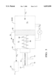
- FIG. 3 is a diagram of a model of the vacuum booster of FIG. 2.
- FIG. 4 is a block diagram of a runout detection and pedal force estimation technique according to a first embodiment of this invention.
- FIG. 5 is a force diagram for detecting runout and estimating pedal force in accordance with a second embodiment of this invention.
- FIG. 6 is a block diagram of a runout detection and pedal force estimation technique according to the second embodiment of this invention.
- FIG. 1 illustrates a brake system 10 in which an electrically operated modulator 20 supplies supplemental hydraulic braking pressure upon detection of vacuum booster runout.
- the brake system 10 includes a brake pedal 12 which provides a force input to the vacuum booster 14 through the push-rod 15. The force applied to the push-rod 15 by the pedal 12 is amplified by the vacuum booster 14 and is communicated to the master cylinder 16.
- the master cylinder 16 includes a fluid reservoir 17 for supplying the fluid needs of the brake system 10.
- the master cylinder 16 is of the conventional dual piston type wherein movement of the master cylinder pistons develops hydraulic pressure which is transmitted to a split braking system through brake lines 18 and 19. Brake lines 18 and 19 extend through a modulator 20 and branch into brake lines 21-24 which connect with the four wheel brakes 25-28.
- Modulator 20 is an electro-hydraulic device such as a motor operated piston for controllably modifying the master cylinder brake pressures distributed to the brake lines 21-24.
- An electronic controller 30 is provided for managing operation of the brake system 10.
- the controller 30 communicates with the modulator 20 and also with the engine manifold air pressure sensor 35 and the pressure sensor 31 which measures the fluid pressure in brake line 18 as generated by the master cylinder 16.
- Element 34 is a vacuum check valve which permits a one-way flow of air from the booster 14 to the manifold of engine 11.
- the controller 30 may also be provided with brake line pressure signals for the pressure at wheel brakes 25-28 through a conventional means.
- the controller 30 is capable of estimating the force applied to brake pedal 12 and detecting the point of vacuum booster runout. The detection of runout is used to activate the modulator 20 to supply supplemental brake pressure, and the estimated pedal force is used to control the modulator 20 so that the braking force varies linearly with pedal force in spite of the runout condition.
- FIG. 2 depicts the vacuum booster 14 of FIG. 1 in greater detail.
- vacuum booster 14 is a dual diaphragm vacuum operated booster in this exemplary embodiment, the present invention is also applicable to systems with a single diaphragm vacuum booster.
- FIG. 2 illustrates in cross section essentially half the vacuum booster 14 with the remaining unillustrated portion being substantially a mirror image for purposes of the present discussion.
- Vacuum booster 14 has a substantially open internal cavity which is formed by mating front housing 54 and rear housing 55.
- the front and rear housings 54 and 55 are formed from a conventional material such as metal or plastic.
- Rear housing 55 includes an axially extending flange 62 that mates with outer turned flange 68 of front housing 54 locking the housings 54, 55 together.
- An inner edge 56 of rear housing 55 carries a seal 57.
- the end of rear housing 55 is enclosed by boot 58 which is received over the inner edge 56.
- Another seal 59 seals the area at inner edge 63 of front housing 54. The seal 59 is secured between the rearward end of master cylinder 16, (seen in FIG. 1), and the front housing 54.
- a housing divider 70 separates the internal cavity into front and rear chambers 71 and 72, respectively.
- Housing divider 70 includes an outer peripheral flange which is engaged between the front housing 54 and rear housing 55.
- Housing divider 70 also includes an inner edge which carries an annular seal 77.
- a power piston 80 extends through annular seals 57 and 77, and is slidable forwardly and rearwardly within the annular seals 57 and 77.
- the annual seals 57 and 77 act as bearings for supporting the power piston 80 in the lateral direction.
- Power piston 80 includes a rearwardly directed wall 83 against which support plate 84 supports diaphragm 85.
- Diaphragm 85 includes an integral inner annular seal 89 which engages the power piston 80.
- Diaphragm 85 separates chamber 71 into vacuum chamber 87 and apply chamber 88.
- Power piston 80 also includes rearwardly directed wall 91 against which support plate 92 supports diaphragm 93.
- Diaphragm 93 includes an integral inner annular seal 94 which engages the power piston 80.
- Diaphragm 93 separates rear chamber 72 into vacuum chamber 95 and apply chamber 96.
- the diaphragms 85 and 93, and their respective support plates 84 and 92, are operable such that a vacuum pressure exists in vacuum chambers 87 and 95 which is generated therein through vacuum check valve 34 by the engine 11.
- the variable pressure in apply chambers 88 and 96 selectively creates a force on the respective diaphragms 85 and 93.
- the support plates 84 and 92 apply the force of the diaphragms 85 and 93 to the respective rearwardly directed walls 83 and 91 of power piston 80.
- power piston 80 compresses return spring 98 as shown, causing power piston 80 to slide within annular seals 77 and 78 forcing rod 99 to apply force to the master cylinder 16.
- variable pressure in apply chambers 88 and 96 is increased through operation of the air valve 60.
- Air valve 60 is illustrated in the open position which allows atmospheric pressure to enter the apply chambers 88 and 96 and thus creates a pressure differential across the diaphragms 85 and 93.
- the maximum pressure differential between vacuum chambers 87 and 95 on one hand and apply chambers 88 and 96 on the other hand, is the difference between engine vacuum and atmospheric pressure.
- Atmospheric air entering the vacuum booster 14 travels through filter 75 and the vacuum drawn from the vacuum booster 14 exits through vacuum check valve 34 which is received in the front housing 54.
- Power piston 80 includes a plurality of air passages through which flow is directed in a conventional manner.
- the vacuum booster 14 is shown in a run-out condition meaning that the air valve 60 is fully opened compressing spring 64 with shoulder 65 against stop 66.
- the power piston 80 is moved to the left as viewed in FIG. 2 to the run-out position such that spring 98 is compressed and no additional power boost is possible.
- the modulator 20 when the vacuum booster 14 is in the run-out condition, the modulator 20 operates to assist or control braking application.
- the vacuum booster 14 When in the run-out condition, the vacuum booster 14 is no longer able to further amplify the driver force input on the pedal 12.
- the brake system 10 uses the modulator 20 to augment the brake pressure applied to the wheel brakes 25-28.
- braking pressure is increased and a linear relationship is maintained between the application of force to the brake pedal 12 and braking pressure beyond the run-out point of the vacuum booster 14.
- a model of the vacuum booster 10 is used to accurately estimate pedal force and booster run-out based on sensed master cylinder pressure and engine manifold absolute pressure (MAP). No extra sensors are required since these signals are customarily provided for control or diagnostic purposes in engine control systems and/or electrically assisted braking systems.
- a schematic depiction of the model is given in FIG. 3. Depicted in the model are an apply chamber (corresponding to the chambers 88,96), a vacuum chamber (corresponding to the chambers 87, 95), an inter-chamber valve (corresponding to internal power piston passages, as affected by air control valve 60), power piston 80, output rod 99, return spring 98, check-valve 34, and engine intake manifold, and master cylinder MC.
- Air flows are shown from atmosphere into the apply chamber (m1), from the apply chamber into the vacuum chamber (m2), and from the vacuum chamber into the intake manifold (m3).
- the apply and vacuum chamber pressures are designated as pa and pv, respectively, and Xp designates the displacement of the power piston 80.
- the model-based differential equations for the apply and vacuum chamber pressures are solved simultaneously and used to estimate the pedal force.
- the power piston travel Xp is computed as a function of master cylinder pressure Pmc using an empirically determined calibration table, and the first and second expressions for the differential apply and vacuum chamber pressures are simultaneously solved to detect run-out and to determine pedal force. These values, in turn, are used by controller 30 to provide supplemental braking assist force during runout so as to linearize the relationship between pedal force and braking pressure.
- the differential equation for the apply chamber pressure Pa takes into account the mass flow rate m1 of air coming from the atmosphere into the apply chamber, the mass flow rate m2 of air from apply chamber into the vacuum chambers, and the work done on or by the booster diaphragms 85, 93.
- the rate of change in apply pressure with respect to time, d(Pa)/dt can be modeled by the expression:
- Va is the product of the total diaphragm area and the change in displacement of the power piston 80
- R is the universal gas constant
- y is the Boyle's coefficient for air (1.4)
- Tatm is the under-hood air temperature
- m1 is the mass flow rate of air entering the apply chambers 88 and 96 through the air control valve 60
- m2 is the mass flow rate of air exiting the apply chambers 88 and 96 through the air control valve 60
- Ab is total booster diaphragm area
- Xpdot is the time rate of change in power piston displacement.
- Both m1 or m2 can be given by the expression: ##EQU1## where Cd is a discharge coefficient, A is the area of the internal air passages of power piston 80, pu is the air pressure upstream of the air passage, pd is the air pressure downstream of the air passage, ⁇ is the ratio of pd to pu, and B is the value of singularity when the ratio ⁇ is equal to one.
- pu and pd designate atmospheric pressure Patm and the apply chamber pressure pa, respectively.
- pu and pd designate the apply chamber pressure Pa and vacuum chamber pressure Pv, respectively.
- the differential equation for the vacuum chamber pressure Pv takes into account the mass flow rate m3 of air coming from the vacuum chamber into the engine through the check valve 38, the mass flow rate m2 of air from the apply chamber into the vacuum chamber, and the work done on or by the booster diaphragms 85 and 93.
- the rate of change in vacuum chamber pressure with respect to time, d(Pv)/dt, can be modeled by the expression:
- Vv is given by the expression:
- R is the universal gas constant
- ⁇ is the Boyle's coefficient for air (1.4)
- Tatm is the under-hood air temperature
- Aboost is total booster diaphragm area
- Xpdot is the time rate of change in power piston displacement Xp.
- Xpmax is the maximum allowable travel of power piston 80
- Xp(0) is the initial travel of the power piston.
- the mass flow rate m3 is determined empirically as a function of the pressure differential between the vacuum chamber and the engine intake manifold.
- ⁇ 2 and ⁇ 3 designate the mode of operation as follows.
- ⁇ 2 is zero if Xpdot>0, and one if Xpdot ⁇ 0.
- the value of ⁇ 3 is one when the vacuum chamber pressure Pv is higher than engine vacuum pressure, and zero otherwise.
- ⁇ 3 is one when (Pv-Pmap)>0.
- the expressions (1) and (2) can be solved simultaneously in real time by using a simple Euler's integration.
- a diagram of a control algorithm based on this approach is shown in FIG. 4, where the master cylinder pressure and engine vacuum pressure (manifold absolute pressure) are supplied as inputs.
- the master chamber pressure Pmc is filtered and used to determine the power piston position Xp by table look-up, and the position Xp is differentiated and supplied as an input along with the filtered engine vacuum pressure Pmap to a calculation routine for the apply and vacuum chamber pressures Pa and Pv.
- the apply and vacuum chamber pressures are used to compute the pedal force and runout pressure, as described above, and are supplied as inputs to a boost assist algorithm that controls the operation of modulator 20. While theoretically sound, this approach typically requires a very small integration time step to achieve sufficient accuracy, and therefore tends to be computationally burdensome for the typical automotive micro-controller.
- the apply chamber pressure is calculated based on a simplified static force balance model, depicted generally in FIG. 5.
- the force balance model illustrates the opposing forces acting on pushrod 15 and power piston 80.
- the air valve spring 64 produces equal and opposite forces Fav on the pushrod 15 and power piston 80, as does the contact force Fcontact once runout occurs.
- the pushrod force (that is, the pedal force Fpedal acting through the amplification ratio Rbp of the brake pedal 12) is opposed by the sum of the pushrod reaction force Frpr, the air valve spring force Fav, and the contact force Fcontact.
- the sum of the boost force Fboost, the air valve spring force Fav, and the contact force Fcontact is opposed by the sum of the power piston reaction force Frpp and the force Fret of return spring 98.
- the magnitude of certain forces can be determined from the measured master cylinder pressure Pmc, viewed in the force balance model as a master cylinder input force Fmc.
- the power piston reaction force Frpp is a function of the master cylinder force Fmc and the reaction ratio RR, or gain, of the booster 14.
- the pushrod reaction force Frpr is determined according to the difference between the master cylinder force Fmc and the power piston reaction force Frpp.
- the position Xp of the power piston 80 also determined as a function of the master cylinder pressure Pmc, is used to compute the return spring force Fret.
- the air valve spring force Fav is treated as a constant.
- the boost force Fboost is a function of the pressure differential Pa-Pv, and is used to compute the contact force Fcontact.
- the contact force Fcontact is used along with the air valve spring force Fav and the pushrod reaction force Frpr, to compute the pedal force Fpedal. Due to the recursive nature of the solution, these forces are calculated based on the previously computed or last values of Pa and Pv, respectively designated herein as Pa(last) and Pv(last).
- runout occurs when the apply chamber pressure Pa reaches atmospheric pressure Patm.
- the contact force Fcontact is determined according to the amount by which the sum of the power piston reaction force Frpp and the return spring force Fret exceeds the sum of the air valve spring force Fav and the boost force Fboost.
- the apply chamber is open to atmospheric pressure, and is therefore equal to Patm.
- the apply chamber pressure Pa is computed in terms of the forces acting on the power piston 80, according to the expression:
- the vacuum chamber pressure Pv is then determined by solving expression (3) for d(Pv)/dt, and then integrating the result.
- the flow m2 from the apply chamber to the vacuum chamber during the release mode is determined as a function of the pressure ratio Pv(last)/Pa.
- FIG. 6 A block diagram of the above-described approach is depicted in FIG. 6, where Pmap and Pmc are shown as measured inputs, and Pa and Fpedal are shown as outputs to the boost assist algorithm.
- the Initial Conditions block IC sets the initial values of Pa and Pv, based on the measured value of Pmap, and thereafter, the computed values of Pa and Pv are used to calculate the various force and pressure terms shown in Calculation blocks CALC1 and CALC2.
- the integration of d(Pv)/dt shown in Calculation block CALC3 is performed numerically by any of a number of conventional techniques.
- the present invention provides an electrically augmented brake control system including a vacuum power booster, wherein the point of vacuum booster runout and the brake pedal force are estimated based on sensed engine vacuum and master cylinder pressure.
- this invention has been described in reference to the illustrated embodiments, it will be understood that various modifications and substitutional elements will occur to those skilled in the art. For example, it is possible to practice a control method in which the apply chamber pressure Pa is determined to detect runout, and the modulator is controlled based on a parameter other than pedal force.
- the scope of this invention is not limited to the illustrated embodiments, but rather, is defined by the appended claims.
Landscapes
- Engineering & Computer Science (AREA)
- Transportation (AREA)
- Mechanical Engineering (AREA)
- Physics & Mathematics (AREA)
- Fluid Mechanics (AREA)
- Braking Systems And Boosters (AREA)
- Valves And Accessory Devices For Braking Systems (AREA)
Priority Applications (4)
| Application Number | Priority Date | Filing Date | Title |
|---|---|---|---|
| US09/102,113 US6033038A (en) | 1998-06-22 | 1998-06-22 | Brake control method having booster runout and pedal force estimation |
| DE69920579T DE69920579T2 (de) | 1998-06-22 | 1999-06-14 | Bremsregelverfahren mit Abschätzung der maximalen Verstärkung und der Pedalkraft |
| EP99201876A EP0967131B1 (de) | 1998-06-22 | 1999-06-14 | Bremsregelverfahren mit Abschätzung der maximalen Verstärkung und der Pedalkraft |
| JP17486499A JP3210302B2 (ja) | 1998-06-22 | 1999-06-22 | ブースターの限界状態及びペダル踏力の推定工程を有するブレーキ制御方法 |
Applications Claiming Priority (1)
| Application Number | Priority Date | Filing Date | Title |
|---|---|---|---|
| US09/102,113 US6033038A (en) | 1998-06-22 | 1998-06-22 | Brake control method having booster runout and pedal force estimation |
Publications (1)
| Publication Number | Publication Date |
|---|---|
| US6033038A true US6033038A (en) | 2000-03-07 |
Family
ID=22288192
Family Applications (1)
| Application Number | Title | Priority Date | Filing Date |
|---|---|---|---|
| US09/102,113 Expired - Lifetime US6033038A (en) | 1998-06-22 | 1998-06-22 | Brake control method having booster runout and pedal force estimation |
Country Status (4)
| Country | Link |
|---|---|
| US (1) | US6033038A (de) |
| EP (1) | EP0967131B1 (de) |
| JP (1) | JP3210302B2 (de) |
| DE (1) | DE69920579T2 (de) |
Cited By (22)
| Publication number | Priority date | Publication date | Assignee | Title |
|---|---|---|---|---|
| US6334655B2 (en) * | 2000-03-22 | 2002-01-01 | Aisin Seiki Kabushiki Kaisha | Braking control apparatus for vehicles |
| US6349699B1 (en) * | 1999-02-26 | 2002-02-26 | Robert Bosch Gmbh | Method of and device for operating a vacuum accumulator of an internal combustion engine, provided for servo function |
| US6364429B1 (en) | 2000-10-02 | 2002-04-02 | Delphi Technologies, Inc. | Vehicle brake boost assist control |
| US6393345B1 (en) * | 2000-01-07 | 2002-05-21 | Ford Global Technologies, Inc. | Method for estimation |
| US6623088B2 (en) * | 2001-03-13 | 2003-09-23 | Delphi Technologies, Inc. | Vehicle brake boost assist control |
| US6715846B1 (en) * | 1997-12-17 | 2004-04-06 | Robert Bosch Gmbh | Brake pressure control device, especially for a road vehicle |
| US6739676B1 (en) * | 1998-01-20 | 2004-05-25 | Toyota Jidosha Kabushiki Kaisha | Braking system having vacuum booster whose boosting ratio is lowered at fixed transition point at which wheel cylinder pressure increase is initiated |
| US20050218716A1 (en) * | 2004-04-01 | 2005-10-06 | Collins James F | Brake booster vacuum prediction algorithm and method of use therefor |
| US20060073049A1 (en) * | 2004-09-28 | 2006-04-06 | Reuter David F | Jump force vacuum booster |
| US20060186729A1 (en) * | 2005-02-23 | 2006-08-24 | Continental Teves, Inc. | Electro-hydraulic braking system |
| US20080087482A1 (en) * | 2006-10-13 | 2008-04-17 | Ford Global Technologies, Llc | Hybrid electric vehicle with motor driven charge air booster |
| US20080164753A1 (en) * | 2007-01-08 | 2008-07-10 | Ford Global Technologies, Llc | Method and system for providing brake boosting in a hybrid motor vehicle |
| US20080238189A1 (en) * | 2007-03-27 | 2008-10-02 | Kuo Ching-Chuang G | System and method for vacuum booster assist |
| US20100168978A1 (en) * | 2006-01-20 | 2010-07-01 | Continental Teves Ag & Co. Ohg | Vacuum Brake Booster and Method for the Operation Thereof |
| US20120049615A1 (en) * | 2009-11-30 | 2012-03-01 | Advics Co., Ltd. | Assistance-limit recognizing device, assistance-limit recognizing method, and vehicle brake system including the assistance-limit recognizing device |
| CN102387950A (zh) * | 2009-04-07 | 2012-03-21 | 罗伯特·博世有限公司 | 用于求得在负压制动力放大器的负压腔室中产生的压力的方法 |
| CN103770768A (zh) * | 2012-10-22 | 2014-05-07 | 罗伯特·博世有限公司 | 用于运行制动力放大器的方法和装置 |
| CN104837695A (zh) * | 2012-12-14 | 2015-08-12 | 大陆-特韦斯贸易合伙股份公司及两合公司 | 用于运行制动系统的方法和在其中执行该方法的制动系统 |
| CN106585598A (zh) * | 2015-10-14 | 2017-04-26 | 福特全球技术公司 | 用于确定制动助力器内的压力的方法和启动/停止控制装置 |
| US20180086323A1 (en) * | 2016-09-28 | 2018-03-29 | Ford Global Technologies, Llc | Method for operating a motor vehicle hydraulic brake system |
| US10065618B2 (en) | 2013-04-12 | 2018-09-04 | Ford Global Technologies, Llc | Vehicle braking system and method |
| US10308231B2 (en) * | 2013-09-12 | 2019-06-04 | Robert Bosch Gmbh | Method for operating a brake booster, control device for carrying out the method, and a brake system comprising the brake booster and the control device |
Families Citing this family (10)
| Publication number | Priority date | Publication date | Assignee | Title |
|---|---|---|---|---|
| US6880532B1 (en) | 2000-01-07 | 2005-04-19 | Ford Global Technologies, Llc | Engine operation parameter estimation method |
| US6990858B2 (en) | 2000-01-07 | 2006-01-31 | Ford Global Technologies, Llc | System and method for detection of degradation of vacuum brake booster sensor |
| US6557403B1 (en) * | 2000-01-07 | 2003-05-06 | Ford Global Technologies, Inc. | Lean engine with brake system |
| FR2814237B1 (fr) * | 2000-09-15 | 2002-11-15 | Bosch Gmbh Robert | Dispositif de mesure sans fil de l'effort exerce dans une tige mobile axialament |
| DE102005031734A1 (de) | 2005-07-07 | 2007-01-18 | GM Global Technology Operations, Inc., Detroit | Verfahren zur Berechnung des Unterdruckes im Bremskraftverstärker eines Fahrzeugs mit Otto-Motor |
| DE102006012146B4 (de) * | 2006-03-16 | 2015-01-08 | Volkswagen Ag | Verfahren zur Berechnung des Drucks in einem Bremskraftverstärker und Bremssystem mit Bremskraftverstärker |
| DE102008061456B3 (de) * | 2008-12-10 | 2010-05-12 | Siemens Aktiengesellschaft | Verfahren zum Ermitteln der Geschwindigkeit eines Fahrzeuges während eines Bremsvorganges |
| WO2012139979A1 (de) * | 2011-04-11 | 2012-10-18 | Continental Teves Ag & Co. Ohg | Verfahren zum betreiben eines bremssystem |
| DE102011110699A1 (de) * | 2011-08-16 | 2013-02-21 | GM Global Technology Operations LLC (n. d. Gesetzen des Staates Delaware) | Verfahren zur Regelung eines Verbrennungsmotors unter Berücksichtigung zusätzlicher Ansaugluft durch den Bremskraftverstärker |
| CN111379639B (zh) * | 2018-12-28 | 2022-07-01 | 联合汽车电子有限公司 | 制动时制动泵流入歧管内气流量的估算方法 |
Citations (3)
| Publication number | Priority date | Publication date | Assignee | Title |
|---|---|---|---|---|
| US5091857A (en) * | 1987-07-16 | 1992-02-25 | Nissan Motor Company, Ltd. | Driving force control system |
| US5846164A (en) * | 1996-09-30 | 1998-12-08 | Toyota Jidosha Kabushiki Kaisha | Apparatus for controlling negative pressure for a brake booster in a diesel engine |
| US5938297A (en) * | 1996-12-13 | 1999-08-17 | General Motors Corporation | Method and device for brake application |
Family Cites Families (5)
| Publication number | Priority date | Publication date | Assignee | Title |
|---|---|---|---|---|
| US3096689A (en) * | 1961-01-30 | 1963-07-09 | Bendix Corp | Simplified tandem diaphragm fluid pressure motor |
| DE4309850C2 (de) * | 1993-03-26 | 1996-12-12 | Lucas Ind Plc | Bremskraftverstärkersystem zum Regeln eines Bremsdruckes mit einem Bremskraftverstärker |
| US5388897A (en) * | 1993-08-23 | 1995-02-14 | Alliedsignal Inc. | Vacuum brake booster with traction control |
| DE4410699C2 (de) * | 1994-03-28 | 2001-10-04 | Continental Teves Ag & Co Ohg | Hydraulische Bremsanlage für Kraftfahrzeuge |
| DE19514591A1 (de) | 1995-04-20 | 1996-10-24 | Teves Gmbh Alfred | Bremsanlage für Kraftfahrzeuge |
-
1998
- 1998-06-22 US US09/102,113 patent/US6033038A/en not_active Expired - Lifetime
-
1999
- 1999-06-14 DE DE69920579T patent/DE69920579T2/de not_active Expired - Lifetime
- 1999-06-14 EP EP99201876A patent/EP0967131B1/de not_active Expired - Lifetime
- 1999-06-22 JP JP17486499A patent/JP3210302B2/ja not_active Expired - Fee Related
Patent Citations (3)
| Publication number | Priority date | Publication date | Assignee | Title |
|---|---|---|---|---|
| US5091857A (en) * | 1987-07-16 | 1992-02-25 | Nissan Motor Company, Ltd. | Driving force control system |
| US5846164A (en) * | 1996-09-30 | 1998-12-08 | Toyota Jidosha Kabushiki Kaisha | Apparatus for controlling negative pressure for a brake booster in a diesel engine |
| US5938297A (en) * | 1996-12-13 | 1999-08-17 | General Motors Corporation | Method and device for brake application |
Non-Patent Citations (6)
| Title |
|---|
| Automotive Engineering, Jun. 1997, pp. 53 54. * |
| Automotive Engineering, Jun. 1997, pp. 53-54. |
| Car and Driver, Dec. 1997, pp. 177, 180, 181, 185. * |
| Modeling, Experimentation, Kahn, Y. et al, pp. 111 122. * |
| Modeling, Experimentation, Kahn, Y. et al, pp. 111-122. |
| U.S. application No. 08/764,947, filed Dec. 13, 1996, Whaite et al. * |
Cited By (35)
| Publication number | Priority date | Publication date | Assignee | Title |
|---|---|---|---|---|
| US6715846B1 (en) * | 1997-12-17 | 2004-04-06 | Robert Bosch Gmbh | Brake pressure control device, especially for a road vehicle |
| US6739676B1 (en) * | 1998-01-20 | 2004-05-25 | Toyota Jidosha Kabushiki Kaisha | Braking system having vacuum booster whose boosting ratio is lowered at fixed transition point at which wheel cylinder pressure increase is initiated |
| US6349699B1 (en) * | 1999-02-26 | 2002-02-26 | Robert Bosch Gmbh | Method of and device for operating a vacuum accumulator of an internal combustion engine, provided for servo function |
| US6393345B1 (en) * | 2000-01-07 | 2002-05-21 | Ford Global Technologies, Inc. | Method for estimation |
| US6334655B2 (en) * | 2000-03-22 | 2002-01-01 | Aisin Seiki Kabushiki Kaisha | Braking control apparatus for vehicles |
| US6364429B1 (en) | 2000-10-02 | 2002-04-02 | Delphi Technologies, Inc. | Vehicle brake boost assist control |
| US6623088B2 (en) * | 2001-03-13 | 2003-09-23 | Delphi Technologies, Inc. | Vehicle brake boost assist control |
| US20060049690A1 (en) * | 2004-04-01 | 2006-03-09 | General Motors Corporation | Brake booster vacuum prediction algorithm and method of use therefor |
| US7040719B2 (en) * | 2004-04-01 | 2006-05-09 | General Motors Corporation | Brake booster vacuum prediction algorithm and method of use therefor |
| US7152933B2 (en) * | 2004-04-01 | 2006-12-26 | General Motors Corporation | Brake booster vacuum prediction algorithm and method of use therefor |
| US20050218716A1 (en) * | 2004-04-01 | 2005-10-06 | Collins James F | Brake booster vacuum prediction algorithm and method of use therefor |
| US20060073049A1 (en) * | 2004-09-28 | 2006-04-06 | Reuter David F | Jump force vacuum booster |
| US7302882B2 (en) | 2004-09-28 | 2007-12-04 | Delphi Technologies, Inc. | Jump force vacuum booster |
| US20060186729A1 (en) * | 2005-02-23 | 2006-08-24 | Continental Teves, Inc. | Electro-hydraulic braking system |
| US7686404B2 (en) * | 2005-02-23 | 2010-03-30 | Continental Teves, Inc. | Electro-hydraulic braking system |
| US8155821B2 (en) * | 2006-01-20 | 2012-04-10 | Continental Teves Ag & Co. Ohg | Vacuum brake booster and method for the operation thereof |
| US20100168978A1 (en) * | 2006-01-20 | 2010-07-01 | Continental Teves Ag & Co. Ohg | Vacuum Brake Booster and Method for the Operation Thereof |
| US20080087482A1 (en) * | 2006-10-13 | 2008-04-17 | Ford Global Technologies, Llc | Hybrid electric vehicle with motor driven charge air booster |
| US20080164753A1 (en) * | 2007-01-08 | 2008-07-10 | Ford Global Technologies, Llc | Method and system for providing brake boosting in a hybrid motor vehicle |
| US20080238189A1 (en) * | 2007-03-27 | 2008-10-02 | Kuo Ching-Chuang G | System and method for vacuum booster assist |
| CN102387950A (zh) * | 2009-04-07 | 2012-03-21 | 罗伯特·博世有限公司 | 用于求得在负压制动力放大器的负压腔室中产生的压力的方法 |
| US20120049615A1 (en) * | 2009-11-30 | 2012-03-01 | Advics Co., Ltd. | Assistance-limit recognizing device, assistance-limit recognizing method, and vehicle brake system including the assistance-limit recognizing device |
| US8414090B2 (en) * | 2009-11-30 | 2013-04-09 | Toyota Jidosha Kabushiki Kaisha | Assistance-limit recognizing device, assistance-limit recognizing method, and vehicle brake system including the assistance-limit recognizing device |
| CN103770768B (zh) * | 2012-10-22 | 2018-07-24 | 罗伯特·博世有限公司 | 用于运行制动力放大器的方法和装置 |
| CN103770768A (zh) * | 2012-10-22 | 2014-05-07 | 罗伯特·博世有限公司 | 用于运行制动力放大器的方法和装置 |
| CN104837695A (zh) * | 2012-12-14 | 2015-08-12 | 大陆-特韦斯贸易合伙股份公司及两合公司 | 用于运行制动系统的方法和在其中执行该方法的制动系统 |
| US20150298670A1 (en) * | 2012-12-14 | 2015-10-22 | Continental Teves Ag & Co. Ohg | Method for operating a brake system, and brake system in which the method is carried out |
| US9758139B2 (en) * | 2012-12-14 | 2017-09-12 | Continental Teves Ag & Co. Ohg | Method for operating a brake system, and brake system in which the method is carried out |
| CN104837695B (zh) * | 2012-12-14 | 2018-08-28 | 大陆-特韦斯贸易合伙股份公司及两合公司 | 用于运行制动系统的方法和在其中执行该方法的制动系统 |
| US10065618B2 (en) | 2013-04-12 | 2018-09-04 | Ford Global Technologies, Llc | Vehicle braking system and method |
| US10308231B2 (en) * | 2013-09-12 | 2019-06-04 | Robert Bosch Gmbh | Method for operating a brake booster, control device for carrying out the method, and a brake system comprising the brake booster and the control device |
| CN106585598A (zh) * | 2015-10-14 | 2017-04-26 | 福特全球技术公司 | 用于确定制动助力器内的压力的方法和启动/停止控制装置 |
| US10618518B2 (en) * | 2015-10-14 | 2020-04-14 | Ford Global Technologies, Llc | System and method for determining brake booster pressure |
| US20180086323A1 (en) * | 2016-09-28 | 2018-03-29 | Ford Global Technologies, Llc | Method for operating a motor vehicle hydraulic brake system |
| US11066057B2 (en) * | 2016-09-28 | 2021-07-20 | Ford Global Technologies, Llc | Method for operating a motor vehicle hydraulic brake system |
Also Published As
| Publication number | Publication date |
|---|---|
| JP2000033870A (ja) | 2000-02-02 |
| DE69920579D1 (de) | 2004-11-04 |
| JP3210302B2 (ja) | 2001-09-17 |
| EP0967131A2 (de) | 1999-12-29 |
| EP0967131A3 (de) | 2003-05-28 |
| EP0967131B1 (de) | 2004-09-29 |
| DE69920579T2 (de) | 2005-10-06 |
Similar Documents
| Publication | Publication Date | Title |
|---|---|---|
| US6033038A (en) | Brake control method having booster runout and pedal force estimation | |
| US7140699B2 (en) | Method for regulating a predetermined modifiable brake pressure | |
| JP5317636B2 (ja) | ブレーキ装置の制御装置 | |
| US5938297A (en) | Method and device for brake application | |
| US9707945B2 (en) | Vehicle brake control apparatus | |
| JP3425728B2 (ja) | 車両の挙動制御装置 | |
| EP0678737A1 (de) | System und Vorrichtung zum Bestimmen der relativen Masse eines Fahrzeugs | |
| US6302497B1 (en) | Vehicle brake control system | |
| GB2294513A (en) | Hydraulic pressure control system | |
| US6942304B1 (en) | Electronically controllable brake actuating system | |
| JP3428181B2 (ja) | アンチスキッド制御装置 | |
| JPH1035445A (ja) | 車両ブレーキ装置の制御方法および装置 | |
| EP0136690A2 (de) | Fahrzeugbremssystem | |
| JP2001001874A (ja) | 特に自動車用ブレーキ圧力制御装置およびその油圧式ブレーキ力増幅の制御方法 | |
| JP2001503347A (ja) | 自動車用ブレーキ装置 | |
| US8055421B2 (en) | Braking control device | |
| US6454365B1 (en) | Brake control system for actively controlling wheel brakes | |
| JP4568948B2 (ja) | 車両の液圧ブレーキ装置 | |
| US7040718B2 (en) | Calibration process for a servomotor | |
| US20070024115A1 (en) | Brake fluid pressure control device for vehicles | |
| JPH10181573A (ja) | ブレーキ制御装置 | |
| US6948416B2 (en) | Method for determining a brake booster amplification | |
| US6709071B2 (en) | Vehicle motion control device with throttle opening amount adjustment | |
| JPH1086801A (ja) | 制動力配分システム | |
| JPS60166552A (ja) | ブレ−キ倍力装置 |
Legal Events
| Date | Code | Title | Description |
|---|---|---|---|
| AS | Assignment |
Owner name: GENERAL MOTORS CORPORATION, MICHIGAN Free format text: ASSIGNMENT OF ASSIGNORS INTEREST;ASSIGNORS:KULKARNI, PRAKASH KRISHNAMURTHI;KHAN, YUSAF AMIN;WEI, HONG-XING;REEL/FRAME:009269/0022;SIGNING DATES FROM 19980305 TO 19980330 |
|
| STCF | Information on status: patent grant |
Free format text: PATENTED CASE |
|
| FPAY | Fee payment |
Year of fee payment: 4 |
|
| FPAY | Fee payment |
Year of fee payment: 8 |
|
| AS | Assignment |
Owner name: DELPHI TECHNOLOGIES INC., MICHIGAN Free format text: ASSIGNMENT OF ASSIGNORS INTEREST;ASSIGNOR:GENERAL MOTORS CORPORATION;REEL/FRAME:022299/0156 Effective date: 19990101 |
|
| FEPP | Fee payment procedure |
Free format text: PAYOR NUMBER ASSIGNED (ORIGINAL EVENT CODE: ASPN); ENTITY STATUS OF PATENT OWNER: LARGE ENTITY |
|
| AS | Assignment |
Owner name: BWI COMPANY LIMITED S.A., LUXEMBOURG Free format text: ASSIGNMENT OF ASSIGNORS INTEREST;ASSIGNOR:DELPHI AUTOMOTIVE SYSTEMS, LLC;REEL/FRAME:024892/0813 Effective date: 20091101 |
|
| FPAY | Fee payment |
Year of fee payment: 12 |