US6033165A - Numerical control router enclosed by a housing - Google Patents
Numerical control router enclosed by a housing Download PDFInfo
- Publication number
- US6033165A US6033165A US09/022,601 US2260198A US6033165A US 6033165 A US6033165 A US 6033165A US 2260198 A US2260198 A US 2260198A US 6033165 A US6033165 A US 6033165A
- Authority
- US
- United States
- Prior art keywords
- housing
- support structure
- movable member
- suction
- numerical controlled
- Prior art date
- Legal status (The legal status is an assumption and is not a legal conclusion. Google has not performed a legal analysis and makes no representation as to the accuracy of the status listed.)
- Expired - Fee Related
Links
- 238000000034 method Methods 0.000 claims description 21
- 238000003754 machining Methods 0.000 description 4
- 239000002023 wood Substances 0.000 description 4
- 239000000428 dust Substances 0.000 description 3
Images


Classifications
-
- B—PERFORMING OPERATIONS; TRANSPORTING
- B23—MACHINE TOOLS; METAL-WORKING NOT OTHERWISE PROVIDED FOR
- B23Q—DETAILS, COMPONENTS, OR ACCESSORIES FOR MACHINE TOOLS, e.g. ARRANGEMENTS FOR COPYING OR CONTROLLING; MACHINE TOOLS IN GENERAL CHARACTERISED BY THE CONSTRUCTION OF PARTICULAR DETAILS OR COMPONENTS; COMBINATIONS OR ASSOCIATIONS OF METAL-WORKING MACHINES, NOT DIRECTED TO A PARTICULAR RESULT
- B23Q11/00—Accessories fitted to machine tools for keeping tools or parts of the machine in good working condition or for cooling work; Safety devices specially combined with or arranged in, or specially adapted for use in connection with, machine tools
- B23Q11/08—Protective coverings for parts of machine tools; Splash guards
-
- B—PERFORMING OPERATIONS; TRANSPORTING
- B23—MACHINE TOOLS; METAL-WORKING NOT OTHERWISE PROVIDED FOR
- B23Q—DETAILS, COMPONENTS, OR ACCESSORIES FOR MACHINE TOOLS, e.g. ARRANGEMENTS FOR COPYING OR CONTROLLING; MACHINE TOOLS IN GENERAL CHARACTERISED BY THE CONSTRUCTION OF PARTICULAR DETAILS OR COMPONENTS; COMBINATIONS OR ASSOCIATIONS OF METAL-WORKING MACHINES, NOT DIRECTED TO A PARTICULAR RESULT
- B23Q1/00—Members which are comprised in the general build-up of a form of machine, particularly relatively large fixed members
- B23Q1/01—Frames, beds, pillars or like members; Arrangement of ways
-
- B—PERFORMING OPERATIONS; TRANSPORTING
- B23—MACHINE TOOLS; METAL-WORKING NOT OTHERWISE PROVIDED FOR
- B23Q—DETAILS, COMPONENTS, OR ACCESSORIES FOR MACHINE TOOLS, e.g. ARRANGEMENTS FOR COPYING OR CONTROLLING; MACHINE TOOLS IN GENERAL CHARACTERISED BY THE CONSTRUCTION OF PARTICULAR DETAILS OR COMPONENTS; COMBINATIONS OR ASSOCIATIONS OF METAL-WORKING MACHINES, NOT DIRECTED TO A PARTICULAR RESULT
- B23Q1/00—Members which are comprised in the general build-up of a form of machine, particularly relatively large fixed members
- B23Q1/25—Movable or adjustable work or tool supports
- B23Q1/64—Movable or adjustable work or tool supports characterised by the purpose of the movement
- B23Q1/66—Worktables interchangeably movable into operating positions
-
- B—PERFORMING OPERATIONS; TRANSPORTING
- B23—MACHINE TOOLS; METAL-WORKING NOT OTHERWISE PROVIDED FOR
- B23Q—DETAILS, COMPONENTS, OR ACCESSORIES FOR MACHINE TOOLS, e.g. ARRANGEMENTS FOR COPYING OR CONTROLLING; MACHINE TOOLS IN GENERAL CHARACTERISED BY THE CONSTRUCTION OF PARTICULAR DETAILS OR COMPONENTS; COMBINATIONS OR ASSOCIATIONS OF METAL-WORKING MACHINES, NOT DIRECTED TO A PARTICULAR RESULT
- B23Q3/00—Devices holding, supporting, or positioning work or tools, of a kind normally removable from the machine
- B23Q3/02—Devices holding, supporting, or positioning work or tools, of a kind normally removable from the machine for mounting on a work-table, tool-slide, or analogous part
- B23Q3/06—Work-clamping means
- B23Q3/08—Work-clamping means other than mechanically-actuated
-
- Y—GENERAL TAGGING OF NEW TECHNOLOGICAL DEVELOPMENTS; GENERAL TAGGING OF CROSS-SECTIONAL TECHNOLOGIES SPANNING OVER SEVERAL SECTIONS OF THE IPC; TECHNICAL SUBJECTS COVERED BY FORMER USPC CROSS-REFERENCE ART COLLECTIONS [XRACs] AND DIGESTS
- Y10—TECHNICAL SUBJECTS COVERED BY FORMER USPC
- Y10T—TECHNICAL SUBJECTS COVERED BY FORMER US CLASSIFICATION
- Y10T409/00—Gear cutting, milling, or planing
- Y10T409/30—Milling
- Y10T409/30392—Milling with means to protect operative or machine [e.g., guard, safety device, etc.]
-
- Y—GENERAL TAGGING OF NEW TECHNOLOGICAL DEVELOPMENTS; GENERAL TAGGING OF CROSS-SECTIONAL TECHNOLOGIES SPANNING OVER SEVERAL SECTIONS OF THE IPC; TECHNICAL SUBJECTS COVERED BY FORMER USPC CROSS-REFERENCE ART COLLECTIONS [XRACs] AND DIGESTS
- Y10—TECHNICAL SUBJECTS COVERED BY FORMER USPC
- Y10T—TECHNICAL SUBJECTS COVERED BY FORMER US CLASSIFICATION
- Y10T409/00—Gear cutting, milling, or planing
- Y10T409/30—Milling
- Y10T409/306664—Milling including means to infeed rotary cutter toward work
- Y10T409/306776—Axially
- Y10T409/307168—Plural cutters
-
- Y—GENERAL TAGGING OF NEW TECHNOLOGICAL DEVELOPMENTS; GENERAL TAGGING OF CROSS-SECTIONAL TECHNOLOGIES SPANNING OVER SEVERAL SECTIONS OF THE IPC; TECHNICAL SUBJECTS COVERED BY FORMER USPC CROSS-REFERENCE ART COLLECTIONS [XRACs] AND DIGESTS
- Y10—TECHNICAL SUBJECTS COVERED BY FORMER USPC
- Y10T—TECHNICAL SUBJECTS COVERED BY FORMER US CLASSIFICATION
- Y10T409/00—Gear cutting, milling, or planing
- Y10T409/30—Milling
- Y10T409/306664—Milling including means to infeed rotary cutter toward work
- Y10T409/307448—Milling including means to infeed rotary cutter toward work with work holder
Definitions
- the present invention relates to a numerical controlled router enclosed by a housing having an opening which is closed by a suction table.
- rails are provided on a horizontal beam supported by a supporting structure on a base; a head structure is supported by the rails to move horizontally, a downwardly movable head having motors is mounted thereon with machine tools such as drills or cutters which are attached to the shafts of the motors.
- a suction table mounted on rails beneath the table is arranged below the downwardly movable head.
- a suction table on which a process board is mounted is moved back and forth on the rails below the head structure.
- an object of the present invention to provide a numerical controlled router enclosed by a housing in which chips and dust are contained when a process board is machined.
- the present invention comprises a horizontally movable member arranged to move along horizontally arranged rails mounted on the side of a support structure, a vertically movable member which moves along vertical rails arranged on the horizontally movable member, a head structure mounted on the vertically movable member, heads having machining tools such as drills and cutters respectively movable on the head structure by a moving means such as a cylinder in a direction toward and away from a process board being machined and a housing enclosing and surrounding the horizontal movable member, the vertically movable member and the head structure.
- the housing is supported by the support structure having an opening in front of the head structure, a table support means is arranged on the support structure to rotatably support a suction table, a table rotating means for rotating the suction table arranged on the support structure and a moving shaft connected to the suction table, whereby a process board can be mounted on the suction table, the opening of the housing being closed by rotation of the suction table by the table rotating means whereby the process board is moved to a position whereby it is machined in a closed housing.
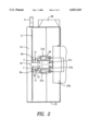
- FIG. 1 is a front view with the housing removed of a numerical controlled router of the invention.
- FIG. 2 is a plan view with the housing removed of a numerical controlled router of FIG. 1.
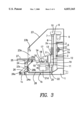
- FIG. 3 is a right side view in partial cross-section of a numerical controlled router of FIG. 1.
- FIG. 4 is a right side view in partial cross-section illustrating motion of the suction table.
- a horizontal beam member 1a is arranged on a support structure 1.
- Horizontal rails 2 are arranged on the side of the horizontal beam member 1a.
- a screw shaft 3 is arranged in a hollow portion of the horizontal beam member 1a between the horizontal rails 2.
- the screw shaft 3 is rotated by a motor 4; sliding bearings and supports 2a and 2b engage the horizontal rails 2 and a screw engaging member 5 is provided on a horizontally movable member 6 between the bearings 2a and 2b.
- Vertical rails 7 are arranged on a front face of the horizontally movable member 6.
- a screw shaft 8 is arranged on the horizontally movable member 6 between the vertical rails 7 and is connected by a connecting member 10 to be rotated by a servomotor 9 arranged at the top portion of the horizontally movable member 6.
- Slidable bearings and supports 11 engage the vertical rails 7 and a screw engaging. member 13 engages the screw shaft 8 to move the vertically movable member 12.
- Rails 15 are mounted on a lower surface of a structure supporting member 14 mounted on the vertically movable member 12.
- a screw shaft 16 arranged in parallel to rails 15 is arranged on the structure supporting member 14 and is rotated by a servomotor 17.
- Bearings and support 18 which engage rails 15 and a screw engaging member 19 are mounted on a head structure 20, and heads 21a, 21b, 21c and 21d are arranged on the head structure 20 so they can be moved toward and away from a process board during the machining of the process board.
- a housing 23 is supported by the horizontal beam member 1a and the beam member 1b of the support structure 1.
- An opening 23a of the housing 23 is formed in front of the head structure 20.
- a suction table supporting member 24 is arranged on the beam member 1b and a suction table 25 is attached to a rotation shaft 25a rotatably mounted on the table supporting member 24.
- An open portion 24a is formed at the center of the table supporting member 24.
- the base member 26a of a table rotating cylinder 26 is rotatably connected to a cylinder supporting member 1c in a portion of the beam member 1b.
- a moving shaft 26b of the table rotating cylinder 26 is connected to the suction table 25.
- An upper support 23b is arranged at the top of the opening 23a of the housing 23 for contact with suction table 25 upon rotation of the suction table 25.
- An under support 23c is attached to the inside of the table supporting member 24.
- the suction table 25 is maintained in a horizontal position by extending the moving shaft 26b of the table rotating cylinder 26. Therefore, after a process board 27 is placed on the suction table 25, the suction table 25 is rotated by retracting the shaft 26b of the table rotating cylinder 26, as shown in FIG. 4.
- the upper end of the suction table 25 abuts against the upper support 23b and the lower end of the suction table 25 abuts against the under support 23c, whereby the suction table 25 is vertically positioned to close the opening 23a of the housing 23.
- the head structure 20 is positioned by moving the horizontally movable member 6 and the vertically movable member 12 by the servomotors 4 and 9. Then the head structure 20 is moved to a predetermined position by the servomotor 17.
- the process board 27 supported by the vacuum on the suction table 25 is machined by the heads 21a to 21d which are horizontally moved by the moving means 22.
- the process board 27 By vertically positioning the process board 27, the wood chips scattered during the machining fall below the suction table 25. Wood chip scattering is stopped by the housing 23. Therefore, it is not necessary to sweep the process board and the suction table. Also, the process board 27 can be easily changed to a new process board by rotating the suction table 25 to a horizontal position.
- the inner portion of the housing 23 can be cleaned at predetermined intervals.
- a factory in which the numerical controlled router of the present invention is used, is kept clean and it is fairly quiet because the noise is absorbed by the housing 23.
- a belt conveyer 28 can be arranged on the support member 1b of the support structure 1 and the end of the belt conveyer 28 can project outside the housing 23; the fallen wood chips and dust are collected outside of the housing 23.
Landscapes
- Engineering & Computer Science (AREA)
- Mechanical Engineering (AREA)
- Milling, Drilling, And Turning Of Wood (AREA)
Applications Claiming Priority (2)
| Application Number | Priority Date | Filing Date | Title |
|---|---|---|---|
| JP9209679A JPH1134009A (ja) | 1997-07-18 | 1997-07-18 | 防塵構造を備えたncルータ |
| JP9-209679 | 1997-07-18 |
Publications (1)
| Publication Number | Publication Date |
|---|---|
| US6033165A true US6033165A (en) | 2000-03-07 |
Family
ID=16576830
Family Applications (1)
| Application Number | Title | Priority Date | Filing Date |
|---|---|---|---|
| US09/022,601 Expired - Fee Related US6033165A (en) | 1997-07-18 | 1998-02-12 | Numerical control router enclosed by a housing |
Country Status (3)
| Country | Link |
|---|---|
| US (1) | US6033165A (ja) |
| EP (1) | EP0893197A2 (ja) |
| JP (1) | JPH1134009A (ja) |
Cited By (1)
| Publication number | Priority date | Publication date | Assignee | Title |
|---|---|---|---|---|
| US20040045146A1 (en) * | 2000-10-11 | 2004-03-11 | Bernd Studemann | Column-type machine tool |
Families Citing this family (4)
| Publication number | Priority date | Publication date | Assignee | Title |
|---|---|---|---|---|
| CN105058125B (zh) * | 2015-08-25 | 2017-04-19 | 东莞市牧豪流体设备科技有限公司 | 一种高度可调节且带筛网的产品夹具 |
| WO2017113044A1 (zh) * | 2015-12-28 | 2017-07-06 | 太仓市微贯机电有限公司 | 一种数控机床移动门 |
| CN106363449B (zh) * | 2016-08-29 | 2018-04-27 | 邢台职业技术学院 | 一种数控机床 |
| CN111716111A (zh) * | 2019-03-20 | 2020-09-29 | 南京大量数控科技有限公司 | 钻孔机的加工平台 |
Citations (8)
| Publication number | Priority date | Publication date | Assignee | Title |
|---|---|---|---|---|
| US4373406A (en) * | 1980-08-01 | 1983-02-15 | Cincinnati Milacron Inc. | Full access pallet shuttle guarding |
| US4842455A (en) * | 1987-10-14 | 1989-06-27 | Chiron-Werke Gmbh & Co. Kg | Protective covering for a machine tool comprising a loading door |
| US4955770A (en) * | 1988-08-31 | 1990-09-11 | Kitamura Machinery Co., Ltd. | Bed for a machine tool |
| US5342156A (en) * | 1992-04-23 | 1994-08-30 | Brother Kogyo Kabushiki Kaisha | Machine tool having partition plates for preventing splash of cutting fluid |
| US5423359A (en) * | 1992-05-16 | 1995-06-13 | Aigner; Georg | Protective hood for wood cutting machines |
| US5658105A (en) * | 1994-10-07 | 1997-08-19 | Brother Kogyo Kabushiki Kaisha | Splash guard for machine tool |
| US5775395A (en) * | 1996-04-10 | 1998-07-07 | Wilkins; David | Vacuum fixture |
| US5836064A (en) * | 1996-03-01 | 1998-11-17 | Chiron-Werke Gmbh & Co. Kg | Machining center |
-
1997
- 1997-07-18 JP JP9209679A patent/JPH1134009A/ja active Pending
- 1997-12-02 EP EP97121178A patent/EP0893197A2/en not_active Withdrawn
-
1998
- 1998-02-12 US US09/022,601 patent/US6033165A/en not_active Expired - Fee Related
Patent Citations (8)
| Publication number | Priority date | Publication date | Assignee | Title |
|---|---|---|---|---|
| US4373406A (en) * | 1980-08-01 | 1983-02-15 | Cincinnati Milacron Inc. | Full access pallet shuttle guarding |
| US4842455A (en) * | 1987-10-14 | 1989-06-27 | Chiron-Werke Gmbh & Co. Kg | Protective covering for a machine tool comprising a loading door |
| US4955770A (en) * | 1988-08-31 | 1990-09-11 | Kitamura Machinery Co., Ltd. | Bed for a machine tool |
| US5342156A (en) * | 1992-04-23 | 1994-08-30 | Brother Kogyo Kabushiki Kaisha | Machine tool having partition plates for preventing splash of cutting fluid |
| US5423359A (en) * | 1992-05-16 | 1995-06-13 | Aigner; Georg | Protective hood for wood cutting machines |
| US5658105A (en) * | 1994-10-07 | 1997-08-19 | Brother Kogyo Kabushiki Kaisha | Splash guard for machine tool |
| US5836064A (en) * | 1996-03-01 | 1998-11-17 | Chiron-Werke Gmbh & Co. Kg | Machining center |
| US5775395A (en) * | 1996-04-10 | 1998-07-07 | Wilkins; David | Vacuum fixture |
Cited By (2)
| Publication number | Priority date | Publication date | Assignee | Title |
|---|---|---|---|---|
| US20040045146A1 (en) * | 2000-10-11 | 2004-03-11 | Bernd Studemann | Column-type machine tool |
| US6880214B2 (en) * | 2000-10-11 | 2005-04-19 | Ds Technologie Werkzeugmaschinenbau Gmbh | Column-type machine tool |
Also Published As
| Publication number | Publication date |
|---|---|
| EP0893197A2 (en) | 1999-01-27 |
| JPH1134009A (ja) | 1999-02-09 |
Similar Documents
| Publication | Publication Date | Title |
|---|---|---|
| EP0650800B1 (en) | A unit for machining workpieces, in particular wood | |
| US6082939A (en) | Machine tool and cover apparatus therefor | |
| KR870002902A (ko) | 다면(多面) 가공장치 | |
| KR20160101190A (ko) | 5축 가공 장치 | |
| EP0500309A2 (en) | Work holding device | |
| US5819395A (en) | Machine tool module with cutting tool and superimposed workpiece-carrying platen | |
| JP2001252837A (ja) | ユニバーサル工作機械 | |
| EP0885689A1 (en) | A numerical control router enclosed by a housing | |
| JP4527270B2 (ja) | 遊技盤の孔あけ加工装置 | |
| JPH04234602A (ja) | 平らな工作物を加工するための工作機械 | |
| KR101111591B1 (ko) | 선반 | |
| EP0893197A2 (en) | A numerical control router enclosed by a housing | |
| JP2684071B2 (ja) | ロータリートランスファーマシン | |
| US5345984A (en) | Pin router apparatus | |
| JP2001038502A (ja) | Nc旋盤 | |
| JP3992468B2 (ja) | 工作機械 | |
| CN120533133B (zh) | 一种多功能走刀车床 | |
| JP2001300827A (ja) | マシニングセンタ | |
| KR200332020Y1 (ko) | 판재 재단기의 조기대 장치 | |
| CN112388403B (zh) | 一种数控磨床开齿机 | |
| CN223186154U (zh) | 一种金属外观件的自动化雕刻设备 | |
| JP7846286B1 (ja) | トラニオンテーブルを有する工作機械 | |
| JP3074477U (ja) | 工作機械 | |
| JPH0461975A (ja) | ワーク洗浄装置 | |
| JP2002001624A (ja) | マシニングセンタにおけるワーク組付テーブル |
Legal Events
| Date | Code | Title | Description |
|---|---|---|---|
| AS | Assignment |
Owner name: HEIAN CORPORATION, JAPAN Free format text: ASSIGNMENT OF ASSIGNORS INTEREST;ASSIGNOR:YAMAUCHI, YOSHIYUKI;REEL/FRAME:008978/0998 Effective date: 19980126 |
|
| REMI | Maintenance fee reminder mailed | ||
| LAPS | Lapse for failure to pay maintenance fees | ||
| FP | Lapsed due to failure to pay maintenance fee |
Effective date: 20040307 |
|
| STCH | Information on status: patent discontinuation |
Free format text: PATENT EXPIRED DUE TO NONPAYMENT OF MAINTENANCE FEES UNDER 37 CFR 1.362 |