US6033214A - Heating apparatus having multiple heating chambers movable between a first position with opposed open sides and a second position with opposed open sides - Google Patents
Heating apparatus having multiple heating chambers movable between a first position with opposed open sides and a second position with opposed open sides Download PDFInfo
- Publication number
- US6033214A US6033214A US09/097,032 US9703298A US6033214A US 6033214 A US6033214 A US 6033214A US 9703298 A US9703298 A US 9703298A US 6033214 A US6033214 A US 6033214A
- Authority
- US
- United States
- Prior art keywords
- heating
- heating chamber
- heating apparatus
- set forth
- stationary support
- Prior art date
- Legal status (The legal status is an assumption and is not a legal conclusion. Google has not performed a legal analysis and makes no representation as to the accuracy of the status listed.)
- Expired - Fee Related
Links
- 238000010438 heat treatment Methods 0.000 title claims abstract description 82
- 238000005096 rolling process Methods 0.000 abstract description 3
- 206010052428 Wound Diseases 0.000 description 1
- 208000027418 Wounds and injury Diseases 0.000 description 1
- 230000001154 acute effect Effects 0.000 description 1
- 238000000034 method Methods 0.000 description 1
- 230000008439 repair process Effects 0.000 description 1
- 230000000717 retained effect Effects 0.000 description 1
Images



Classifications
-
- F—MECHANICAL ENGINEERING; LIGHTING; HEATING; WEAPONS; BLASTING
- F27—FURNACES; KILNS; OVENS; RETORTS
- F27D—DETAILS OR ACCESSORIES OF FURNACES, KILNS, OVENS OR RETORTS, IN SO FAR AS THEY ARE OF KINDS OCCURRING IN MORE THAN ONE KIND OF FURNACE
- F27D99/00—Subject matter not provided for in other groups of this subclass
- F27D99/0001—Heating elements or systems
-
- B—PERFORMING OPERATIONS; TRANSPORTING
- B29—WORKING OF PLASTICS; WORKING OF SUBSTANCES IN A PLASTIC STATE IN GENERAL
- B29B—PREPARATION OR PRETREATMENT OF THE MATERIAL TO BE SHAPED; MAKING GRANULES OR PREFORMS; RECOVERY OF PLASTICS OR OTHER CONSTITUENTS OF WASTE MATERIAL CONTAINING PLASTICS
- B29B13/00—Conditioning or physical treatment of the material to be shaped
- B29B13/02—Conditioning or physical treatment of the material to be shaped by heating
- B29B13/023—Half-products, e.g. films, plates
- B29B13/024—Hollow bodies, e.g. tubes or profiles
-
- B—PERFORMING OPERATIONS; TRANSPORTING
- B29—WORKING OF PLASTICS; WORKING OF SUBSTANCES IN A PLASTIC STATE IN GENERAL
- B29C—SHAPING OR JOINING OF PLASTICS; SHAPING OF MATERIAL IN A PLASTIC STATE, NOT OTHERWISE PROVIDED FOR; AFTER-TREATMENT OF THE SHAPED PRODUCTS, e.g. REPAIRING
- B29C35/00—Heating, cooling or curing, e.g. crosslinking or vulcanising; Apparatus therefor
- B29C35/02—Heating or curing, e.g. crosslinking or vulcanizing during moulding, e.g. in a mould
- B29C35/08—Heating or curing, e.g. crosslinking or vulcanizing during moulding, e.g. in a mould by wave energy or particle radiation
- B29C35/0805—Heating or curing, e.g. crosslinking or vulcanizing during moulding, e.g. in a mould by wave energy or particle radiation using electromagnetic radiation
- B29C2035/0822—Heating or curing, e.g. crosslinking or vulcanizing during moulding, e.g. in a mould by wave energy or particle radiation using electromagnetic radiation using IR radiation
-
- B—PERFORMING OPERATIONS; TRANSPORTING
- B29—WORKING OF PLASTICS; WORKING OF SUBSTANCES IN A PLASTIC STATE IN GENERAL
- B29C—SHAPING OR JOINING OF PLASTICS; SHAPING OF MATERIAL IN A PLASTIC STATE, NOT OTHERWISE PROVIDED FOR; AFTER-TREATMENT OF THE SHAPED PRODUCTS, e.g. REPAIRING
- B29C57/00—Shaping of tube ends, e.g. flanging, belling or closing; Apparatus therefor, e.g. collapsible mandrels
- B29C57/12—Rim rolling
Definitions
- the invention relates to a heating apparatus comprising at least two movably arranged heating boxes which in operating position extensively enclose (closed position) at least one object to be heated and which are movable to an inoperative position in which the object is accessible.
- Such heating apparatuses are used, e.g., in conjunction with lip rolling apparatuses in which blanked and deep-drawn plastic cups are provided with a rolled rim.
- To preheat the plastic cups to a specific prescribed temperature they must pass through a heating section in which they are heated simultaneously on all sides. Consequently, the heating apparatus must be configured such that it encloses the cups.
- the cups also must be accessible if problems should arise in the cup transport through the heating apparatus and the cups must be removed from the heating apparatus manually.
- Multiple-part heating apparatuses allowing to be opened when needed suggest themselves for that purpose. Concerned in the simplest configuration are two heating boxes which enclose the object(s) to be heated and can be folded open for access to their interior.
- the heating boxes are merely moved apart, requiring the operating personnel to reach into the interior of the heating apparatus for removal of any jammed objects. Since the heating apparatus is mostly not turned off for such work, or is still hot, the operator may suffer burn wounds on the hot components.
- a further disadvantage is constituted by the appreciable loss of energy that occurs when opening the heating apparatus. Once the heating apparatus is being closed again after repairs, it takes some time for the desired process temperature to restore.
- the objective underlying the invention is a heating apparatus which avoids the disadvantages of the prior art and guarantees, if needed, nonproblematic access to the objects to be heated, without incurring any heat losses.
- the foregoing objective is met by the provision of a heating apparatus which utilizes at least two heating chambers having open sides which face each other so as to close the chambers.
- the chambers are so arranged relative to each other in a first operating position and in a second inoperative position.
- the first and second positions are 180° apart (eg. front and back).
- the chambers are mounted so as to enable them to be swung in an arc in opposite directions from the first to second positions.
- the design of the heating apparatus is such that the heating boxes are able to swing about, such that in their inoperative position away from the object they are in closed position as well. With the heating apparatus closed also in its inoperative position, no energy losses whatsoever occur during the operator's work. Besides, the heating apparatus is located then a specified distance from the object, so that the operating personnel will in such work make no contact at all with the heating apparatus.
- the heating boxes are preferably of a superjacent arrangement, their open sides facing each other.
- Each heating box is on its two end walls preferably joined, in a fashion allowing swing movement, to a stationary support assembly by way of a parallelogram linkage.
- a parallelogram linkage offers the advantage that the heating boxes retain their position relative to each other when being swung, making it possible to move them, in their inoperative position, to a position corresponding to the working position.
- Both heating boxes move between inoperative and working position along a circular arc, with the top box swinging upward and the bottom box swinging down.
- the heating boxes can thereby transform from one closed position to another closed position.
- the heating boxes retract at the same time from the object being heated.
- the support element features preferably a drive system which hinges to the points of articulation of the parallelogram linkage on the support assembly.
- Arranged in said points of articulation are preferably gears which are engaged by a cogged belt or a respective drive means connecting to a motor.
- FIG. 1 a vertical section of a heating apparatus
- FIG. 2a a plan view of the end face of the heating apparatus shown in FIG. 1, in working position;
- FIG. 2b the heating apparatus relative to FIG. 2a in its inoperative position
- FIG. 3 a side elevation of the heating apparatus with pertaining drive system for swing movement of the heating boxes.
- FIG. 1 illustrates a side elevation of the heating apparatus, which in the depicted embodiment consists of two superjacent heating boxes 1 and 2.
- the heating apparatus is one that precedes a lip rolling apparatus.
- Plastic cups are pushed through the heating apparatus on the guide rods 3a, b and c.
- the configuration of the heating boxes 1 and 2 is such that they extensively enclose, in their operating position, the objects contained on the guide rods.
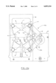
- FIG. 2a shows a plan view of one of the end faces of the heating boxes 1, 2 depicted in FIG. 1.
- the heating boxes 1 and 2 feature in their end walls 5 and 6 an opening 4 through which extend the guide rods 3a, b, c.
- Each parallelogram linkage consists of two equally long knuckle arms 11, 12, which are arranged on a support element 13 in swingable fashion.
- the knuckle arms of the two parallelogram linkages 10a, 10b form in the working position shown in FIG. 2a an acute angle ⁇ with each other.
- the parallelogram linkages 10a, 10b are swung in the direction of the arrow, causing the top heating box 1 to move upward along a circular track while the bottom heating box 2 swings down, as well along a circular track.
- the two heating boxes 1 and 2 move together again, assuming the position shown in FIG. 2b.
- the angle ⁇ has continuously increased in this movement, until reaching the angle ⁇ in the limit position. Due to the parallelogram linkage 10a, b, the alignment of the two heating boxes 1 and 2 relative to each other is retained, so that in their inoperative position shown in FIG. 2b a closed position is reached again.
- the heat contained in the heating chambers 1 and 2 cannot escape while work is under way on the guide rods 3a-c.
- FIG. 3 illustrates a side elevation of the apparatus shown in FIG. 2a, along with the drive system, the heating boxes being covered by the housing 8.
- gears 17a through d are arranged at the hinge points 16a through d of the two parallelogram linkages 10a, b, which are not visible in FIG. 3, and gears 17a through d, connected for rotation to the respective knuckle arms 11 and 12.
- One of the gears, 17b connects by way of the drive chain 15 to the motor 14 (refer also to FIG. 1).
Landscapes
- Engineering & Computer Science (AREA)
- Mechanical Engineering (AREA)
- Physics & Mathematics (AREA)
- Thermal Sciences (AREA)
- General Engineering & Computer Science (AREA)
- Baking, Grill, Roasting (AREA)
- Resistance Heating (AREA)
- Yarns And Mechanical Finishing Of Yarns Or Ropes (AREA)
- Air-Conditioning For Vehicles (AREA)
- Lining Or Joining Of Plastics Or The Like (AREA)
Applications Claiming Priority (2)
| Application Number | Priority Date | Filing Date | Title |
|---|---|---|---|
| DE29711193U DE29711193U1 (de) | 1997-06-27 | 1997-06-27 | Heizvorrichtung |
| DE29711193 | 1997-06-27 |
Publications (1)
| Publication Number | Publication Date |
|---|---|
| US6033214A true US6033214A (en) | 2000-03-07 |
Family
ID=8042220
Family Applications (1)
| Application Number | Title | Priority Date | Filing Date |
|---|---|---|---|
| US09/097,032 Expired - Fee Related US6033214A (en) | 1997-06-27 | 1998-06-12 | Heating apparatus having multiple heating chambers movable between a first position with opposed open sides and a second position with opposed open sides |
Country Status (3)
| Country | Link |
|---|---|
| US (1) | US6033214A (de) |
| EP (1) | EP0887165A3 (de) |
| DE (1) | DE29711193U1 (de) |
Cited By (2)
| Publication number | Priority date | Publication date | Assignee | Title |
|---|---|---|---|---|
| US20050105872A1 (en) * | 2002-02-08 | 2005-05-19 | Fujikura Ltd. | Optical fiber connection tool and optical fiber connection method |
| US8562330B2 (en) | 2009-06-21 | 2013-10-22 | Jere F Irwin | Rim rolling screw having pneumatic cooling |
Family Cites Families (9)
| Publication number | Priority date | Publication date | Assignee | Title |
|---|---|---|---|---|
| US3914102A (en) * | 1974-09-16 | 1975-10-21 | Gaylord William Brown | Apparatus for folding container rims |
| US4439130A (en) * | 1981-11-23 | 1984-03-27 | Cullom Machine Tool & Die, Inc. | Plastic tile corrugator |
| US4556191A (en) * | 1983-04-07 | 1985-12-03 | Mangogna Joseph V | Mold for the manufacture of shoe soles |
| US4911633A (en) * | 1988-08-15 | 1990-03-27 | Comfort Gordon A | Apparatus for plastic tubing manufacture |
| CA2004221C (en) * | 1989-11-29 | 1994-11-08 | Alan Cameron Kirby | Apparatus for heating pipe |
| US5302411A (en) * | 1991-01-22 | 1994-04-12 | Endre Toth | Process for vulcanizing insulated wire |
| GB9107468D0 (en) * | 1991-04-09 | 1991-05-22 | Raychem Ltd | Heating devices |
| DE4113657A1 (de) * | 1991-04-26 | 1992-10-29 | Elastogran Polyurethane Gmbh | Formtraeger zur herstellung von formteilen aus mehrkomponenten-kunststoffen, insbesondere polyurethan |
| CA2121437A1 (en) * | 1993-05-18 | 1994-11-19 | William A. Dempster, Iii | Device for heating pipe surfaces |
-
1997
- 1997-06-27 DE DE29711193U patent/DE29711193U1/de not_active Expired - Lifetime
-
1998
- 1998-06-09 EP EP98110535A patent/EP0887165A3/de not_active Withdrawn
- 1998-06-12 US US09/097,032 patent/US6033214A/en not_active Expired - Fee Related
Cited By (3)
| Publication number | Priority date | Publication date | Assignee | Title |
|---|---|---|---|---|
| US20050105872A1 (en) * | 2002-02-08 | 2005-05-19 | Fujikura Ltd. | Optical fiber connection tool and optical fiber connection method |
| US7258496B2 (en) | 2002-02-08 | 2007-08-21 | Fujikura Ltd. | Optical fiber connection tool and optical fiber connection method |
| US8562330B2 (en) | 2009-06-21 | 2013-10-22 | Jere F Irwin | Rim rolling screw having pneumatic cooling |
Also Published As
| Publication number | Publication date |
|---|---|
| DE29711193U1 (de) | 1997-08-28 |
| EP0887165A2 (de) | 1998-12-30 |
| EP0887165A3 (de) | 1999-06-02 |
Similar Documents
| Publication | Publication Date | Title |
|---|---|---|
| US4995681A (en) | Built-in ironing center | |
| JP4763201B2 (ja) | 側方に摺動可能な複数の壁エレメントを備えたスライド式仕切壁 | |
| RU2005122514A (ru) | Угловой шкаф, в частности кухонный угловой шкаф | |
| EP3351677A1 (de) | Wäschebehandlungsvorrichtung | |
| CA2552839C (en) | Door opening and closing apparatus of oven | |
| SE8307089D0 (sv) | Anordning for manovrering av formhalvor | |
| KR20200077890A (ko) | 다단 링크 힌지 장치 및 이를 포함하는 전자기기 | |
| JP3306383B2 (ja) | 移動自在車収容式熱風消毒保管装置 | |
| US4304448A (en) | Waste bin | |
| CA2041626A1 (en) | Scooping apparatus, vehicle and coupling plate therefor | |
| ATE145529T1 (de) | Drehbeschlag für einen eckschrank | |
| JPS6138700B2 (de) | ||
| EP0471693B1 (de) | Vorrichtung für rotationsformen | |
| CN216603575U (zh) | 消毒机 | |
| CN114099734A (zh) | 消毒机及控制方法 | |
| FI92093C (fi) | Sarana ovea tai vastaavaa rakennetta varten | |
| CN220567597U (zh) | 智能型自动平移冷库门 | |
| CN113040179A (zh) | 一种可全封闭烘烤的自动烘烤设备 | |
| EP0745344B1 (de) | Barbecue zum Kochen von Nahrungsmitteln | |
| US20240124241A1 (en) | Transporting device and heating device | |
| RU2208341C2 (ru) | Шкаф для сушки макаронных изделий | |
| CN113303606B (zh) | 一种多功能衣柜 | |
| JP6054693B2 (ja) | 恒温槽 | |
| JP3136617B2 (ja) | 冷蔵庫 | |
| JP2021132649A (ja) | 乾燥装置 |
Legal Events
| Date | Code | Title | Description |
|---|---|---|---|
| AS | Assignment |
Owner name: BELLAFORM EXTRUSIONSTECHNIK GMBH, GERMANY Free format text: ASSIGNMENT OF ASSIGNORS INTEREST;ASSIGNOR:MERZ, ULRICH;REEL/FRAME:009391/0256 Effective date: 19980724 |
|
| REMI | Maintenance fee reminder mailed | ||
| LAPS | Lapse for failure to pay maintenance fees | ||
| FP | Lapsed due to failure to pay maintenance fee |
Effective date: 20040307 |
|
| STCH | Information on status: patent discontinuation |
Free format text: PATENT EXPIRED DUE TO NONPAYMENT OF MAINTENANCE FEES UNDER 37 CFR 1.362 |