US6033425A - Lifting rib retractor - Google Patents
Lifting rib retractor Download PDFInfo
- Publication number
- US6033425A US6033425A US08/968,949 US96894997A US6033425A US 6033425 A US6033425 A US 6033425A US 96894997 A US96894997 A US 96894997A US 6033425 A US6033425 A US 6033425A
- Authority
- US
- United States
- Prior art keywords
- rack
- section
- blade
- teeth
- retractor
- Prior art date
- Legal status (The legal status is an assumption and is not a legal conclusion. Google has not performed a legal analysis and makes no representation as to the accuracy of the status listed.)
- Expired - Fee Related
Links
Images
Classifications
-
- A—HUMAN NECESSITIES
- A61—MEDICAL OR VETERINARY SCIENCE; HYGIENE
- A61B—DIAGNOSIS; SURGERY; IDENTIFICATION
- A61B17/00—Surgical instruments, devices or methods
- A61B17/02—Surgical instruments, devices or methods for holding wounds open, e.g. retractors; Tractors
- A61B17/0206—Surgical instruments, devices or methods for holding wounds open, e.g. retractors; Tractors with antagonistic arms as supports for retractor elements
-
- A—HUMAN NECESSITIES
- A61—MEDICAL OR VETERINARY SCIENCE; HYGIENE
- A61B—DIAGNOSIS; SURGERY; IDENTIFICATION
- A61B17/00—Surgical instruments, devices or methods
- A61B17/02—Surgical instruments, devices or methods for holding wounds open, e.g. retractors; Tractors
- A61B17/0281—Abdominal wall lifters
Definitions
- the present invention relates to the field of surgery and, more particularly, to an improved rib retractor for accessing the interior of a patient's chest.
- One blade of the rib retractor is raised by an external lifting device relative to the other blade so that the surgeon has an increased field of vision and improved access into the patient's chest cavity.
- Atherosclerosis or coronary artery disease is among the most common and serious health problems confronting the medical profession.
- many different approaches for bypass grafting have been used to surgically correct occluded or stenosed coronary arteries. The approaches all require that the surgeon retract bone structures to access the operative site.
- a sternotomy is probably the most common procedure performed today for providing surgical access to the heart and coronary arteries.
- a sternotomy is highly invasive.
- the patient's skin is incised at the midline overlying the chest and the sternum is cut along its entire length.
- the cut edges of the sternum are spread with metal retractors, exposing a large cavity to allow surgery to be performed on the heart.
- metal retractors use two substantially perpendicular retractor blades that remain generally at the same height in their operative position. This orientation of the blades limits the surgeon's mobility and access to the surgical field, especially for procedures performed deep within the thoracic cavity.
- Bypass grafts are often needed that use homologous tissue, so the surgical procedure also requires grafting the patient's saphenous vein.
- the patient often suffers complications at the graft donor site that are worse and more painful than the sternotomy.
- IMA internal mammary artery
- Coronary bypass procedures thus preferably use a retraction apparatus for exposing the IMA.
- the retraction apparatus should elevate one side of the rib cage to facilitate reaching the IMA.
- a primary problem with thoracoscopic procedures is achieving sufficient area to perform the surgery, particularly since the entry access is limited to the space between ribs. Accordingly, retractors are used to spread apart two adjacent ribs. Since the maximum possible separation between ribs is limited, it is also advantageous to lift one of the spread ribs relative to the adjacent rib.
- One example of creating additional space within the rib cage is a device disclosed in U.S. Pat. No. 5,676,636, entitled “Method for Creating a Mediastinal Working Space.”
- This disclosed device does not spread the ribs, but instead lifts the rib cage to increase the working space for cardiac surgery. Accordingly, this device does not create a "tunnel" that increases the surgeon's field of view, nor does it facilitate grafting the IMA.
- the present invention a rib retractor, satisfies the above-mentioned needs in the art.
- the rib retractor comprises a rack, a first blade fixedly attached to the rack, and a second blade movable along a portion of the rack.
- the rib retractor is adapted to contact two adjacent ribs in the patient through an incision and separate the adjacent ribs apart from each other. Once the ribs are separated, then the surgeon can perform a desired surgical procedure.
- the rack has a first section and a second section, in which the two sections are in a nonlinear orientation relative to each other.
- This design causes one of the ribs to be at a different height than the adjacent rib. That is, the angle that exists between the first and second sections of the rack causes a greater separation than if the rack was linear.
- a linear rack would create lateral separation, whereas the present invention creates both a lateral and oblique separation.
- the rib retractor is adapted to be connected to an external lifting device disposed above the retractor.
- the external lifting device preferably comprises an elongated cable extending between a winch and a hook, which is connected to a portion of the retractor. Rotation of the winch in a lift direction causes the cable to move toward the winch, exerting an upwardly directed force on one blade of the retractor.
- the surgeon incises the patient's skin between two adjacent ribs and the first and second blades are inserted and separated therebetween.
- the surgeon continues to spread the blades until the blades are separated a desired distance to provide access into the thoracic cavity.
- the external lifting device is then connected to the rib retractor and lifts one blade relative to the other blade.
- the nonlinear shape of the rack causes the ribs to be at different heights, providing a greater field of vision and access to the surgical site compared with a conventional retractor having a linear rack that only laterally separates the ribs.
- the blades have spacer portions that position the rack away from the blades in the incision.
- the rack which is the only connection between the separated blades, does not block the surgeon's access into the incision.
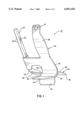
- FIG. 1 is a perspective view of the retractor of the present invention, in which the blades are in the closed position.
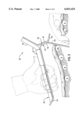
- FIG. 2 is a side view of the retractor being inserted into an intercostal site between two adjacent ribs, in which the body is shown in cross-section.
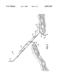
- FIG. 3 is a side view of the retractor, in which the blades are moved to the open position, separating the two adjacent ribs to provide access into the thoracic cavity and in which the body is shown in cross-section.
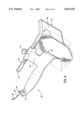
- FIG. 4 is a perspective view of the retractor with the blades open and within an incision.
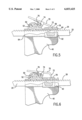
- FIG. 5 is a top plan view of the securing means and the selective disengaging means in partial cross-section, in which the selective disengaging means is in the engaged position.
- FIG. 6 is an alternate view of FIG. 5, in which the selective disengaging means is in the disengaged position.
- the present invention comprises a rib retractor for use in thoracic surgery, specifically heart surgery.
- the rib retractor 10 is adapted to contact two adjacent ribs R in a person through an incision and separate the adjacent ribs R apart from each other. Once the ribs R are separated, then the surgeon can perform a desired surgical procedure, such as coronary artery bypass surgery, mitral valve replacement, and the like.
- the rib retractor 10 of the present invention may also be used as a sternal retractor for maintaining thoracic cavity access via a sternotomy incision or may be used in the abdominal midline, e.g., for maintaining access to the abdomen via a celiotomy incision or the like.
- the rib retractor 10 comprises a rack 20, a first blade 30 fixedly attached to the rack 20, and a second blade 40 movable along a portion of the rack 20.
- the rack 20 has a first section 22 and a second section 24, both of which are preferably linear.
- the first section 22 and the second section 24 form a nonlinear angle ⁇ therebetween.
- the first section 22 is horizontally disposed, the second section 24 is disposed at an angle relative to horizontal.
- the angle ⁇ that the first section 22 and the second section 24 form is preferably between 15° and 90°, more preferably between 30° and 60°, and most preferably between 45° and 50°.
- the rack 20 preferably has a plurality of teeth 26 disposed along at least a portion of the second section 24 of the rack 20.
- Both the first blade 30 has a contact side and an opposed external side.
- the first blade 30 also has two opposed side edges 36.
- the second blade 40 has a contact side 42, an external side 44, and two opposed side edges 46.
- the blades 30, 40 preferably have a squared shape in cross section so that the blade comprises three sections. When the second section 24 of the rack 20 is oriented upwardly as in FIGS. 1, 2, and 4, the upward-most sections of the first and second blades 30, 40 is the top end 38, 48 of the respective blades 30, 40.
- Other blade shapes are also contemplated, such as blades that are substantially "V" shaped in cross section.
- a portion of the first blade 30 is preferably fixedly attached to the first section 22 of the rack 20. As best shown in FIG. 1, the top end 38 of the first blade 30 adjacent one of its edges is welded to the first section 22 of the rack 20.
- the present invention also includes a means for movably attaching one edge 46 of the second blade 40 to the second section 24 of the rack 20. With the attaching means, the second blade 40 is movable relative to the first blade 30 along a portion of the length of the second section 24 of the rack 20.
- the attaching means allows the first blade 30 and second blade 40 to move between a closed position and open position.
- a portion of the external sides 34, 44 of first and second blades 30, 40 contact each other.
- the open position shown in FIGS. 3 and 4, the external sides 34, 44 are spaced apart from each other.
- the preferred attaching means comprises a pinion 50 having a plurality of teeth 52 therein, a means for positioning the pinion 50 relative to the second blade 40, and a turning member 54 (shown in FIG. 4).
- the teeth 52 of the pinion 50 matingly engage the teeth 26 of the rack 20 and the positioning means positions the pinion 50 so that its teeth 52 rotatably and movably engage the teeth 26 of the rack 20.
- the positioning member in the shown embodiment is an aligning member 60, which is discussed below.
- the turning member 54 has a bottom end fixedly attached to a portion of the pinion 50 so that rotation of the turning member 54 causes the pinion 50 to rotate. Rotation of the pinion 50 correspondingly causes the second blade 40 to move along at least a portion of the length of the second section 24 of the rack 20.
- the present invention also comprises a means for securing the second blade 40 at selected points along the length of the second section 24 of the rack 20 and a means for selectively disengaging the securing means.
- the securing means comprises the aligning member 60 and a pawl arm 70 having a pawl tooth 72.
- the aligning member 60 has an exterior surface 62 and defines a bore 64 therethrough.
- the bore 64 is of a size to slidably receive the rack 20 therein.
- the second blade 40 is fixedly attached, such as by welding, to a portion of the exterior surface 62 of the aligning member 60.
- Another portion of the exterior surface 62 has a slot 66 therethrough communicating with the bore 64 of the aligning member 60.
- the slot 66 is disposed over and in registry with the teeth 26 in the rack 20.
- the securing means also preferably comprises a means for pivotally mounting the pawl arm 70 to a portion of the exterior surface 62 of the aligning member 60 so that the pawl tooth 72 is movable to communicate selectively with the teeth 26 of the rack 20 through the slot 66.
- the pivotal mounting means is a pin 74 attached to the attachment member about which the pawl arm 70 rotates, although other pivotal mounting means can be used, such as a hinge (not shown), swivel (not shown) and the like. It is also contemplated that the pawl tooth 72 can communicate with the teeth 26 in the rack 20 independent of using the slot 66, e.g., the pawl tooth 72 extending off one end of the aligning member 60 to communicate with the teeth 26.
- the securing means preferably further comprises a means for biasing the pawl tooth 72 of the pawl arm 70 toward the teeth 26 of the rack 20 so that the pawl tooth 72 is capable of selectively engaging the teeth 26 of the rack 20.
- the biasing means is a spring clip 76, or torsional spring, having one end fixedly attached to a portion of the exterior surface 62 of the aligning member 60 and another end fixedly attached to a portion of the pawl arm 70.
- the spring clip 76 biases the pawl tooth 72 toward the teeth 26 of the rack 20, as shown in FIG. 5.
- FIG. 6 shows the spring clip 76 biasing the pawl tooth 72 downwardly, although the pawl tooth 72 is not engaging the teeth 26 of the rack 20.
- Other biasing means include a coiled spring (not shown), torque tube (not shown), and the like.
- the selective disengaging means comprises a pawl detachment member 78 slidably mounted over at least a portion of the exterior surface 62 of the aligning member 60.
- the pawl detachment member 78 is movable between a disengaged position and an engaged position.
- FIG. 6 shows the disengaged position, in which the pawl detachment member 78 is disposed over at least a portion of the slot 66 in the aligning member 60 intermediate the pawl tooth 72 and the teeth 26 of the rack 20 to prevent communication therewith.
- the pawl detachment member 78 which is in the engaged position, is disposed so that the pawl tooth 72 can communicate with the teeth 26 of the rack 20 through the slot 66 of the aligning member 60.
- the aligning member 60 and attached second blade 40 are freely movable along the second section 24 of the rack 20 since the pawl tooth 72 does not contact the teeth 26 of the rack 20. Conversely, when in the engaged position, the pawl tooth 72 interfacing with teeth 26 in the rack 20 prevents this free movement.
- the pawl arm 70 is preferably oriented parallel to the length of the second section 24 of the rack 20 and the pawl tooth 72 is disposed intermediate the opposed first blade 30 and the pivotal mounting means.
- the second blade 40 based on the position of the pivotal mounting means and the biasing means, is movable away from the first blade 30 and is prevented from moving toward the first blade 30 while the pawl tooth 72 is engaged with the teeth 26 of the rack 20.
- both the first blade 30 and the second blade 40 are movable along the first section 22 and the second section 24 of the rack 20, respectively. That is, in this alternative embodiment, both the first blade 30 and the second blade 40 have attaching means movably connecting the blades 30, 40 to the rack 20, instead of one blade being fixedly attached to the rack 20.
- the retractor 10 of the present invention is preferably used with an external lifting device disposed above the retractor 10.
- the external lifting device preferably comprises an elongated cable 80, having a first end (not shown) and a second end 82, and a winch (not shown).
- the winch has an axis of rotation and a barrel about which a portion of the cable 80 is disposed.
- the first end of the cable 80 is detachably secured to a portion of the barrel.
- a hook 84 is preferably used with the external lifting device and attached to the second end 82 of the cable 80.
- the external lifting device also includes a means for rotating the winch about its axis of rotation, such as a crank (not shown).
- a means for rotating the winch about its axis of rotation such as a crank (not shown).
- One embodiment of the external lifting device is manufactured by Rultract Incorporated of Cleveland, Ohio, namely, the Rultract IMA Retractor.
- the connecting means comprises an opening 47 through a portion of the second blade 40 of a size to complementarily receive a portion of the hook 84 therein.
- Rotation of the crank in a lift direction causes the cable 80 to rotate about the barrel and the hook 84 to move toward the barrel, exerting an upwardly directed force on the second blade 40.
- Rotation in a lower direction causes the hook 84 to move in the opposite direction.
- the surgeon incises the patient's skin between two adjacent ribs B.
- the surgeon will access the heart via the fourth intercostal space located between the third and fourth ribs, but this may differ based on the individual patient's anatomy.
- a portion of the second blade 40 is pushed into the incision and then the first blade 30 is also inserted.
- the contact side 32 of the first blade 30 is adapted to engage a first selected rib FR of a patient and the contact side 42 of the second blade 40 is adapted to engage a second selected rib SR of the patient.
- the first selected rib FR and the second selected rib SR are located adjacent to each other.
- the first and second blades 30, 40 are moved to an open position.
- the turning member 54 is twisted, causing the pinion 50 to rotate and move the second blade 40 along the second section 24 of the rack 20 away from the stationary first blade 30.
- the surgeon continues to spread the blades 30, 40 until the blades 30, 40 are separated a desired distance from each other.
- the surgeon can then lift the second blade 40 relative to the first blade 30, which is shown in FIGS. 3 and 4.
- the hook 84 of the external lifting device creates the upwardly-directed force. That is, the surgeon turns the crank of the winch of the external lifting device to pull the hook 84 toward the winch, thus lifting the second blade 40 of the retractor 10 with respect to the first blade 30 because of the leverage applied to the retractor 10.
- the first blade 30 of the retractor 10 remains at substantially the same height and functions as a fulcrum to cause the ribs R to be spread obliquely to the rib cage.
- the first blade 30 acts as a fulcrum because of its connection to the first section 22 and the angle ⁇ between the first and second sections 22, 24. Accordingly, the rib SR in contact with the second blade 40 is raised relative to the rib FR in contact with the first blade 30, which is shown best in FIG. 3. It is also contemplated to connect the blades to a straight rack at angles to achieve the same result.
- the retractor 10 of the present invention increases the field of vision relative to a conventional retractor by providing a "tunnel" to view the surgical site. That is, the field of vision is greater than in FIG, 2, in which the first selected rib FR and the second selected rib SR are at substantially the same height.
- the perspective view shows a different view of the field of vision that the surgeon enjoys with the present invention.
- the blades 30, 40 are laterally elongated, or have spacer portions 39, 49, that position the rack 20 away from the incision.
- the rack 20 does not block the surgeon's access through the incision.
- the contact portion of the blade is approximately two (2) inches wide and the spacer portion 39, 49 is approximately one (1) inch wide, e.g., the spacer portion offsets the rack 20 over one inch from where the blades 30, 40 contact the selected ribs FR, SR.
- the rack 20 is the only connection between the first blade 30 and the second blade 40, as opposed to having a wide frame interconnecting the blades 30, 40.
- the rack 20 is only three tenths (0.03) of an inch wide in the preferred embodiment, which provides minimal potential blockage of the surgical site.
Landscapes
- Health & Medical Sciences (AREA)
- Life Sciences & Earth Sciences (AREA)
- Surgery (AREA)
- Heart & Thoracic Surgery (AREA)
- Engineering & Computer Science (AREA)
- Biomedical Technology (AREA)
- Nuclear Medicine, Radiotherapy & Molecular Imaging (AREA)
- Medical Informatics (AREA)
- Molecular Biology (AREA)
- Animal Behavior & Ethology (AREA)
- General Health & Medical Sciences (AREA)
- Public Health (AREA)
- Veterinary Medicine (AREA)
- Surgical Instruments (AREA)
Priority Applications (6)
| Application Number | Priority Date | Filing Date | Title |
|---|---|---|---|
| US08/968,949 US6033425A (en) | 1997-11-12 | 1997-11-12 | Lifting rib retractor |
| PCT/US1998/024136 WO1999023935A1 (fr) | 1997-11-12 | 1998-11-12 | Ecarteur de cotes avec moyen de soulevement |
| AU14023/99A AU1402399A (en) | 1997-11-12 | 1998-11-12 | Lifting rib retractor |
| CA002309825A CA2309825C (fr) | 1997-11-12 | 1998-11-12 | Ecarteur de cotes avec moyen de soulevement |
| EP98957869A EP1030588A4 (fr) | 1997-11-12 | 1998-11-12 | Ecarteur de cotes avec moyen de soulevement |
| US09/495,466 US6159231A (en) | 1997-11-12 | 2000-02-01 | Lifting rib retractor |
Applications Claiming Priority (1)
| Application Number | Priority Date | Filing Date | Title |
|---|---|---|---|
| US08/968,949 US6033425A (en) | 1997-11-12 | 1997-11-12 | Lifting rib retractor |
Related Child Applications (1)
| Application Number | Title | Priority Date | Filing Date |
|---|---|---|---|
| US09/495,466 Continuation US6159231A (en) | 1997-11-12 | 2000-02-01 | Lifting rib retractor |
Publications (1)
| Publication Number | Publication Date |
|---|---|
| US6033425A true US6033425A (en) | 2000-03-07 |
Family
ID=25514978
Family Applications (2)
| Application Number | Title | Priority Date | Filing Date |
|---|---|---|---|
| US08/968,949 Expired - Fee Related US6033425A (en) | 1997-11-12 | 1997-11-12 | Lifting rib retractor |
| US09/495,466 Expired - Lifetime US6159231A (en) | 1997-11-12 | 2000-02-01 | Lifting rib retractor |
Family Applications After (1)
| Application Number | Title | Priority Date | Filing Date |
|---|---|---|---|
| US09/495,466 Expired - Lifetime US6159231A (en) | 1997-11-12 | 2000-02-01 | Lifting rib retractor |
Country Status (5)
| Country | Link |
|---|---|
| US (2) | US6033425A (fr) |
| EP (1) | EP1030588A4 (fr) |
| AU (1) | AU1402399A (fr) |
| CA (1) | CA2309825C (fr) |
| WO (1) | WO1999023935A1 (fr) |
Cited By (25)
| Publication number | Priority date | Publication date | Assignee | Title |
|---|---|---|---|---|
| US20040092797A1 (en) * | 2002-06-24 | 2004-05-13 | James Yi | Lifting tool for surgical retractors |
| US20040186354A1 (en) * | 2003-03-20 | 2004-09-23 | Lidonnici Leslie | Methods and devices for minimizing the loss of blood through a severed sternum during cardiac and/or thoracic surgery |
| US20040236184A1 (en) * | 1998-05-01 | 2004-11-25 | Benetti Federico J. | Xyphoid access for surgical procedures |
| US20050148824A1 (en) * | 2003-12-30 | 2005-07-07 | Morejohn Dwight P. | Transabdominal surgery system |
| US20070191924A1 (en) * | 2004-03-21 | 2007-08-16 | Leon Rudakov | Method for treating aneurysms |
| US20080215054A1 (en) * | 2007-01-26 | 2008-09-04 | Genesee Biomedical, Inc. | Devices and Methods for Minimizing the Hemorrhage from and Minimizing Infection of a Divided Sternum During Cardiac Surgery |
| US20080262494A1 (en) * | 2007-04-17 | 2008-10-23 | Warsaw Orthopedic, Inc. | Spinal tool |
| US20090275804A1 (en) * | 2008-04-30 | 2009-11-05 | Rudolf Bertagnoli | Hinged Retractor With Sheath |
| US20110201892A1 (en) * | 2010-02-12 | 2011-08-18 | Fiona Middlemiss Haig | Expandable thoracic access port |
| US20110201896A1 (en) * | 2010-02-12 | 2011-08-18 | O'prey Cormac | Expandable surgical access port |
| US20110201894A1 (en) * | 2010-02-12 | 2011-08-18 | O'prey Cormac | Expandable thoracic access port |
| US8540628B2 (en) | 2010-02-12 | 2013-09-24 | Covidien Lp | Expandable thoracic access port |
| US8597180B2 (en) | 2010-08-12 | 2013-12-03 | Covidien Lp | Expandable thoracic access port |
| US8864658B2 (en) | 2010-08-12 | 2014-10-21 | Covidien Lp | Expandable surgical access port |
| US8961408B2 (en) | 2010-08-12 | 2015-02-24 | Covidien Lp | Expandable surgical access port |
| US8961409B2 (en) | 2011-12-07 | 2015-02-24 | Covidien Lp | Thoracic access assembly |
| US9039610B2 (en) | 2011-05-19 | 2015-05-26 | Covidien Lp | Thoracic access port |
| US9119665B2 (en) | 2011-03-21 | 2015-09-01 | Covidien Lp | Thoracic access port including foldable anchor |
| US9247955B2 (en) | 2010-08-12 | 2016-02-02 | Covidien Lp | Thoracic access port |
| US9572561B2 (en) | 2012-03-12 | 2017-02-21 | Emory University | Sternal retractor |
| US10987128B2 (en) | 2017-03-22 | 2021-04-27 | Covidien Lp | Cannula assembly |
| US11039824B1 (en) * | 2018-06-07 | 2021-06-22 | Thomas P. Sterry | Surgical retractor device |
| US11141191B2 (en) | 2020-01-15 | 2021-10-12 | Covidien Lp | Surgical access assembly |
| CN115252019A (zh) * | 2022-08-31 | 2022-11-01 | 王联群 | 用于微创冠脉搭桥手术的牵开器 |
| US12251130B2 (en) | 2021-05-03 | 2025-03-18 | Covidien Lp | Surgical access device having a balloon and methods for manufacturing the same |
Families Citing this family (24)
| Publication number | Priority date | Publication date | Assignee | Title |
|---|---|---|---|---|
| US5888247A (en) | 1995-04-10 | 1999-03-30 | Cardiothoracic Systems, Inc | Method for coronary artery bypass |
| CA2198036C (fr) * | 1996-02-20 | 2000-12-05 | Charles S. Taylor | Plate-forme d'acces pour la dissection de l'artere thoracique interne |
| US6283912B1 (en) | 1999-05-04 | 2001-09-04 | Cardiothoracic Systems, Inc. | Surgical retractor platform blade apparatus |
| US20040049206A1 (en) * | 2002-09-06 | 2004-03-11 | Rassman William R. | Scalp tensioner |
| US20040127773A1 (en) * | 2002-12-31 | 2004-07-01 | Ethicon, Inc. | Curved rack retractor |
| DE10325393B3 (de) | 2003-05-28 | 2005-01-05 | Karl Storz Gmbh & Co. Kg | Retraktor |
| US8083664B2 (en) | 2005-05-25 | 2011-12-27 | Maquet Cardiovascular Llc | Surgical stabilizers and methods for use in reduced-access surgical sites |
| GB0800835D0 (en) | 2008-01-17 | 2008-02-27 | Cardioprec Ltd | Retractor |
| US8388631B2 (en) * | 2009-01-23 | 2013-03-05 | Restoration Robotics, Inc. | Skin tensioner for hair transplantation |
| US8465498B2 (en) * | 2010-01-15 | 2013-06-18 | Restoration Robotics, Inc. | Tensioning device and method for hair transplantation |
| AU2011268433A1 (en) | 2010-06-14 | 2013-01-10 | Maquet Cardiovascular Llc | Surgical instruments, systems and methods of use |
| GB201015746D0 (en) | 2010-09-21 | 2010-10-27 | Cardioprec Ltd | Optical switch |
| US9131935B2 (en) * | 2010-10-01 | 2015-09-15 | K2M, Inc. | Retractor |
| US9510913B2 (en) | 2012-09-12 | 2016-12-06 | Restoration Robotics, Inc. | Skin tensioning devices and methods of their use |
| US9392965B2 (en) | 2013-03-14 | 2016-07-19 | Restoration Robotics, Inc. | Method and apparatus for determining a change in tension of a body surface |
| US9408691B2 (en) | 2013-03-14 | 2016-08-09 | Restoration Robotics, Inc. | Locator device for medical procedures on the body surface and method of its use |
| US9999414B2 (en) | 2014-01-24 | 2018-06-19 | Contour Surgical, Inc. | Retraction devices and methods of its use and manufacture |
| US10016189B2 (en) * | 2014-12-15 | 2018-07-10 | Lsi Solutions, Inc. | Surgical rib retractor and methods thereof |
| US10433960B1 (en) | 2015-05-07 | 2019-10-08 | Cardioprecision Limited | Method and system for transcatheter intervention |
| WO2017218717A1 (fr) | 2016-06-14 | 2017-12-21 | Lsi Solutions, Inc. | Rétracteur chirurgical de côte |
| US10603025B2 (en) | 2016-06-14 | 2020-03-31 | Lsi Solutions, Inc. | Surgical rib retractor |
| EP3998957A4 (fr) | 2019-08-14 | 2023-08-09 | LSI Solutions, Inc. | Rétracteur chirurgical de côte |
| US11944286B2 (en) | 2020-01-24 | 2024-04-02 | Lsi Solutions, Inc. | Surgical rib retractor |
| US11826036B2 (en) | 2021-12-03 | 2023-11-28 | Lsi Solutions, Inc. | Epigastric retractor |
Citations (25)
| Publication number | Priority date | Publication date | Assignee | Title |
|---|---|---|---|---|
| FR473451A (fr) * | 1914-06-15 | 1915-01-13 | Pierre Antoine Gentile | Écarteur à écartement parallèle perfectionné |
| US4156424A (en) * | 1978-05-01 | 1979-05-29 | Burgin Kermit H | Locking adjustable speculum |
| US4259036A (en) * | 1979-07-13 | 1981-03-31 | Pullman Incorporated | Hopper car door locking arrangement |
| US4461284A (en) * | 1982-09-30 | 1984-07-24 | Fackler Martin L | Surgical retaining device |
| US4622955A (en) * | 1985-09-05 | 1986-11-18 | Mehdi Fakhrai | Surgical retractor for dissection of internal mammary artery |
| US4627421A (en) * | 1984-08-03 | 1986-12-09 | Symbas Panagiotis N | Sternal retractor |
| US4726356A (en) * | 1985-11-12 | 1988-02-23 | Kapp Surgical Instrument, Inc. | Cardiovascular and thoracic retractor |
| US4747394A (en) * | 1986-10-08 | 1988-05-31 | Watanabe Orthopedic Systems, Inc. | Spinal retractor |
| US4829985A (en) * | 1986-05-28 | 1989-05-16 | Delacroix-Chevalier | Sternal retractor |
| US4852552A (en) * | 1987-09-03 | 1989-08-01 | Pilling Co. | Sternal retractor |
| EP0356410A1 (fr) * | 1988-08-16 | 1990-02-28 | Mogens Bugge | Dispositif destiné à être utilisé pour l'ouverture de la poitrine en chirurgie |
| US4989587A (en) * | 1989-04-26 | 1991-02-05 | Farley Daniel K | Sternal retractor |
| US5052373A (en) * | 1988-07-29 | 1991-10-01 | Michelson Gary K | Spinal retractor |
| US5067477A (en) * | 1989-08-01 | 1991-11-26 | Codman & Shurtleff, Inc. | Low wear bearing for a surgical retractor |
| US5088472A (en) * | 1990-04-04 | 1992-02-18 | Mehdi Fakhrai | Retractor |
| US5167223A (en) * | 1989-09-08 | 1992-12-01 | Tibor Koros | Heart valve retractor and sternum spreader surgical instrument |
| US5365921A (en) * | 1993-01-22 | 1994-11-22 | Bookwalter John R | Flip-up sternal retractor |
| US5616117A (en) * | 1995-08-03 | 1997-04-01 | Ohio Medical Instrument Company, Inc. | Self locking surgical retractor |
| EP0792620A2 (fr) * | 1996-02-20 | 1997-09-03 | Cardiothoracic Systems, Inc. | Plates-formes d'accès pour la dissection de l'artère mamillaire interne |
| US5676636A (en) * | 1994-07-22 | 1997-10-14 | Origin Medsystems, Inc. | Method for creating a mediastinal working space |
| WO1998027869A1 (fr) * | 1996-12-23 | 1998-07-02 | University Of Massachusetts | Appareil et procede de chirurgie avec effraction minimale |
| US5782746A (en) * | 1996-02-15 | 1998-07-21 | Wright; John T. M. | Local cardiac immobilization surgical device |
| US5788630A (en) * | 1996-09-25 | 1998-08-04 | Genzyme Corporation | Rib retractor |
| CA2216893A1 (fr) * | 1997-08-27 | 1999-02-27 | Raymond Cartier | Retracteur de sternum pour effectuer un pontage sur un coeur battant |
| US5894843A (en) * | 1996-02-20 | 1999-04-20 | Cardiothoracic Systems, Inc. | Surgical method for stabilizing the beating heart during coronary artery bypass graft surgery |
Family Cites Families (3)
| Publication number | Priority date | Publication date | Assignee | Title |
|---|---|---|---|---|
| FR690530A (fr) * | 1930-02-25 | 1930-09-23 | écarteur chirurgical | |
| US2450194A (en) * | 1946-07-22 | 1948-09-28 | Glaser Mark Albert | Adjustable retractor |
| DE815521C (de) * | 1949-04-01 | 1951-10-01 | Hans Dr Med Killian | Hilfseinrichtung fuer Operationen |
-
1997
- 1997-11-12 US US08/968,949 patent/US6033425A/en not_active Expired - Fee Related
-
1998
- 1998-11-12 EP EP98957869A patent/EP1030588A4/fr not_active Withdrawn
- 1998-11-12 WO PCT/US1998/024136 patent/WO1999023935A1/fr not_active Ceased
- 1998-11-12 AU AU14023/99A patent/AU1402399A/en not_active Abandoned
- 1998-11-12 CA CA002309825A patent/CA2309825C/fr not_active Expired - Fee Related
-
2000
- 2000-02-01 US US09/495,466 patent/US6159231A/en not_active Expired - Lifetime
Patent Citations (26)
| Publication number | Priority date | Publication date | Assignee | Title |
|---|---|---|---|---|
| FR473451A (fr) * | 1914-06-15 | 1915-01-13 | Pierre Antoine Gentile | Écarteur à écartement parallèle perfectionné |
| US4156424A (en) * | 1978-05-01 | 1979-05-29 | Burgin Kermit H | Locking adjustable speculum |
| US4259036A (en) * | 1979-07-13 | 1981-03-31 | Pullman Incorporated | Hopper car door locking arrangement |
| US4461284A (en) * | 1982-09-30 | 1984-07-24 | Fackler Martin L | Surgical retaining device |
| US4627421A (en) * | 1984-08-03 | 1986-12-09 | Symbas Panagiotis N | Sternal retractor |
| US4622955A (en) * | 1985-09-05 | 1986-11-18 | Mehdi Fakhrai | Surgical retractor for dissection of internal mammary artery |
| US4726356A (en) * | 1985-11-12 | 1988-02-23 | Kapp Surgical Instrument, Inc. | Cardiovascular and thoracic retractor |
| US4829985A (en) * | 1986-05-28 | 1989-05-16 | Delacroix-Chevalier | Sternal retractor |
| US4747394A (en) * | 1986-10-08 | 1988-05-31 | Watanabe Orthopedic Systems, Inc. | Spinal retractor |
| US4852552A (en) * | 1987-09-03 | 1989-08-01 | Pilling Co. | Sternal retractor |
| US5052373A (en) * | 1988-07-29 | 1991-10-01 | Michelson Gary K | Spinal retractor |
| US5025779A (en) * | 1988-08-16 | 1991-06-25 | Mogens Bugge | Device intended to be used for opening the chest during surgery |
| EP0356410A1 (fr) * | 1988-08-16 | 1990-02-28 | Mogens Bugge | Dispositif destiné à être utilisé pour l'ouverture de la poitrine en chirurgie |
| US4989587A (en) * | 1989-04-26 | 1991-02-05 | Farley Daniel K | Sternal retractor |
| US5067477A (en) * | 1989-08-01 | 1991-11-26 | Codman & Shurtleff, Inc. | Low wear bearing for a surgical retractor |
| US5167223A (en) * | 1989-09-08 | 1992-12-01 | Tibor Koros | Heart valve retractor and sternum spreader surgical instrument |
| US5088472A (en) * | 1990-04-04 | 1992-02-18 | Mehdi Fakhrai | Retractor |
| US5365921A (en) * | 1993-01-22 | 1994-11-22 | Bookwalter John R | Flip-up sternal retractor |
| US5676636A (en) * | 1994-07-22 | 1997-10-14 | Origin Medsystems, Inc. | Method for creating a mediastinal working space |
| US5616117A (en) * | 1995-08-03 | 1997-04-01 | Ohio Medical Instrument Company, Inc. | Self locking surgical retractor |
| US5782746A (en) * | 1996-02-15 | 1998-07-21 | Wright; John T. M. | Local cardiac immobilization surgical device |
| EP0792620A2 (fr) * | 1996-02-20 | 1997-09-03 | Cardiothoracic Systems, Inc. | Plates-formes d'accès pour la dissection de l'artère mamillaire interne |
| US5894843A (en) * | 1996-02-20 | 1999-04-20 | Cardiothoracic Systems, Inc. | Surgical method for stabilizing the beating heart during coronary artery bypass graft surgery |
| US5788630A (en) * | 1996-09-25 | 1998-08-04 | Genzyme Corporation | Rib retractor |
| WO1998027869A1 (fr) * | 1996-12-23 | 1998-07-02 | University Of Massachusetts | Appareil et procede de chirurgie avec effraction minimale |
| CA2216893A1 (fr) * | 1997-08-27 | 1999-02-27 | Raymond Cartier | Retracteur de sternum pour effectuer un pontage sur un coeur battant |
Non-Patent Citations (36)
| Title |
|---|
| "A New Concept in Sternal Retraction: Applications for Internal Mammary Artery Dissection and Valve Replacement Surgery," Aurelio Chaux, MD, and Carlos Blanche, MD, The Annals of Thoracic Surgery, 473-74, Oct. 1986. |
| "A New Internal Mammary Artery Retractor," M. Bugge, Thoracic Cardiovascular Surgeon 38, 316-17 (1990). |
| "A New Retractor to Aid in Coronary Artery Surgery," A.J. DelRossi, MD, G.M. Lemole, MD, The Annals of Thoracic Surgery, vol. 36, No. 1, 101-02, Jul. 1983. |
| "A Versatile Retractor for Use in Harvesting the Internal Mammary Artery and Performing Standard Cardiac Operations," Steven J. Phillips, MD, and Marge Core, RN, The Journal of Thoracic Surgery, 1989; 97: 633-35. |
| "Cardiac Retractor for Coronary Bypass Operations," John A. Rousou, MD, et al., The Annals of Thoracic Surgery, 1991, 52: 877-78. |
| "Internal Mammary Artery Dissection: A Three Dimensional Sternal Retractor," D. Roux, MD, et al., Journal Cardiovasic Surgery, 30, 996-97, 1989. |
| "Less Invasive Coronary Surgery: Cosensus From the Oxford Meeting," Stephen Westaby, FRCS, and Federico J. Benetti, MD, The Annals of Thoracic Surgery 1996; 62:924-31. |
| "Mini-Sternotomy for Coronary Artery Bypass Grafting," Kit V. Arom, MD, PhD, et al., The Annals of Thoracic Surgery 1996; 61:1271-2. |
| "New Helper Instrument in Cardiac Surgery," D. Roux, MD, et al., The Annals of Thoracic Surgery, 1989, 48: 595-6. |
| "Off-Bypass Coronary Bypass Grafting Via Mimithoracotomy Using Mechanical Epicardial Stabilization," Jochen Cremer, MD, et al., The Annals of Thoracic Surgery 1997; 63:s79-83. |
| "Technique of Dissecting the Internal Mammary After Using the Moussalli Bar," R.I. Hasan, et al. European Journal of Cardiothoracic Surgery,4:571-572, 1990. |
| "Technique of Internal Mammary--Coronary Artery Anastomosis," The Journal of Cardiovascular Surgery, 78: 455-79, 1979. |
| A New Concept in Sternal Retraction: Applications for Internal Mammary Artery Dissection and Valve Replacement Surgery, Aurelio Chaux, MD, and Carlos Blanche, MD, The Annals of Thoracic Surgery , 473 74, Oct. 1986. * |
| A New Device for Exposing the Circumflex Coronary Artery, Akio Matsuura, MD, et al., The Annals of Thoracic Surgery 1995; 59:1249 50. * |
| A New Device for Exposing the Circumflex Coronary Artery, Akio Matsuura, MD, et al., The Annals of Thoracic Surgery 1995; 59:1249-50. |
| A New Internal Mammary Artery Retractor, M. Bugge, Thoracic Cardiovascular Surgeon 38, 316 17 (1990). * |
| A New Retractor to Aid in Coronary Artery Surgery, A.J. DelRossi, MD, G.M. Lemole, MD, The Annals of Thoracic Surgery , vol. 36, No. 1, 101 02, Jul. 1983. * |
| A Versatile Retractor for Use in Harvesting the Internal Mammary Artery and Performing Standard Cardiac Operations, Steven J. Phillips, MD, and Marge Core, RN, The Journal of Thoracic Surgery, 1989; 97: 633 35. * |
| Boonsstra et al., Local Immobilizatio of the Left Anterior Descending Artery for Minimally Invasive Coronary Bypass Grafting, Ann Thorac Surg, 63:567 569 (1997). * |
| Boonsstra et al., Local Immobilizatio of the Left Anterior Descending Artery for Minimally Invasive Coronary Bypass Grafting, Ann Thorac Surg, 63:567-569 (1997). |
| Cardiac Retractor for Coronary Bypass Operations, John A. Rousou, MD, et al., The Annals of Thoracic Surgery , 1991, 52: 877 78. * |
| Internal Mammary Artery Dissection: A Three Dimensional Sternal Retractor, D. Roux, MD, et al., Journal Cardiovasic Surgery , 30, 996 97, 1989. * |
| Less Invasive Coronary Surgery: Cosensus From the Oxford Meeting, Stephen Westaby, FRCS, and Federico J. Benetti, MD, The Annals of Thoracic Surgery 1996; 62:924 31. * |
| Limited Access Myocardial Revascularization, Denton A. Cooley, MD, Texas Heart Institute Journal, vol. 23, No. 2, 1996. * |
| Mini Sternotomy for Coronary Artery Bypass Grafting, Kit V. Arom, MD, PhD, et al., The Annals of Thoracic Surgery 1996; 61:1271 2. * |
| New Helper Instrument in Cardiac Surgery, D. Roux, MD, et al., The Annals of Thoracic Surgery , 1989, 48: 595 6. * |
| Off Bypass Coronary Bypass Grafting Via Mimithoracotomy Using Mechanical Epicardial Stabilization, Jochen Cremer, MD, et al., The Annals of Thoracic Surgery 1997; 63:s79 83. * |
| Promotional Literature (catalog) Aesculap Instruments Corp. (Feb. 1993). * |
| Promotional Literature, Miltex (date unknown). * |
| Promotional Literature, Pilling Surgical Instruments, A Rusch Inter. Co., (1993). * |
| Promotional Literature, T. Koros Surgical Instruments Corp. (1994). * |
| Rultract Incorporated brochure, Surgical Retractor Systems, (1995). * |
| Technique of Dissecting the Internal Mammary After Using the Moussalli Bar, R.I. Hasan, et al. European Journal of Cardiothoracic Surgery ,4:571 572, 1990. * |
| Technique of Internal Mammary Coronary Artery Anastomosis, The Journal of Cardiovascular Surgery , 78: 455 79, 1979. * |
| USSC, Thora LIFT booklet, Rib Lifter Retractor For Minimally Ivasive Cardiac Surgery and photograph of device (May 1997). * |
| USSC, Thora-LIFT booklet, "Rib Lifter Retractor For Minimally Ivasive Cardiac Surgery" and photograph of device (May 1997). |
Cited By (37)
| Publication number | Priority date | Publication date | Assignee | Title |
|---|---|---|---|---|
| US20040236184A1 (en) * | 1998-05-01 | 2004-11-25 | Benetti Federico J. | Xyphoid access for surgical procedures |
| US20040092797A1 (en) * | 2002-06-24 | 2004-05-13 | James Yi | Lifting tool for surgical retractors |
| US7186215B2 (en) | 2002-06-24 | 2007-03-06 | James Yi | Lifting tool for surgical retractors |
| US20040186354A1 (en) * | 2003-03-20 | 2004-09-23 | Lidonnici Leslie | Methods and devices for minimizing the loss of blood through a severed sternum during cardiac and/or thoracic surgery |
| US7011628B2 (en) | 2003-03-20 | 2006-03-14 | Lidonnici Leslie | Methods and devices for minimizing the loss of blood through a severed sternum during cardiac and/or thoracic surgery |
| US20050148824A1 (en) * | 2003-12-30 | 2005-07-07 | Morejohn Dwight P. | Transabdominal surgery system |
| US20070191924A1 (en) * | 2004-03-21 | 2007-08-16 | Leon Rudakov | Method for treating aneurysms |
| US20080215054A1 (en) * | 2007-01-26 | 2008-09-04 | Genesee Biomedical, Inc. | Devices and Methods for Minimizing the Hemorrhage from and Minimizing Infection of a Divided Sternum During Cardiac Surgery |
| US20080262494A1 (en) * | 2007-04-17 | 2008-10-23 | Warsaw Orthopedic, Inc. | Spinal tool |
| US20090275804A1 (en) * | 2008-04-30 | 2009-11-05 | Rudolf Bertagnoli | Hinged Retractor With Sheath |
| US20110201892A1 (en) * | 2010-02-12 | 2011-08-18 | Fiona Middlemiss Haig | Expandable thoracic access port |
| US20110201896A1 (en) * | 2010-02-12 | 2011-08-18 | O'prey Cormac | Expandable surgical access port |
| US20110201894A1 (en) * | 2010-02-12 | 2011-08-18 | O'prey Cormac | Expandable thoracic access port |
| US8540628B2 (en) | 2010-02-12 | 2013-09-24 | Covidien Lp | Expandable thoracic access port |
| US8574155B2 (en) | 2010-02-12 | 2013-11-05 | Covidien Lp | Expandable surgical access port |
| US8579810B2 (en) | 2010-02-12 | 2013-11-12 | Covidien Lp | Expandable thoracic access port |
| US9402613B2 (en) | 2010-02-12 | 2016-08-02 | Covidien Lp | Expandable thoracic access port |
| US8777849B2 (en) | 2010-02-12 | 2014-07-15 | Covidien Lp | Expandable thoracic access port |
| US8864658B2 (en) | 2010-08-12 | 2014-10-21 | Covidien Lp | Expandable surgical access port |
| US9168031B2 (en) | 2010-08-12 | 2015-10-27 | Covidien Lp | Expandable thoracic access port |
| US9247955B2 (en) | 2010-08-12 | 2016-02-02 | Covidien Lp | Thoracic access port |
| US8597180B2 (en) | 2010-08-12 | 2013-12-03 | Covidien Lp | Expandable thoracic access port |
| US8961408B2 (en) | 2010-08-12 | 2015-02-24 | Covidien Lp | Expandable surgical access port |
| US9597114B2 (en) | 2010-08-12 | 2017-03-21 | Covidien Lp | Expandable surgical access port |
| US9119665B2 (en) | 2011-03-21 | 2015-09-01 | Covidien Lp | Thoracic access port including foldable anchor |
| US9549722B2 (en) | 2011-03-21 | 2017-01-24 | Covidien Lp | Thoracic access port including foldable anchor |
| US10420541B2 (en) | 2011-05-19 | 2019-09-24 | Covidien Lp | Thoracic access port |
| US9039610B2 (en) | 2011-05-19 | 2015-05-26 | Covidien Lp | Thoracic access port |
| US8961409B2 (en) | 2011-12-07 | 2015-02-24 | Covidien Lp | Thoracic access assembly |
| US9629657B2 (en) | 2011-12-07 | 2017-04-25 | Covidien Lp | Thoracic access assembly |
| US9572561B2 (en) | 2012-03-12 | 2017-02-21 | Emory University | Sternal retractor |
| US10987128B2 (en) | 2017-03-22 | 2021-04-27 | Covidien Lp | Cannula assembly |
| US11864792B2 (en) | 2017-03-22 | 2024-01-09 | Covidien Lp | Cannula assembly |
| US11039824B1 (en) * | 2018-06-07 | 2021-06-22 | Thomas P. Sterry | Surgical retractor device |
| US11141191B2 (en) | 2020-01-15 | 2021-10-12 | Covidien Lp | Surgical access assembly |
| US12251130B2 (en) | 2021-05-03 | 2025-03-18 | Covidien Lp | Surgical access device having a balloon and methods for manufacturing the same |
| CN115252019A (zh) * | 2022-08-31 | 2022-11-01 | 王联群 | 用于微创冠脉搭桥手术的牵开器 |
Also Published As
| Publication number | Publication date |
|---|---|
| EP1030588A1 (fr) | 2000-08-30 |
| CA2309825A1 (fr) | 1999-05-20 |
| AU1402399A (en) | 1999-05-31 |
| CA2309825C (fr) | 2007-01-09 |
| EP1030588A4 (fr) | 2009-04-08 |
| US6159231A (en) | 2000-12-12 |
| WO1999023935A1 (fr) | 1999-05-20 |
Similar Documents
| Publication | Publication Date | Title |
|---|---|---|
| US6033425A (en) | Lifting rib retractor | |
| US5976171A (en) | Access platform for internal mammary dissection | |
| US5730757A (en) | Access platform for internal mammary dissection | |
| US7014609B2 (en) | Articulation member for use in a surgical apparatus | |
| EP1009289B1 (fr) | Stabilisation du coeur en fonctionnement au cours d'une operation chirurgicale de pontage coronarien | |
| US5944736A (en) | Access platform for internal mammary dissection | |
| US6348036B1 (en) | Surgical retractor and tissue stabilization device | |
| US6695868B2 (en) | Sled assembly for use with a surgical retractor and medical instrument and methods related thereto | |
| US6500116B1 (en) | Surgical retractor having improved blades | |
| US6599240B2 (en) | Segmented arm assembly for use with a surgical retractor and instruments and methods related thereto | |
| US5788630A (en) | Rib retractor | |
| US6730022B2 (en) | Surgical retractor and tissue stabilization device having an adjustable sled member | |
| US5931778A (en) | Rib retractor | |
| WO1999015081A1 (fr) | Retracteur et souleveur de cotes | |
| WO2000042937A1 (fr) | Bras de stabilisation courbe destine a etre utilise avec un ecarteur chirurgical et dispositif de stabilisation des tissus |
Legal Events
| Date | Code | Title | Description |
|---|---|---|---|
| AS | Assignment |
Owner name: GENZYME CORPORATION, MASSACHUSETTS Free format text: ASSIGNMENT OF ASSIGNORS INTEREST;ASSIGNORS:LOONEY, CHRISTOPHER SEAN;EVANS, DOUGLAS G.;REEL/FRAME:008925/0395 Effective date: 19971112 |
|
| CC | Certificate of correction | ||
| AS | Assignment |
Owner name: TELEFLEX-CT DEVICES INCORPORATED, PENNSYLVANIA Free format text: ASSIGNMENT OF ASSIGNORS INTEREST;ASSIGNOR:GENZYME CORPORATION;REEL/FRAME:014363/0776 Effective date: 20030630 Owner name: TELEFLEX-CT DEVICES INCORPORATED,PENNSYLVANIA Free format text: ASSIGNMENT OF ASSIGNORS INTEREST;ASSIGNOR:GENZYME CORPORATION;REEL/FRAME:014363/0776 Effective date: 20030630 |
|
| REMI | Maintenance fee reminder mailed | ||
| FPAY | Fee payment |
Year of fee payment: 4 |
|
| SULP | Surcharge for late payment | ||
| AS | Assignment |
Owner name: TECHNOLOGY HOLDING COMPANY II, DELAWARE Free format text: ASSIGNMENT OF ASSIGNORS INTEREST;ASSIGNOR:TELEFLEX-CT DEVICES INCORPORATED;REEL/FRAME:016059/0332 Effective date: 20031217 |
|
| FPAY | Fee payment |
Year of fee payment: 8 |
|
| REMI | Maintenance fee reminder mailed | ||
| FEPP | Fee payment procedure |
Free format text: PAYOR NUMBER ASSIGNED (ORIGINAL EVENT CODE: ASPN); ENTITY STATUS OF PATENT OWNER: LARGE ENTITY Free format text: PAYER NUMBER DE-ASSIGNED (ORIGINAL EVENT CODE: RMPN); ENTITY STATUS OF PATENT OWNER: LARGE ENTITY |
|
| REMI | Maintenance fee reminder mailed | ||
| LAPS | Lapse for failure to pay maintenance fees | ||
| STCH | Information on status: patent discontinuation |
Free format text: PATENT EXPIRED DUE TO NONPAYMENT OF MAINTENANCE FEES UNDER 37 CFR 1.362 |
|
| FP | Lapsed due to failure to pay maintenance fee |
Effective date: 20120307 |