US6057532A - Infra-red radiation sources - Google Patents
Infra-red radiation sources Download PDFInfo
- Publication number
- US6057532A US6057532A US08/553,309 US55330996A US6057532A US 6057532 A US6057532 A US 6057532A US 55330996 A US55330996 A US 55330996A US 6057532 A US6057532 A US 6057532A
- Authority
- US
- United States
- Prior art keywords
- infra
- red radiation
- conductive element
- electrically conductive
- radiation source
- Prior art date
- Legal status (The legal status is an assumption and is not a legal conclusion. Google has not performed a legal analysis and makes no representation as to the accuracy of the status listed.)
- Expired - Lifetime
Links
Images


Classifications
-
- H—ELECTRICITY
- H05—ELECTRIC TECHNIQUES NOT OTHERWISE PROVIDED FOR
- H05B—ELECTRIC HEATING; ELECTRIC LIGHT SOURCES NOT OTHERWISE PROVIDED FOR; CIRCUIT ARRANGEMENTS FOR ELECTRIC LIGHT SOURCES, IN GENERAL
- H05B3/00—Ohmic-resistance heating
- H05B3/10—Heating elements characterised by the composition or nature of the materials or by the arrangement of the conductor
- H05B3/12—Heating elements characterised by the composition or nature of the materials or by the arrangement of the conductor characterised by the composition or nature of the conductive material
- H05B3/14—Heating elements characterised by the composition or nature of the materials or by the arrangement of the conductor characterised by the composition or nature of the conductive material the material being non-metallic
- H05B3/145—Carbon only, e.g. carbon black, graphite
-
- H—ELECTRICITY
- H05—ELECTRIC TECHNIQUES NOT OTHERWISE PROVIDED FOR
- H05B—ELECTRIC HEATING; ELECTRIC LIGHT SOURCES NOT OTHERWISE PROVIDED FOR; CIRCUIT ARRANGEMENTS FOR ELECTRIC LIGHT SOURCES, IN GENERAL
- H05B3/00—Ohmic-resistance heating
- H05B3/0033—Heating devices using lamps
- H05B3/0071—Heating devices using lamps for domestic applications
- H05B3/0076—Heating devices using lamps for domestic applications for cooking, e.g. in ovens
-
- H—ELECTRICITY
- H05—ELECTRIC TECHNIQUES NOT OTHERWISE PROVIDED FOR
- H05B—ELECTRIC HEATING; ELECTRIC LIGHT SOURCES NOT OTHERWISE PROVIDED FOR; CIRCUIT ARRANGEMENTS FOR ELECTRIC LIGHT SOURCES, IN GENERAL
- H05B3/00—Ohmic-resistance heating
- H05B3/0033—Heating devices using lamps
- H05B3/009—Heating devices using lamps heating devices not specially adapted for a particular application
-
- H—ELECTRICITY
- H05—ELECTRIC TECHNIQUES NOT OTHERWISE PROVIDED FOR
- H05B—ELECTRIC HEATING; ELECTRIC LIGHT SOURCES NOT OTHERWISE PROVIDED FOR; CIRCUIT ARRANGEMENTS FOR ELECTRIC LIGHT SOURCES, IN GENERAL
- H05B3/00—Ohmic-resistance heating
- H05B3/02—Details
- H05B3/06—Heater elements structurally combined with coupling elements or holders
- H05B3/08—Heater elements structurally combined with coupling elements or holders having electric connections specially adapted for high temperatures
Definitions
- the present invention relates to infra-red radiation sources and in particular to those sources comprising an electrically conductive element formed of a plurality of carbon fibres.
- Infra-red radiation sources are used as heat sources in commercial process ovens, domestic cooker hot plates and ovens, and radiant energy electrical heaters.
- the or each carbon fibre element is supported at opposite ends between two members which are adapted so as to facilitate the connection of the element across an electrical power supply.
- these supporting members have been formed of metals such as tungsten, molybdenum, nickel or steel.
- one of the problems associated with carbon fibre infra-red radiation sources is the tendency for the element to become sufficiently degraded within the region of the metal supporting members as to result in the failure of the radiation source after only a few tens of hours of operation. This degradation comes about as a result of either migration of carbon atoms from the conductive element into the metal of the or each supporting member or as a result of a reaction between the carbon and the metal to form the apropriate metal carbide. In either event carbon atoms are removed from the element resulting in its eventual collapse. As the carbon atoms are removed there is a tendency for the temperature of the element to increase which in turn only serves to exacerbate the mechanisms by which the carbon is lost.
- an infra-red radiation source comprising an electrically conductive element formed of a plurality of carbon fibres and connection means for connecting the electrically conductive element across an electrical power supply, the connection means including at least one support member formed of carbon and secured to one end of the electrically conductive element.
- an infra-red radiation source comprising an electrically conductive element formed of a plurality of carbon fibres and connection means for connecting the electrically conductive element across an electrical power supply, said connection means including at least one support member secured to one end of the electrically conductive element and formed of or coated with a metal through which carbon does not diffuse.
- an infra-red radiation source comprising a housing formed of a material transparent to infra-red radiation, an electrically conductive element located within the housing and formed of a plurality of carbon fibres, connection means for connecting the electrically conductive element across an electrical power supply and restraining means for limiting unwanted movement of the conductive element with respect to the housing.
- a method of making an infra-red radiation source comprising the steps of forming an electrically conductive element from a plurality of carbon-fibres, securing to at least one end of the electrically conductive element a support member formed of carbon and connecting to the support member means for connecting the electrically conductive element across an electrical power supply.
- a method of making an infra-red radiation source comprising the steps of forming an electrically conductive element from a plurality of carbon-fibres, securing to at least one end of the electrically conductive element a support member formed of a material through which carbon does not diffuse, and connecting to the support member means for connecting the electrically conductive element across an electrical power supply.
- a method of making an infra-red radiation source comprising the steps of forming an electrically conductive element of a plurality of carbon fibres, disposing the electrically conductive element within a housing formed of a material transparent to infra-red radiation, providing the electrically conductive element with means to limit unwanted movement of the electrically conductive element with respect to the housing and securing to the electrically conductive element means for connecting the electrically conductive element across an electrical power supply.
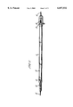
- FIG. 1 is a schematic perspective view of an infra-red radiation source
- FIG. 2 is a cross-sectional side view of a support member for use in conjunction with one embodiment of the present invention
- FIG. 3 is a plan view of the support member of FIG. 2;
- FIG. 4 is a cross-sectional side view of a support member for use in conjunction with another embodiment of the present invention.
- FIG. 5 is a plan view of the support member of FIG. 4;
- FIG. 6 is a cross-sectional side view of a support member for use in conjunction with another embodiment of the present invention.
- FIG. 7 is a plan view of the support member of FIG. 6;
- FIG. 8 is a cross-sectional side view of a first arrangement whereby the support member of FIG. 6 is attached to an electrical conductor;
- FIG. 9 is a schematic perspective view of the arrangement of FIG. 8;
- FIG. 10 is a cross-sectional side view of a second arrangement whereby the support member of FIG. 6 is attached to an electrical conductor;
- FIG. 11 is a schematic perspective view of the arrangement of FIG. 10;
- FIG. 12 is a cross-sectional side view of a third arrangement whereby the support member of FIG. 6 is attached to an electrical conductor;
- FIG. 13 is a shcematic perspective view of the arrangement of FIG. 12;
- FIG. 14 is a cross-sectional side view of a fourth arrangement whereby the support member of FIG. 6 is attached to an electrical conductor;
- FIG. 15 is an exploded perspective view of the arrangement of FIG. 14;
- FIG. 16 is a cross-sectional side view of a fifth arrangement whereby the support member of FIG. 6 is attached to an electrical conductor;
- FIG. 17 is an exploded perspective view of the arrangement of FIG. 16;
- FIG. 18 is a cross-sectional side view of a sixth arrangement whereby the support member of FIG. 6 is attached to an electrical conductor;
- FIG. 19 is a plan view of the arrangement of FIG. 18;
- FIG. 20 is a cross-sectional side view of a first arrangement whereby the electrically conductive element may be located with respect to a surrounding tube;
- FIG. 21 is a cross-sectional end view of the arrangement of FIG. 20;
- FIG. 22 is a cross-sectional side view of a second arrangement whereby the electrically conductive element may be located with respect to a surrounding tube;
- FIG. 23 is a cross-sectional end view of the arrangement of FIG. 22;
- FIG. 24 is a cross-sectional side view of a third arrangement whereby the electrically conductive element may be located with respect to a surrounding tube;
- FIG. 25 is a cross-sectional end view of the arrangement of FIG. 24.
- the infra-red radiation source may be seen to comprise a tube 1 of material which is transparent to infra-red radiation, such as for example a ceramic material such as quarzglas or fused silica.
- the tube 1 contains an electrically conductive element 2 in the form of a flat or coiled strip formed of carbon fibres which are coated with and bonded by the carbon residue of a carbonised resin.
- At each end of the strip 2 there is provided a respective one of two connectors 3 which are both mechanically and electrically connected to the strip 2.
- Each connector 3 is connected to a respective electrical conductor 4 which is in turn connected to a respective electrical feed through lead 5 which passes through an otherwise closed end of the tube 1.
- the electrical feed through leads 5 are adapted so as to be connectable across a suitable electrical power supply such that in use the strip 2 may be caused to emit infra-red radiation.
- the or each connector 3 is formed of a metal, such as copper, through which carbon does not diffuse or of a metal coated with another metal through which carbon does not diffuse.
- the metal connectors 3 may be either alloyed or coated with a material that will both wet the surface of the carbon fibres of the strip 2 and provide a good electrical contact between the strip and the or each connector 3.
- One way in which this might be achieved for a copper connector is to alloy the copper with 1% chromium.
- a metal that is capable of wetting both copper and the carbon fibres of the electrically conductive element is gold which may thus be used at an interface between the two materials. Irrespective of the metal coating that is used the coating may be applied to the ends of the electrically conductive element 2 either by an electroplating process or by the application of a metal based paint which is subsequently heated to drive off the solvent and/or organic carrier to leave the metal deposit.
- the or each connector 3 comprises a pair of carbon blocks 6,7 disposed on either side of the electrically conductive element 2 and which are secured together so as to retain the element therebetween.
- the blocks 6,7 and the strip 2 are both heated whilst being pressed together then additional bonding may occur as a result of the melting and subsequent carbonising of the carbon-based resin used to coat the carbon fibres in either event the increased thickness of carbon at the or each connector 3 when compared with the central region of the strip 2 provides the two fold advantage of reducing the heat generated within the vicinity of and conducted to the electrical conductors 4 whilst at the same time providing additional strength for mechanical connection.
- this mechanical connection is provided by means of a nut and bolt or rivet 8 which passes through a through-bore 9 provided in each of the carbon blocks 6,7 and which extends in a direction substantially perpendicular to the plane of the carbon fibre strip 2.
- the nut and bolt or rivet 8 serves to secure the connector 3 to its respective electrical conductor 4 which, in the example shown, is formed of molybdenum.
- Molybdenum is preferred for the formation of both the electrical conductors 4 and the feed through leads 5 for a number of reasons. Firstly, molybdenum is a non-ferrous, refractory metal that does not stress relieve at temperatures below 1000° C. while secondly molybdenum is less able than, say, nickel or stainless steel, to catalyse those reactions that are damaging to the carbon of the electrically conductive element.
- the or each connector 3 is formed of a plurality of carbon fibre layers 10 which are laid one on top of the other and then carbonised to form an end portion of the elctrically conductive element 2 of increased thickness.
- the or each connector 3 may be secured to its respective electrical conductor 4 by means of a nut and bolt or rivet 8 although it is to be noted that as in the embodiment illustrated the electrical conductor 4 may comprise two mutually spaced parallel strips each of which is attached to an opposing surface of the connector 3.
- the or each electrical conductor 4 is preferably formed of molybdenum.
- the or each connector 3 may comprise a quantity of graphite paper which is disposed by wrapping or otherwise so as to lie adjacent opposing surfaces of the carbon fibre strip 2 and form a graphite pad 11.
- the graphite paper is preferably a crushable tape typically 1 mm in thickness and which is made primarily of graphite (99% carbon).
- One such tape is sold by Le Carbonne under their product reference Papyex H995 SR.
- each graphite pad 11 and graphite paper is cut so as to have a width substantially equal to that of the carbon fibre strip 2 whilst at the same time having a length of approximately 20 mm.
- the cut lengths of graphite paper are then adhered to opposing surfaces of the carbon fibre strip at each end by means of a double sided adhesive tape.
- One such tape suitable for this purpose comprises a 0.1 mm thick polypropelene tape coated on both sides with a synthetic rubber adhesive.
- the polypropelene tape partially decomposes and the carbon-based resin used to coat the carbon fibres of the conductive element melts to form a strong uniform bond with the graphite paper on cooling.
- the resulting graphite pads act as a buffer to prevent the loss of carbon from the electrically conductive element in the vicinity of the or each electrical conductor 4 by means of diffusion or arcing.
- the graphite pad may be connected to its respective electrical conductor 4 in a variety of ways.
- FIGS. 8 and 9 One such method of attachment is shown in FIGS. 8 and 9 to comprise a molybdenum strip 112 which is arranged so as to overlie the graphite pad 11 and extend in a direction substantially parallel to the carbon fibre strip 2.
- Two molybdenum straps 13 and 14 are then arranged so as to overlie and extend in a direction transverse to the molybdenum strip 12, the molybdenum straps 13,14 being of sufficient length so as to be capable of being folded first down the sides and then underneath the graphite pad 11.
- the molybdenum straps 13 and 14 serve to retain the molybdenum strip in contact with the graphite pad however, for added security an end portion 15 of the molybdenum strip 12 adjacent the electrically conductive element 2 may be folded back on itself to overlie and engage one or both of the molybdenum straps 13,14. Finally, the molybdenum strip 12 and molybdenum straps 13 and 14 are crushed into the graphite pad 11 to provide good electrical contact and a reliable mechanical connection between the pad and the electrical conductor 4.
- the electrical conductor 4 is formed of a length of molybdenum wire which is wrapped around the graphite pad 11 in a spiral. As in the previous arrangement the molybdenum wire is then crushed into the graphite pad to ensure a reliable electrical contact and a good mechanical connection.
- the graphite pad 11 is provided with a pair of mutually spaced through bores 16 and 17 each of which has a through-axis that extends in a direction substantially perpendicular to the plane of the carbon fibre strip 2.
- the electrical connector 4 comprises a rectangular molybdenum plate 18 which is provided along each of its shorter sides with a pair of mutually spaced, parallel cuts that extend longitudinally of the plate. These two pairs of cuts serve to define two fingers 19 and 20 that may be folded out of the plane of the molybdenum plate 18 so as to project substantially perpendicularly therefrom. In this configuration which is shown in FIG.
- the graphite pad 11 may be received by the molybdenum plate 18 in such a way that each of the fingers 19 and 20 is received by and projects through a respective one of the two through-bores 16 and 17. Having been received in this way the two fingers 19 and 20 may be folded so that that portion of the fingers which project from the through-bores 16 and 17 is caused to overlie the surface of the graphite pad 11 which is opposed to that which lies adjacent the molybdenum plate 18.
- FIG. 12 One such folded arrangement is shown in FIG. 12.
- the molybdenum plate 18 and the now folded fingers 19 and 20 may be compressed into the graphite pad 11 to ensure reliable electrical contact and a secure mechanical connection.
- the graphite pad 11 may again be provided with a through-bore 21 having a through-axis which extends substantially perpendicularly to the plane of the carbon fibre strip 2.
- the electrical conductor 4 may comprise a first substantially planar member 22 having a projecting boss 23 disposed toward one end of the member and a second stepped member 24 having a depending boss 25 located on an under surface of a stepped portion 26.
- the graphite pad 11 is first positioned on the substantially planar member 22 in such a way that the projecting boss 23 is received within the through-bore 21. Thereafter the stepped member 24 is positioned on top of the planar member 22 in such a way that the stepped portion 26 overlies the graphite pad 11 and the depending boss 25 is received within the through-bore 21. Once in this position the stepped member 24 may be secured to the planar member 22 by one or more spot welds at locations where the two members are in mutual abutment. As shown in FIG. 14 these locations may include a region within the through-bore 21 as well as within a region to the side of the graphite pad 11 remote from the carbon fibre strip 2.
- first and second members 22 and 24 may be compressed into the graphite pad 11 so as to ensure a reliable electrical contact and a secure mechanical connection.
- the graphite pad 11 may be provide with one or more pairs of mutually spaced, parallel through-bores 27 each having a through-axis that extends substantially perpendicularly to the plane of the carbon fibre strip 2.
- the electrical conductor 4 may again comprise a substantially planar molybdenum strip 28 this time having a corresponding number of pairs of mutually spaced through-holes 29.
- the graphite pad 11 is first positioned on the molybdenum strip 28 in such a way that each pair of through-bores 27 is aligned with a corresponding pair of through-holes 29. Thereafter one or more molybdenum staples 30 each comprising a cross piece 31 and a pair of depending legs 32 and 33 are inserted into the graphite pad 11 in such a way that the cross piece 31 overlies a surface of the graphite pad remote from the molybdenum strip 28 while the two depending legs 32 and 33 extend through a respective one of each pair of through-bores 27 and project from the corresponding through holes 29.
- portion of the depending legs 32 and 33 that project from the through-holes 29 may be folded so as to lie adjacent the molybdenum strip 28.
- the molybdenum strip and staple 28 and 30 may be compressed into the graphite pad 11 so as to ensure a reliable electrical contact and a secure mechanical connection.
- the graphite pad 11 is again provided with a through-bore 34 having a through-axis that extends substantially perpendicular to the plane of the carbon fibre strip 2.
- the electrical conductor 4 may comprise a substantially C-shaped molybdenum strip which is so sized as to be capable of receiving the graphite pad 11 between the projecting limbs 36 of the C-shape.
- Each of these limbs 36 is provided with an opening 37 which, when the graphite pad 11 is received within the C-shaped strip 35, is an alignment with the through-bore 34.
- the graphite pad 11 may be secured to the C-shaped strip 35 simply by means of a molybdenum rivet 38.
- the carbon fibres of the strip 2 may be treated either before or after the attachment of the connectors 3 to provide a surface coating of vitreous carbon that bonds the fibres together.
- vitreous is used to refer to the properties of a material whose atomic constituents are bound, though not so as to form any regular crystalline structure.
- the carbon fibres of the strip 2 can be considered to be carbon/carbon composite filaments formed from carbon fibres which have been coated with a layer of carbon-based resin and then pyrolysed in an inert atmosphere at an elevated temperature so that the resin is carbonised in a similar manner to that described in the article by Newling and Walker, published in Plastics and Polymers Conference Supplement Number 5, Paper No. 37, pages 142 to 153 (Publishers: Plastics Institute, London, February 1971), which is the proceedings of a Conference entitled "Carbon Fibres, their Composites and application”.
- the temperature of pyrolysation is typically below 2600° C. The reason for this is that the coating graphitises at a higher temperature reducing the emissivity of the strip 2 as well as changing the mechanical properties of the coating.
- the strip 2 forms the element of the source and has an emissivity close to unity for all infra-red wavelengths between 1 and 10 microns. This is important to ensure rapid loss of heat on de-energising the electrical power.
- the strip 2 is preferably formed to a uniform thin section having a thickness of between 30 and 400 microns at a central region intermediate the connectors 3 in order to satisfy durability and response time criteria.
- a strip thickness of 200 microns on application of a constant current that would eventually raise the strip temperature to 1000° C. when radiating to a surrounding at ambient temperature, the strip 2 would be heated to a temperature where it is radiating 70% of its final output in three seconds.
- the strip 2 For a strip at 1000° C. radiating to a surrounding at ambient temperature, on removing the energising current, the strip 2 would cool sufficiently rapidly so as to radiate less than 30% of its initial output in two seconds.
- the resistivity of a strip 2 formed from carbon fibres coated in this way changes by less than 20% on heating from ambient temperature to 1000° C.
- an infra-red radiation source is assembled by inserting the electrically conductive element and the respective connectors 3 into a quarzglas tube or housing 1.
- the electrically conductive element 2 may be held in position with respect to the tube simply by means of the relative positioning of the connectors 3 whilst a small spring may be provided as part of the electrical conductor 4 to compensate for an expansion of up to 1 mm in the dimensions of element during high temperature operation.
- the quarzglas tube 1 may be provided at intervals along its length with a plurality of pairs of diametrically opposed pinches 39.
- One such pinch is shown in FIG. 21 to comprise an arcuate recess 40 provided in the wall of the tube which is defined by two radially inwardly projecting indentations 41 and 42.
- the carbon fibre strip 2 is mounted with respect to the tube 1 in such a way that the strip and the pinches 39 are substantially co-planar.
- the carbon fibre strip may be received within the arcuate recess 40 of each of the pairs of diametrically opposed pinches 39.
- the electrically conductive element may be orientated with respect to the tube 1 and constrained from unwanted lateral or rotational movement whilst at the same time being allowed to expand and contract in a longitudinal direction.
- the quarzglas tube 1 is again provided at intervals along its length with a plurality of pairs of diametrically opposed pinches 39.
- the pinches 39 serve to retain a carbon fibre or graphite paper yoke 43 and it is this yoke that serves to prevent excessive lateral or rotational movement of the electrically conductive element whilst at the same time allowing for expansion of the element in a longitudinal direction.
- the yoke 43 may be formed from graphite paper or resin-impregnated carbon fibre bonded together at a pressure of approximately 6 Kg and at a temperature of between 300 and 400° C. If the yoke 43, is formed of graphite paper, then the yoke may be further supported by a tantalum shim which may not only provide the yoke with an increased rigidity but may also act as an oxygen getter.
- the yoke 43 has been illustrated as being received within a number of pairs of diametrically opposed pinches 39 disposed at intervals along the length of the tube 1 this need not necessarily be the case. Indeed, the quarzglas tube need not be provided with any type of formation on its internal surface with which to engage the yoke and instead the yoke may simply act as a spacer to locate the electrically conductive element 2 with respect to the walls of the tube 1.
- a plurality of carbon fibre spacers 44 are woven through the electrically conductive element 2 at intervals along its length in such a way that the spacers extend in a direction substantially co-planar with but tranverse to the electrically conductive element.
- Each of the carbon fibre spacers 44 is preferably of sufficient length such that its opposite ends are capable of engaging opposing regions on the walls of the quarzglas tube 1. In this way the spacers 44 may simply act to locate the electrically conductive element 2 with respect to the tube 1.
- the tube 1 may be provided at intervals along its length with a plurality of pairs of diametrically opposed pinches 39 capable of receiving the opposite ends of the spacers 44.
- the electrically conductive element 2 is formed of a plurality of carbon fibres which extend longitudinally of the element means that the element is capable of a slight longitudinal movement with respect to the spacers 44 which can be utilised to allow for contraction and expansion of the element.
- the tube 1 is sealed and can either be filled with a chemically inert gas of low thermal conductivity, such as argon, at sub-atmospheric pressure, or evacuated.
- a chemically inert gas of low thermal conductivity such as argon, at sub-atmospheric pressure, or evacuated.
- the filling pressure of the gas is chosen so that the infra-red transparent tube 1 is not unduly stressed throughout the operating temperature range of the source while the specific gas that is used is chosen to prevent deterioration of the surface of the carbon fibres of the strip 2 by oxidation and to minimise heat transfer from the strip 2 to the tube 1.
- any method of protecting the strip 2 from oxidation may be used.
- One such method might be the application of a protective coating capable of withstanding the high temperature of operation of the source.
- One such coating might comprise silicon carbide (SiC).
- the surface of the strip 2 may be doped with boron.
Landscapes
- Resistance Heating (AREA)
Applications Claiming Priority (3)
| Application Number | Priority Date | Filing Date | Title |
|---|---|---|---|
| GB9310499A GB2278722A (en) | 1993-05-21 | 1993-05-21 | Improvements relating to infra-red radiation sources |
| GB9310499 | 1993-05-21 | ||
| PCT/GB1994/001070 WO1994028693A1 (en) | 1993-05-21 | 1994-05-19 | Improvements relating to infra-red radiation sources |
Publications (1)
| Publication Number | Publication Date |
|---|---|
| US6057532A true US6057532A (en) | 2000-05-02 |
Family
ID=10735889
Family Applications (1)
| Application Number | Title | Priority Date | Filing Date |
|---|---|---|---|
| US08/553,309 Expired - Lifetime US6057532A (en) | 1993-05-21 | 1994-05-19 | Infra-red radiation sources |
Country Status (5)
| Country | Link |
|---|---|
| US (1) | US6057532A (de) |
| EP (2) | EP0700629B1 (de) |
| DE (2) | DE69417231T2 (de) |
| GB (1) | GB2278722A (de) |
| WO (1) | WO1994028693A1 (de) |
Cited By (27)
| Publication number | Priority date | Publication date | Assignee | Title |
|---|---|---|---|---|
| US6448570B1 (en) * | 1999-04-16 | 2002-09-10 | Heraeus Noblelight Gmbh | Radiant device, especially infrared radiator |
| US6501056B1 (en) * | 1998-04-28 | 2002-12-31 | E. Tec Corporation | Carbon heating element and method of manufacturing the same |
| US6591062B2 (en) * | 2000-06-21 | 2003-07-08 | Heraeus Noblelight Gmbh | Infrared radiator with carbon fiber heating element centered by spacers |
| US6593555B2 (en) * | 2000-10-31 | 2003-07-15 | Kyoko Hayashi | Heating unit of carbon fiber-mixed sheet |
| US20030180034A1 (en) * | 2002-03-25 | 2003-09-25 | Toshiba Ceramics Co., Ltd. | Carbon wire heating object sealing heater and fluid heating apparatus using the same heater |
| US6713945B2 (en) * | 2000-08-24 | 2004-03-30 | Heraeus Noblelight Gmbh | Coolable infrared radiator element of quartz glass |
| US20040096202A1 (en) * | 1999-11-30 | 2004-05-20 | Matshushita Electric Industrial Co., Ltd. | Infrared lamp |
| KR100434934B1 (ko) * | 2000-05-25 | 2004-06-09 | 동경 엘렉트론 주식회사 | 카본 와이어 발열체 봉입 히터 |
| EP1473057A1 (de) * | 2003-04-29 | 2004-11-03 | Heraeus Noblelight GmbH | Infrarotstrahler |
| US20050047766A1 (en) * | 2003-08-27 | 2005-03-03 | Sven Linow | Infrared radiation source, use of same, and a method for its manufacture |
| DE10346101A1 (de) * | 2003-08-27 | 2005-03-31 | Heraeus Noblelight Gmbh | Infrarotstrahler, seine Verwendung sowie ein Verfahren zu dessen Herstellung |
| US20050093420A1 (en) * | 2003-11-05 | 2005-05-05 | Fridrich Elmer G. | Spurred light source lead wire for handling and for assembling with a filament |
| US20050100331A1 (en) * | 2003-11-07 | 2005-05-12 | Matsushita Electric Industrial Co., Ltd. | Infrared ray lamp, heating apparatus using the same, method for manufacturing a heating element, and method for manufacturing an infrared ray lamp |
| EP1619931A1 (de) * | 2004-07-21 | 2006-01-25 | LG Electronics, Inc. | Aus Kohlenstoff bestehender Heizkörper |
| EP1622423A1 (de) * | 2004-07-27 | 2006-02-01 | LG Electronics, Inc. | Aus Kohlenstoff bestehender Heizkörper |
| EP1298961A3 (de) * | 2001-09-27 | 2006-06-28 | Bai Wei Wu | Flexiblen Graphitfilzsheizelementen und Verfahren zur Infrarot bestrahlung |
| US20060263074A1 (en) * | 2005-05-18 | 2006-11-23 | Zhiji Xing | Spiral carbon fiber filament weaving belt electric heating element |
| US20080077203A1 (en) * | 2006-09-25 | 2008-03-27 | American Environmental Systems, Inc | Hygienic-therapeutic conductive far-infrared devices |
| US20110091189A1 (en) * | 2009-10-20 | 2011-04-21 | Timothy Scott Shaffer | Broiler for cooking appliances |
| US8133088B2 (en) | 2009-01-16 | 2012-03-13 | Lichtzen Co., Ltd. | Filament for infrared lamp and method of manufacturing the same |
| US20130075387A1 (en) * | 2010-03-31 | 2013-03-28 | Youngjun Lee | Method for coating oxidation protective layer for carbon/carbon composite, carbon heater, and cooker |
| US20130234049A1 (en) * | 2010-11-19 | 2013-09-12 | Heraeus Noblelight Gmbh | Irradiation device |
| US8587188B1 (en) * | 2010-04-27 | 2013-11-19 | The United States Of America As Represented By The Secretary Of The Army | Light-emitting element based on laser carbonized polymer substrate |
| US20140126894A1 (en) * | 2012-01-25 | 2014-05-08 | Toyota Jidosha Kabushiki Kaisha | Method of annealing metal member |
| US20150173999A1 (en) * | 2012-06-15 | 2015-06-25 | Drake & Johnson Innovation Ltd | Massage device |
| US20160163415A1 (en) * | 2014-12-04 | 2016-06-09 | Wicetec Oy | Conductor Joint and Conductor Joint Component |
| US20180176991A1 (en) * | 2015-12-08 | 2018-06-21 | Temp4 Inc. | Efficient Assembled Heating Elements of Large Sizes and of Metallic Tubular Designs for Electric Radiant Heaters |
Families Citing this family (17)
| Publication number | Priority date | Publication date | Assignee | Title |
|---|---|---|---|---|
| DE19615243C1 (de) * | 1996-04-18 | 1997-08-28 | Manfried Steinmetz | Elektrisch betreibbarer, stabförmiger Infrarotstrahler |
| GB2332844A (en) * | 1997-12-29 | 1999-06-30 | Jonathan Patrick Leech | Infra-red heaters and elements therefor |
| DE19839457A1 (de) | 1998-08-29 | 2000-03-09 | Heraeus Noblelight Gmbh | Spiralförmiges Heizelement, Verfahren und Vorrichtung zur Herstellung desselben sowie unter Verwendung eines spiralförmigen Heizelementes hergestellter Infrarotstrahler |
| DE19843852A1 (de) * | 1998-09-24 | 2000-03-30 | Patent Treuhand Ges Fuer Elektrische Gluehlampen Mbh | Elektrische Glühlampe |
| KR100334993B1 (ko) | 1998-12-01 | 2002-05-02 | 추후제출 | 히터 |
| CA2266158C (en) | 1999-03-18 | 2003-05-20 | Ibm Canada Limited-Ibm Canada Limitee | Connecting devices and method for interconnecting circuit components |
| DE19912544B4 (de) * | 1999-03-19 | 2007-01-18 | Heraeus Noblelight Gmbh | Infrarotstrahler und Verfahren zur Erwärmung eines Behandlungsgutes |
| DE10258099B4 (de) * | 2002-12-11 | 2006-07-13 | Heraeus Noblelight Gmbh | Infrarot-Strahler mit einem Heizleiter aus Carbonband |
| WO2006009331A1 (en) * | 2004-07-21 | 2006-01-26 | Nct Co Ltd | Method for production of spiral-shaped carbon coated with nano-crystalline structured carbon layer and infrared emitter comprising spiral-shaped carbon |
| DE102004058077A1 (de) | 2004-12-01 | 2006-06-08 | Heraeus Noblelight Gmbh | CFC-Heizstrahler |
| DE102007006624A1 (de) * | 2007-02-06 | 2008-08-07 | Schunk Kohlenstofftechnik Gmbh | Elektrischer Leiter und Verfahren zur Herstellung eines elektrischen Leiters |
| KR101306725B1 (ko) | 2007-03-08 | 2013-09-10 | 엘지전자 주식회사 | 히팅장치 |
| DE102007050289A1 (de) * | 2007-10-18 | 2009-04-23 | Heraeus Noblelight Gmbh | Carbonstrahler mit Getter |
| DE102009014079B3 (de) * | 2009-03-23 | 2010-05-20 | Heraeus Noblelight Gmbh | Verfahren zur Herstellung eines Carbonbandes für einen Carbonstrahler, Verfahren zur Herstellung eines Carbonstrahlers sowie Carbonstrahler |
| DE102011109578B4 (de) | 2011-08-05 | 2015-05-28 | Heraeus Noblelight Gmbh | Verfahren zur Herstellung eines elektrisch leitenden Materials, elektrisch leitendes Material sowie Strahler mit elektrisch leitendem Material |
| DE102011109577A1 (de) * | 2011-08-05 | 2013-02-07 | Heraeus Noblelight Gmbh | Elektrisch leitendes Material sowie Strahler mit elektrisch leitendem Material sowie Verfahren zu dessen Herstellung |
| DE102015104373A1 (de) | 2015-03-24 | 2016-09-29 | Heraeus Noblelight Gmbh | Bandförmiges Carbon-Heizfilament und Verfahren für dessen Herstellung |
Citations (20)
| Publication number | Priority date | Publication date | Assignee | Title |
|---|---|---|---|---|
| US2864025A (en) * | 1953-08-24 | 1958-12-09 | Gen Electric | Infrared ray generating device |
| US2910605A (en) * | 1958-06-23 | 1959-10-27 | Gen Electric | Radiant energy device |
| GB966177A (en) * | 1962-09-19 | 1964-08-06 | Gen Electric | Radiant energy device |
| FR1540750A (fr) * | 1967-10-12 | 1968-09-27 | Inst Schienenfahrzeuge | élément chauffant à haute fréquence |
| US3538374A (en) * | 1967-08-18 | 1970-11-03 | Westinghouse Electric Corp | Tubular incandescent lamp having coiled filament with varied-pitch segments |
| US3854979A (en) * | 1972-06-29 | 1974-12-17 | Aerospace Corp | Process for applying glassy carbon coatings |
| DD110614A1 (de) * | 1973-08-13 | 1975-01-05 | ||
| US4005325A (en) * | 1975-07-22 | 1977-01-25 | Shigeru Suga | Carbon electrode for emitting light similar to sunshine for light-fastness testing |
| US4048394A (en) * | 1977-02-28 | 1977-09-13 | Ford Motor Company | Secondary battery or cell with vitreous carbon coated graphite current collector |
| DD129029A1 (de) * | 1976-09-29 | 1977-12-21 | Hasso Meinert | Halogengluehlampe mit regenerativem kreisprozess |
| JPS5397283A (en) * | 1977-02-04 | 1978-08-25 | Toshiba Corp | Filament |
| JPS53102976A (en) * | 1977-02-21 | 1978-09-07 | Toshiba Corp | Method of forming carbon fiber filament |
| JPS55133751A (en) * | 1979-04-05 | 1980-10-17 | Tokyo Shibaura Electric Co | Incandescent lamp and method of manufacturing same |
| US4430597A (en) * | 1981-07-02 | 1984-02-07 | Thompson William E | Ambient pressure lamp |
| US4543472A (en) * | 1982-11-03 | 1985-09-24 | Ushio Denki Kabushiki Kaisha | Plane light source unit and radiant heating furnace including same |
| US4588923A (en) * | 1983-04-29 | 1986-05-13 | General Electric Company | High efficiency tubular heat lamps |
| US4598194A (en) * | 1983-03-24 | 1986-07-01 | Thorn Emi Plc | Quartz infra-red lamps |
| US4774396A (en) * | 1987-04-13 | 1988-09-27 | Fabaid Incorporated | Infrared generator |
| SU1534554A1 (ru) * | 1987-10-19 | 1990-01-07 | Институт физики АН БССР | Лампа накаливани |
| WO1990016137A1 (en) * | 1989-06-16 | 1990-12-27 | Electricity Association Services Limited | Infra-red radiation source |
Family Cites Families (7)
| Publication number | Priority date | Publication date | Assignee | Title |
|---|---|---|---|---|
| DE110614C (de) * | 1898-07-14 | |||
| GB856539A (en) * | 1958-09-04 | 1960-12-21 | Gen Electric Co Ltd | Improvements in or relating to devices for producing light or infra-red radiation |
| FR1272304A (fr) * | 1960-10-27 | 1961-09-22 | Hunting Mhoglas Ltd | Perfectionnements aux éléments de résistances électriques flexibles et non métalliques utilisables pour le chauffage |
| FR1304400A (fr) * | 1961-10-24 | 1962-09-21 | Philips Nv | Quartz garni de couches dispersant la lumière, et procédé d'application de ces couches |
| DE2305105B2 (de) * | 1973-02-02 | 1978-05-03 | Sigri Elektrographit Gmbh, 8901 Meitingen | Poröses Heizelement |
| SU905918A1 (ru) * | 1979-12-13 | 1982-02-15 | Полтавский Кооперативный Институт | Лампа накаливани |
| DE4022100C1 (de) * | 1990-07-11 | 1991-10-24 | Heraeus Quarzglas Gmbh, 6450 Hanau, De |
-
1993
- 1993-05-21 GB GB9310499A patent/GB2278722A/en not_active Withdrawn
-
1994
- 1994-05-19 EP EP94915617A patent/EP0700629B1/de not_active Expired - Lifetime
- 1994-05-19 DE DE69417231T patent/DE69417231T2/de not_active Expired - Lifetime
- 1994-05-19 WO PCT/GB1994/001070 patent/WO1994028693A1/en not_active Ceased
- 1994-05-19 EP EP98202498A patent/EP0881858B1/de not_active Expired - Lifetime
- 1994-05-19 US US08/553,309 patent/US6057532A/en not_active Expired - Lifetime
- 1994-05-19 DE DE69433780T patent/DE69433780T2/de not_active Expired - Lifetime
Patent Citations (20)
| Publication number | Priority date | Publication date | Assignee | Title |
|---|---|---|---|---|
| US2864025A (en) * | 1953-08-24 | 1958-12-09 | Gen Electric | Infrared ray generating device |
| US2910605A (en) * | 1958-06-23 | 1959-10-27 | Gen Electric | Radiant energy device |
| GB966177A (en) * | 1962-09-19 | 1964-08-06 | Gen Electric | Radiant energy device |
| US3538374A (en) * | 1967-08-18 | 1970-11-03 | Westinghouse Electric Corp | Tubular incandescent lamp having coiled filament with varied-pitch segments |
| FR1540750A (fr) * | 1967-10-12 | 1968-09-27 | Inst Schienenfahrzeuge | élément chauffant à haute fréquence |
| US3854979A (en) * | 1972-06-29 | 1974-12-17 | Aerospace Corp | Process for applying glassy carbon coatings |
| DD110614A1 (de) * | 1973-08-13 | 1975-01-05 | ||
| US4005325A (en) * | 1975-07-22 | 1977-01-25 | Shigeru Suga | Carbon electrode for emitting light similar to sunshine for light-fastness testing |
| DD129029A1 (de) * | 1976-09-29 | 1977-12-21 | Hasso Meinert | Halogengluehlampe mit regenerativem kreisprozess |
| JPS5397283A (en) * | 1977-02-04 | 1978-08-25 | Toshiba Corp | Filament |
| JPS53102976A (en) * | 1977-02-21 | 1978-09-07 | Toshiba Corp | Method of forming carbon fiber filament |
| US4048394A (en) * | 1977-02-28 | 1977-09-13 | Ford Motor Company | Secondary battery or cell with vitreous carbon coated graphite current collector |
| JPS55133751A (en) * | 1979-04-05 | 1980-10-17 | Tokyo Shibaura Electric Co | Incandescent lamp and method of manufacturing same |
| US4430597A (en) * | 1981-07-02 | 1984-02-07 | Thompson William E | Ambient pressure lamp |
| US4543472A (en) * | 1982-11-03 | 1985-09-24 | Ushio Denki Kabushiki Kaisha | Plane light source unit and radiant heating furnace including same |
| US4598194A (en) * | 1983-03-24 | 1986-07-01 | Thorn Emi Plc | Quartz infra-red lamps |
| US4588923A (en) * | 1983-04-29 | 1986-05-13 | General Electric Company | High efficiency tubular heat lamps |
| US4774396A (en) * | 1987-04-13 | 1988-09-27 | Fabaid Incorporated | Infrared generator |
| SU1534554A1 (ru) * | 1987-10-19 | 1990-01-07 | Институт физики АН БССР | Лампа накаливани |
| WO1990016137A1 (en) * | 1989-06-16 | 1990-12-27 | Electricity Association Services Limited | Infra-red radiation source |
Non-Patent Citations (2)
| Title |
|---|
| D O Newling and EJ Walker, "High Performance `Graphitized` Carbon/Carbon Composites", Paper No. 37, pp. 142-153. Feb. 1971. |
| D O Newling and EJ Walker, High Performance Graphitized Carbon/Carbon Composites , Paper No. 37, pp. 142 153. Feb. 1971. * |
Cited By (49)
| Publication number | Priority date | Publication date | Assignee | Title |
|---|---|---|---|---|
| US6501056B1 (en) * | 1998-04-28 | 2002-12-31 | E. Tec Corporation | Carbon heating element and method of manufacturing the same |
| US6448570B1 (en) * | 1999-04-16 | 2002-09-10 | Heraeus Noblelight Gmbh | Radiant device, especially infrared radiator |
| US6845217B2 (en) * | 1999-11-30 | 2005-01-18 | Matsushita Electric Industrial Co., Ltd. | Infrared ray lamp, heating apparatus and method of producing the infrared ray lamp |
| US20040096202A1 (en) * | 1999-11-30 | 2004-05-20 | Matshushita Electric Industrial Co., Ltd. | Infrared lamp |
| KR100434934B1 (ko) * | 2000-05-25 | 2004-06-09 | 동경 엘렉트론 주식회사 | 카본 와이어 발열체 봉입 히터 |
| US6591062B2 (en) * | 2000-06-21 | 2003-07-08 | Heraeus Noblelight Gmbh | Infrared radiator with carbon fiber heating element centered by spacers |
| USRE40181E1 (en) * | 2000-06-21 | 2008-03-25 | Heraeus Noblelight Gmbh | Infrared radiator with carbon fiber heating element centered by spacers |
| US6713945B2 (en) * | 2000-08-24 | 2004-03-30 | Heraeus Noblelight Gmbh | Coolable infrared radiator element of quartz glass |
| US6593555B2 (en) * | 2000-10-31 | 2003-07-15 | Kyoko Hayashi | Heating unit of carbon fiber-mixed sheet |
| EP1298961A3 (de) * | 2001-09-27 | 2006-06-28 | Bai Wei Wu | Flexiblen Graphitfilzsheizelementen und Verfahren zur Infrarot bestrahlung |
| US20030180034A1 (en) * | 2002-03-25 | 2003-09-25 | Toshiba Ceramics Co., Ltd. | Carbon wire heating object sealing heater and fluid heating apparatus using the same heater |
| US6885814B2 (en) * | 2002-03-25 | 2005-04-26 | Toshiba Ceramics Co., Ltd. | Carbon wire heating object sealing heater and fluid heating apparatus using the same heater |
| US7072578B2 (en) | 2002-03-25 | 2006-07-04 | Toshiba Ceramics Co., Ltd. | Carbon wire heating object sealing heater and fluid heating apparatus using the same heater |
| US20050133494A1 (en) * | 2002-03-25 | 2005-06-23 | Toshiba Ceramics Co., Ltd | Carbon wire heating object sealing heater and fluid heating apparatus using the same heater |
| US20040217111A1 (en) * | 2003-04-29 | 2004-11-04 | Siegfried Grob | Infrared radiation source |
| EP1473057A1 (de) * | 2003-04-29 | 2004-11-03 | Heraeus Noblelight GmbH | Infrarotstrahler |
| DE10346101A1 (de) * | 2003-08-27 | 2005-03-31 | Heraeus Noblelight Gmbh | Infrarotstrahler, seine Verwendung sowie ein Verfahren zu dessen Herstellung |
| US20050047766A1 (en) * | 2003-08-27 | 2005-03-03 | Sven Linow | Infrared radiation source, use of same, and a method for its manufacture |
| EP1511360A3 (de) * | 2003-08-27 | 2007-08-29 | Heraeus Noblelight GmbH | Infrarotstrahler, seine Verwendung sowie ein Verfahren zu dessen Herstellung |
| US20050093420A1 (en) * | 2003-11-05 | 2005-05-05 | Fridrich Elmer G. | Spurred light source lead wire for handling and for assembling with a filament |
| US7212735B2 (en) | 2003-11-07 | 2007-05-01 | Matsushita Electric Industrial Co., Ltd. | Infrared ray lamp, heating apparatus using the same, method for manufacturing a heating element, and method for manufacturing an infrared ray lamp |
| US20050100331A1 (en) * | 2003-11-07 | 2005-05-12 | Matsushita Electric Industrial Co., Ltd. | Infrared ray lamp, heating apparatus using the same, method for manufacturing a heating element, and method for manufacturing an infrared ray lamp |
| CN100502603C (zh) * | 2003-11-07 | 2009-06-17 | 松下电器产业株式会社 | 红外射线灯及采用它的加热装置及红外射线灯制造方法 |
| JP2006032357A (ja) * | 2004-07-21 | 2006-02-02 | Lg Electronics Inc | 炭素ヒータ |
| EP1619931A1 (de) * | 2004-07-21 | 2006-01-25 | LG Electronics, Inc. | Aus Kohlenstoff bestehender Heizkörper |
| US20060016803A1 (en) * | 2004-07-21 | 2006-01-26 | Lg Electronics Inc. | Carbon heater |
| JP2006040898A (ja) * | 2004-07-27 | 2006-02-09 | Lg Electronics Inc | 炭素ヒータ |
| US20060032847A1 (en) * | 2004-07-27 | 2006-02-16 | Lg Electronics Inc. | Carbon heater |
| US7769278B2 (en) * | 2004-07-27 | 2010-08-03 | Lg Electronics Inc. | Carbon heater |
| EP1622423A1 (de) * | 2004-07-27 | 2006-02-01 | LG Electronics, Inc. | Aus Kohlenstoff bestehender Heizkörper |
| CN1741688B (zh) * | 2004-07-27 | 2011-05-11 | Lg电子株式会社 | 碳加热器 |
| US20060263074A1 (en) * | 2005-05-18 | 2006-11-23 | Zhiji Xing | Spiral carbon fiber filament weaving belt electric heating element |
| US20080077203A1 (en) * | 2006-09-25 | 2008-03-27 | American Environmental Systems, Inc | Hygienic-therapeutic conductive far-infrared devices |
| US8285391B2 (en) * | 2006-09-25 | 2012-10-09 | American Environmental Systems, Inc. | Hygienic-therapeutic conductive far-infrared devices |
| US8133088B2 (en) | 2009-01-16 | 2012-03-13 | Lichtzen Co., Ltd. | Filament for infrared lamp and method of manufacturing the same |
| US8538249B2 (en) * | 2009-10-20 | 2013-09-17 | General Electric Company | Broiler for cooking appliances |
| US20110091189A1 (en) * | 2009-10-20 | 2011-04-21 | Timothy Scott Shaffer | Broiler for cooking appliances |
| US9259760B2 (en) * | 2010-03-31 | 2016-02-16 | Lg Electronics Inc. | Method for coating oxidation protective layer for carbon/carbon composite, carbon heater, and cooker |
| US20130075387A1 (en) * | 2010-03-31 | 2013-03-28 | Youngjun Lee | Method for coating oxidation protective layer for carbon/carbon composite, carbon heater, and cooker |
| US8587188B1 (en) * | 2010-04-27 | 2013-11-19 | The United States Of America As Represented By The Secretary Of The Army | Light-emitting element based on laser carbonized polymer substrate |
| US20130234049A1 (en) * | 2010-11-19 | 2013-09-12 | Heraeus Noblelight Gmbh | Irradiation device |
| US8785894B2 (en) * | 2010-11-19 | 2014-07-22 | Heraeus Noblelight Gmbh | Irradiation device having transition glass seal |
| US20140126894A1 (en) * | 2012-01-25 | 2014-05-08 | Toyota Jidosha Kabushiki Kaisha | Method of annealing metal member |
| US10370733B2 (en) * | 2012-01-25 | 2019-08-06 | Nippon Steel Corporation | Method of annealing metal member |
| US20150173999A1 (en) * | 2012-06-15 | 2015-06-25 | Drake & Johnson Innovation Ltd | Massage device |
| US20160163415A1 (en) * | 2014-12-04 | 2016-06-09 | Wicetec Oy | Conductor Joint and Conductor Joint Component |
| US10141085B2 (en) * | 2014-12-04 | 2018-11-27 | Wicetec Oy | Conductor joint and conductor joint component |
| US20180176991A1 (en) * | 2015-12-08 | 2018-06-21 | Temp4 Inc. | Efficient Assembled Heating Elements of Large Sizes and of Metallic Tubular Designs for Electric Radiant Heaters |
| US10542587B2 (en) * | 2015-12-08 | 2020-01-21 | Temp4 Inc. | Heating elements of large sizes and of metallic tubular designs |
Also Published As
| Publication number | Publication date |
|---|---|
| DE69417231D1 (de) | 1999-04-22 |
| DE69417231T2 (de) | 1999-07-08 |
| DE69433780D1 (de) | 2004-06-17 |
| DE69433780T2 (de) | 2005-04-14 |
| EP0881858A3 (de) | 1999-12-08 |
| GB9310499D0 (en) | 1993-07-07 |
| EP0881858A2 (de) | 1998-12-02 |
| EP0881858B1 (de) | 2004-05-12 |
| GB2278722A (en) | 1994-12-07 |
| WO1994028693A1 (en) | 1994-12-08 |
| EP0700629B1 (de) | 1999-03-17 |
| EP0700629A1 (de) | 1996-03-13 |
Similar Documents
| Publication | Publication Date | Title |
|---|---|---|
| US6057532A (en) | Infra-red radiation sources | |
| US4659906A (en) | Infrared panel emitter and method of producing the same | |
| US6037574A (en) | Quartz substrate heater | |
| US5077889A (en) | Process for fabricating a positive-temperature-coefficient heating device | |
| CA1234429A (en) | Infrared panel emitter and method of producing the same | |
| GB2101415A (en) | Brushes and method for the production thereof | |
| US6140624A (en) | Pyrolytic boron nitride radiation heater | |
| US6367509B1 (en) | Thermal harness using encased carbon-based fiber and end attachment brackets | |
| JP3482169B2 (ja) | 熱応力緩和パッドおよびそれを用いた熱電変換システム並びにペルチェ冷却システム | |
| CN1784086B (zh) | Cfc辐射发热器 | |
| JPS60127770A (ja) | 熱発電素子 | |
| JP4051402B2 (ja) | 可撓性を有する伝熱装置およびその製造方法 | |
| KR20250074662A (ko) | 외측 금속 표면을 구비한 접합 구조물과 가열 요소를 포함하는, 확산 접합용 접합 요소 | |
| JPH03237074A (ja) | セラミックスと金属の複合体および複合化方法 | |
| CN101669403A (zh) | 发热体单元 | |
| JP4289986B2 (ja) | 赤外線電球及び加熱装置 | |
| JP2739136B2 (ja) | 抵抗溶接用の炭素電極 | |
| JP2803413B2 (ja) | 電気ヒーター並びにその製造方法 | |
| AU2005250825A1 (en) | Igniter systems | |
| JPH0518872Y2 (de) | ||
| JPH06283257A (ja) | 平面発熱体 | |
| JPH06283258A (ja) | 平面発熱体 | |
| JP2001110952A (ja) | 放熱装置 | |
| JPH02148673A (ja) | 発熱体 | |
| JPH01320276A (ja) | セラミックスと金属との電気接合方法及び接合用インサート材 |
Legal Events
| Date | Code | Title | Description |
|---|---|---|---|
| AS | Assignment |
Owner name: EA TECHNOLOGY LIMITED, UNITED KINGDOM Free format text: ASSIGNMENT OF ASSIGNORS INTEREST;ASSIGNORS:DEXTER, AMOS CHRISTOPHER;JONES, WILLIAM;REEL/FRAME:007855/0744 Effective date: 19960226 |
|
| STCF | Information on status: patent grant |
Free format text: PATENTED CASE |
|
| CC | Certificate of correction | ||
| AS | Assignment |
Owner name: EXSIHO LIMITED, UNITED KINGDOM Free format text: ASSIGNMENT OF ASSIGNORS INTEREST;ASSIGNOR:EA TECHNOLOGY LIMITED;REEL/FRAME:012884/0129 Effective date: 20011211 |
|
| FPAY | Fee payment |
Year of fee payment: 4 |
|
| FPAY | Fee payment |
Year of fee payment: 8 |
|
| FEPP | Fee payment procedure |
Free format text: PAYOR NUMBER ASSIGNED (ORIGINAL EVENT CODE: ASPN); ENTITY STATUS OF PATENT OWNER: LARGE ENTITY Free format text: PAYER NUMBER DE-ASSIGNED (ORIGINAL EVENT CODE: RMPN); ENTITY STATUS OF PATENT OWNER: LARGE ENTITY |
|
| AS | Assignment |
Owner name: HERAEUS NOBLELIGHT GMBH, GERMANY Free format text: ASSIGNMENT OF ASSIGNORS INTEREST;ASSIGNOR:EXSIHO LIMITED;REEL/FRAME:020571/0736 Effective date: 20070703 |
|
| FPAY | Fee payment |
Year of fee payment: 12 |