US6079447A - Faucet mounting system with improved stand - Google Patents
Faucet mounting system with improved stand Download PDFInfo
- Publication number
- US6079447A US6079447A US09/263,576 US26357699A US6079447A US 6079447 A US6079447 A US 6079447A US 26357699 A US26357699 A US 26357699A US 6079447 A US6079447 A US 6079447A
- Authority
- US
- United States
- Prior art keywords
- stand
- valve body
- faucet
- mounting system
- extending
- Prior art date
- Legal status (The legal status is an assumption and is not a legal conclusion. Google has not performed a legal analysis and makes no representation as to the accuracy of the status listed.)
- Expired - Lifetime
Links
- XLYOFNOQVPJJNP-UHFFFAOYSA-N water Substances O XLYOFNOQVPJJNP-UHFFFAOYSA-N 0.000 claims description 12
- 229910001220 stainless steel Inorganic materials 0.000 claims description 7
- 239000010935 stainless steel Substances 0.000 claims description 7
- 229910001369 Brass Inorganic materials 0.000 claims description 6
- 239000010951 brass Substances 0.000 claims description 6
- 238000005260 corrosion Methods 0.000 claims description 5
- 230000007797 corrosion Effects 0.000 claims description 5
- 230000000694 effects Effects 0.000 claims description 4
- 239000002184 metal Substances 0.000 claims 1
- 229910052751 metal Inorganic materials 0.000 claims 1
- 150000002739 metals Chemical class 0.000 claims 1
- 239000000463 material Substances 0.000 description 7
- 238000009434 installation Methods 0.000 description 3
- 238000010276 construction Methods 0.000 description 2
- 238000011109 contamination Methods 0.000 description 2
- 230000004075 alteration Effects 0.000 description 1
- 230000000712 assembly Effects 0.000 description 1
- 238000000429 assembly Methods 0.000 description 1
- 235000012206 bottled water Nutrition 0.000 description 1
- 239000003651 drinking water Substances 0.000 description 1
- 238000002955 isolation Methods 0.000 description 1
- 210000003141 lower extremity Anatomy 0.000 description 1
- 230000013011 mating Effects 0.000 description 1
- 239000007769 metal material Substances 0.000 description 1
- 230000004048 modification Effects 0.000 description 1
- 238000012986 modification Methods 0.000 description 1
- 230000002093 peripheral effect Effects 0.000 description 1
- 239000013049 sediment Substances 0.000 description 1
- 238000006467 substitution reaction Methods 0.000 description 1
- 210000001364 upper extremity Anatomy 0.000 description 1
Images

Classifications
-
- E—FIXED CONSTRUCTIONS
- E03—WATER SUPPLY; SEWERAGE
- E03C—DOMESTIC PLUMBING INSTALLATIONS FOR FRESH WATER OR WASTE WATER; SINKS
- E03C1/00—Domestic plumbing installations for fresh water or waste water; Sinks
- E03C1/02—Plumbing installations for fresh water
- E03C1/04—Water-basin installations specially adapted to wash-basins or baths
- E03C1/0401—Fixing a tap to the sanitary appliance or to an associated mounting surface, e.g. a countertop
-
- Y—GENERAL TAGGING OF NEW TECHNOLOGICAL DEVELOPMENTS; GENERAL TAGGING OF CROSS-SECTIONAL TECHNOLOGIES SPANNING OVER SEVERAL SECTIONS OF THE IPC; TECHNICAL SUBJECTS COVERED BY FORMER USPC CROSS-REFERENCE ART COLLECTIONS [XRACs] AND DIGESTS
- Y10—TECHNICAL SUBJECTS COVERED BY FORMER USPC
- Y10T—TECHNICAL SUBJECTS COVERED BY FORMER US CLASSIFICATION
- Y10T137/00—Fluid handling
- Y10T137/9464—Faucets and spouts
Definitions
- the present invention relates to a faucet mounting system and more particularly to a stand for mounting the valve body of a pullout faucet.
- Pullout faucets have an exterior rotatable receptor which supports the pullout wand and which encloses the valve body.
- the valve body extends a substantial distance above the sink deck to provide space for the hose, which attaches to the wand, to move easily when the wand is removed from the receptor.
- Valve bodies are typically made of brass and if the valve body is to have its control stem located a substantial distance above the deck escutcheon, this could lead to an elongated brass valve body, and one which would be prohibitively expensive.
- the present invention solves both the problem of providing space for movement of the hose and a to more inexpensive construction by using a hollow stand to support the valve body above the sink deck.
- the stand has several requirements. It must withstand the installation load of the faucet valve body without deforming, that is changing the specific orientation of the valve body to the sink deck. The stand must have sufficient clearance to allow the hose to move freely when the receptor rotates. Further, the material for the stand must be similar to the brass material used in the valve body in order to reduce the potential for corrosion due to electrolytic activity. Stainless steel has been found to be a satisfactory material to meet all of tile requirements for a stand in this environment.
- the present invention provides a stand, preferably made of stainless steel, which is in the form of a partially discontinuous cylinder having vertical support ribs, a shelf to support the valve body and tabs and projections to interlock with the valve body and hold it above the sink deck and at the required orientation relative to the sink.
- the present invention relates to faucet mounting systems and more specifically to the stand for supporting a valve body within a pullout wand faucet.
- a faucet mounting system for the use described which includes a stand made of stainless steel, which has vertical ribs to increase vertical strength, with the upper surface of the ribs providing a shelf to support the valve body.
- Another purpose is a stand of the type described which has tabs and projections to interlock with the valve body and the support system on the sink deck to securely hold the valve body, and maintain its proper orientation relative to the sink.
- Another purpose is a stand for the use described which has a wider opening than prior art stands thus providing greater receptor rotation during use of the faucet.
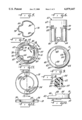
- FIG. 1 is a side view of a faucet assembly of the type described, in part section;
- FIG. 5 is a section along plane 5--5 of FIG. 3;
- FIG. 6 is a rear view of the stand
- FIG. 8 is a section along plane 8--8 of FIG. 7;
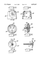
- FIG. 11 is a top view of the escutcheon positioned between the receptor and stand;
- FIG. 15 is a bottom view of the hub
- FIG. 16 is a side view of the hub mounted vacuum breaker
- FIG. 17 is an end view of the vacuum breaker.
- FIG. 18 is a section along plane 18--18 of FIG. 17;
- FIG. 1 illustrates a pullout wand faucet, customarily found in the kitchen and which includes a receptor indicated generally at 10 which has a spout support portion 12 20 which will receive the faucet wand, not shown.
- the hose for the faucet wand is indicated at 14 in broken lines and extends through the faucet assembly from the wand down to the area beneath the sink deck.
- the receptor 10 which may be formed of plastic or of a metallic material, and which will be decorative in nature, encloses the valve body assembly and is mounted for rotation upon a bearing member 16, The bearing member 16 in turn is seated upon an escutcheon 18 which is in the form of a ring, and is illustrated in FIGS. 11and 12. Other forms of escutcheons clearly are acceptable to support the valve assembly shown herein.
- valve body 26 which may contain a single lever valve control cartridge of the type sold by applicant, Moen Incorporated, under the trademark 1225. This cartridge is located within a cylindrical portion 28 of the valve body 26 and will have an upwardly extending stem to which will be connected the cap assembly indicated at 30 and the lever 32. Manipulation of the lever 32 will control the volume and temperature of water supplied through the hose and thus discharged from the faucet wand.
- the escutcheon or ring 18 has a top surface 34 with a pair of limited arcuate slots 36 which slots will receive the downwardly extending arcuate projections 38 on the bottom of the bearing member 16, illustrated in detail in FIGS. 9 and 10 and shown combined with the stand in FIG. 7.
- the bearing member 16 which is preferably formed of plastic to provide electrolytic isolation between the metallic ring or escutcheon 18 and the metallic valve body 26 provides support for rotation of the receptor 10.
- Member 16 has an upstanding vertical wall 42 which has a first portion 44 of a greater vertical height than a second portion 46 with the junction between the portions 44 and 46 forming vertical stops 48 which limit rotation of the receptor 10.
- the member 16 has an outwardly extending circumferential or peripheral flange 50 which provides support for the bottom surface 52 of the receptor 10.
- the receptor 10 may rotate upon the bearing member and its interior surface 54 will contact the stops 48 to limit its rotation.
- rotation of the receptor was customarily limited to approximately 85 degrees.
- spout rotation has been expanded to approximately 145 degrees. This is clearly shown in FIG. 9.
- the bearing member 16 has an arcuate portion 56, illustrated in FIG. 9 and in section in FIG. 8, which has a gradually curved surface 58 which curved surface will face the spout portion 12 of the receptor when the valve assembly is mounted on a sink deck.
- the hose 14 thus has a smooth non-metallic surface over which it will move when the wand is pulled out of the receptor. This is in contrast to prior art structures in which there was no such smooth non-metallic surface for movement of the hose which normally has a metallic outer sheath and thus there was both noise from hose movement and wear on the exterior of the hose.
- the present invention eliminates both the noise and the wear problem by the use of a non-metallic bearing member which has a curved surface over which the hose may move.
- the stand is formed of stainless steel.
- the stand must be inexpensive, but it must withstand the installation load of the faucet body without deforming and thus altering the specific orientation of the valve body.
- Tile stand must have sufficient clearance to allow the hose to move freely when the spout rotates and the material forming the stand should be similar to brass in terms of electromotive force to reduce the potential for corrosion due to electrolytic activity.
- the preferred material for the stand is thus stainless steel.
- the stand has a generally vertical wall 62, the upper end of which has two inwardly extending tabs or projections 64 which will secure the valve body in position by bearing against a portion thereof as shown in FIG. 1. Thus, the upper end of the stand securely holds the valve body in position.
- the stand has two vertical ribs indicated at 66 which not only increase the vertical strength of the stand but provide a shelf at their upper end surfaces 68 for support of the valve body.
- the valve body 26 is held by the tabs 64 and to is seated upon the vertical ribs 66.
- the vertical wall 62 of the stand has a pair of in turned projections 70 which will extend into an annular groove 72 on the exterior of the valve body.
- valve body when assembled, will be pushed down into the stand until the projections 70 snap into the groove 72, thus permanently holding the valve body within the stand.
- the interengagement between the valve body and the stand includes the ribs 66, the tabs 64 and the projections 70, all combining to firmly hold the valve body in position within the stand.
- the lower portion of the stand will interlock with the bearing member 16.
- a rear portion of the stand has a generally horizontally extending projection 74 which is opposite a spout opening 76 in the stand, which opening is there to accommodate movement of the hose.
- the projection 74 will be received within a recess 78 in the bearing member 16, as particularly shown in FIG. 7. This properly aligns the stand with the bearing member and the bearing member, as discussed above, is properly aligned with the escutcheon on the sink deck by the slots 36 and projections 38.
- the lower portion of the stand has a pair of arcuately extending projections 80, shown in FIG.
- a vacuum vent assembly 84 which includes a hub 86 extending over the upper portion of the valve body adjacent to the location of the valve cartridge.
- the area inside of the hub 86 will form a chamber 88 which will receive water discharged from the valve cartridge through outlet port 90.
- the hub 86 as shown in FIGS. 14 and 15 may have three downwardly extending ribs, two of which, indicated at 92 and 94, are positioned closely adjacent to the vacuum breaker 98 to define a vacuum breaker chamber 96.
- the ribs 92 and 94 isolate water discharged from the cartridge, which may contain contamination such as sediment, from the vacuum breaker.
- the vacuum breaker itself is elastomeric in form and has an umbrella portion 108 which masks a group of openings 110 in the wall of the hub 86.
- the umbrella portion 108 will close over the openings 110 so that no water is discharged from the hub.
- the outside of the hub will be at atmospheric pressure.
- the negative pressure from the water supply could draw unclean water from the sink back through the faucet assembly into the water supply.
- the vacuum breaker assembly as if such a negative pressure were to occur, the atmospheric air outside of the hub would force its way inward, pushing the umbrella portion 108 away from the holes 10 and breaking the vacuum, preventing the backward flow of water from the sink through the faucet assembly into the potable water supply.
- valve body which includes the stand and the bearing member.
- the stand is strong, being formed of stainless steel, has supporting vertical ribs, and is made of a material which will reduce electrolytic action between the valve body and the other elements of the assembly, thus lowering the potential for corrosion.
Landscapes
- Health & Medical Sciences (AREA)
- Life Sciences & Earth Sciences (AREA)
- Engineering & Computer Science (AREA)
- Hydrology & Water Resources (AREA)
- Public Health (AREA)
- Water Supply & Treatment (AREA)
- Domestic Plumbing Installations (AREA)
Priority Applications (2)
| Application Number | Priority Date | Filing Date | Title |
|---|---|---|---|
| US09/263,576 US6079447A (en) | 1999-03-08 | 1999-03-08 | Faucet mounting system with improved stand |
| CA002298022A CA2298022C (fr) | 1999-03-08 | 2000-02-01 | Systeme de montage de robinet avec socle ameliore |
Applications Claiming Priority (1)
| Application Number | Priority Date | Filing Date | Title |
|---|---|---|---|
| US09/263,576 US6079447A (en) | 1999-03-08 | 1999-03-08 | Faucet mounting system with improved stand |
Publications (1)
| Publication Number | Publication Date |
|---|---|
| US6079447A true US6079447A (en) | 2000-06-27 |
Family
ID=23002351
Family Applications (1)
| Application Number | Title | Priority Date | Filing Date |
|---|---|---|---|
| US09/263,576 Expired - Lifetime US6079447A (en) | 1999-03-08 | 1999-03-08 | Faucet mounting system with improved stand |
Country Status (2)
| Country | Link |
|---|---|
| US (1) | US6079447A (fr) |
| CA (1) | CA2298022C (fr) |
Cited By (27)
| Publication number | Priority date | Publication date | Assignee | Title |
|---|---|---|---|---|
| US6311729B1 (en) * | 2000-04-24 | 2001-11-06 | Moen Incorporated | Kitchen faucet spout retainer |
| US20030140413A1 (en) * | 2000-03-09 | 2003-07-31 | Gerhard Ginter | Sanitary appliance |
| US6779549B2 (en) | 2002-10-28 | 2004-08-24 | Moen Incorporated | In-line vacuum breaker |
| US20060157127A1 (en) * | 2005-01-14 | 2006-07-20 | Bors Mark S | Swing spout having a rotational detent |
| US20070023094A1 (en) * | 2005-07-29 | 2007-02-01 | Young Wu C | Faucet |
| US20070044852A1 (en) * | 2005-08-29 | 2007-03-01 | Thomas Pinette | Waterway connection |
| US20070157981A1 (en) * | 2006-01-12 | 2007-07-12 | Burns Leonard J | Rigid mounting system for swing spouts |
| US20080178935A1 (en) * | 2007-01-31 | 2008-07-31 | Masco Corporation Of Indiana | Diverter integrated into a side sprayer |
| USD574402S1 (en) | 2007-10-03 | 2008-08-05 | Nasco Corporation Of Indiana | Waterway |
| US7415991B2 (en) | 2005-12-20 | 2008-08-26 | Masco Corporation Of Indiana | Faucet spout with water isolating couplings |
| US20090020177A1 (en) * | 2006-05-26 | 2009-01-22 | Masco Corporation Of Indiana | Valve mounting assembly |
| USD587785S1 (en) | 2007-10-03 | 2009-03-03 | Masco Corporation Of Indiana | Waterway |
| US7717133B2 (en) | 2007-01-31 | 2010-05-18 | Masco Corporation Of Indiana | Spout tip attachment |
| US7748409B2 (en) | 2007-01-31 | 2010-07-06 | Masco Corporation Of Indiana | Overmold interface for fluid carrying system |
| US7806141B2 (en) | 2007-01-31 | 2010-10-05 | Masco Corporation Of Indiana | Mixing valve including a molded waterway assembly |
| US20100282349A1 (en) * | 2009-05-08 | 2010-11-11 | Esche John C | Corrosion Resistant Faucets With Components Made Of Different Metallic Materials |
| US20110061754A1 (en) * | 2008-05-21 | 2011-03-17 | Thomas Kurt J | Integrated kitchen faucet side spray and diverter |
| US20110100494A1 (en) * | 2009-11-05 | 2011-05-05 | Ruifu Wang | Rotary Pulling Tap |
| US8104512B2 (en) | 2008-09-25 | 2012-01-31 | Masco Corporation Of Indiana | Spout tip retention method |
| US8695625B2 (en) | 2008-06-25 | 2014-04-15 | Masco Corporation Of Indiana | Centerset faucet with mountable spout |
| US8739826B2 (en) | 2011-03-11 | 2014-06-03 | Masco Corporation Of Indiana | Centerset faucet body and method of making same |
| US8931500B2 (en) | 2012-02-17 | 2015-01-13 | Masco Corporation Of Indiana | Two handle centerset faucet |
| US8991425B2 (en) | 2006-05-26 | 2015-03-31 | Delta Faucet Company | Waterway assembly including an overmolded support plate |
| US9151397B2 (en) | 2008-04-10 | 2015-10-06 | Delta Faucet Company | Molded waterway for a two handle faucet |
| US20170101765A1 (en) * | 2015-10-10 | 2017-04-13 | Xiamen Runner Industrial Corporation | Faucet main body fast detaching and replacing mehhod, and faucet structure for implementing the same |
| US9689147B2 (en) * | 2015-07-13 | 2017-06-27 | Delta Faucet Company | Snap in mounting shank for a faucet |
| US20180155905A1 (en) * | 2016-12-02 | 2018-06-07 | Moen Incorporated | Pullout faucet with mounting system |
Citations (12)
| Publication number | Priority date | Publication date | Assignee | Title |
|---|---|---|---|---|
| US2878489A (en) * | 1958-02-27 | 1959-03-24 | Wilson B Graham | Mixing faucet fitting |
| US4456287A (en) * | 1982-01-15 | 1984-06-26 | Elkay Manufacturing Company | Rotary coupling |
| US4592388A (en) * | 1985-02-11 | 1986-06-03 | Indiana Brass, Inc. | Connector assembly for swivel type faucet spout |
| US4827538A (en) * | 1986-02-05 | 1989-05-09 | Friedrich Grohe Armaturenfabrik | Mixing fixture for flexible-pipe spray head |
| US4856122A (en) * | 1988-03-28 | 1989-08-15 | Sloan Valve Company | Anti-rotation device |
| US4856121A (en) * | 1986-05-23 | 1989-08-15 | Traylor Paul L | Air gap faucet |
| US4997008A (en) * | 1990-04-26 | 1991-03-05 | Moen Incorporated | Faucet spout assembly |
| US5349987A (en) * | 1994-01-24 | 1994-09-27 | Shieh Ming Dang | Faucet with a movable extension nozzle |
| US5381830A (en) * | 1994-01-18 | 1995-01-17 | Masco Corporation Of Indiana | Spout mounting system |
| US5388287A (en) * | 1993-07-12 | 1995-02-14 | Ecowater Systems, Inc. | Countertop faucet assembly |
| US5535776A (en) * | 1995-05-15 | 1996-07-16 | Moen Incorporated | Kitchen faucet top mount device |
| US5575424A (en) * | 1994-10-20 | 1996-11-19 | Kohler Co. | Vacuum breaker for faucets |
-
1999
- 1999-03-08 US US09/263,576 patent/US6079447A/en not_active Expired - Lifetime
-
2000
- 2000-02-01 CA CA002298022A patent/CA2298022C/fr not_active Expired - Fee Related
Patent Citations (12)
| Publication number | Priority date | Publication date | Assignee | Title |
|---|---|---|---|---|
| US2878489A (en) * | 1958-02-27 | 1959-03-24 | Wilson B Graham | Mixing faucet fitting |
| US4456287A (en) * | 1982-01-15 | 1984-06-26 | Elkay Manufacturing Company | Rotary coupling |
| US4592388A (en) * | 1985-02-11 | 1986-06-03 | Indiana Brass, Inc. | Connector assembly for swivel type faucet spout |
| US4827538A (en) * | 1986-02-05 | 1989-05-09 | Friedrich Grohe Armaturenfabrik | Mixing fixture for flexible-pipe spray head |
| US4856121A (en) * | 1986-05-23 | 1989-08-15 | Traylor Paul L | Air gap faucet |
| US4856122A (en) * | 1988-03-28 | 1989-08-15 | Sloan Valve Company | Anti-rotation device |
| US4997008A (en) * | 1990-04-26 | 1991-03-05 | Moen Incorporated | Faucet spout assembly |
| US5388287A (en) * | 1993-07-12 | 1995-02-14 | Ecowater Systems, Inc. | Countertop faucet assembly |
| US5381830A (en) * | 1994-01-18 | 1995-01-17 | Masco Corporation Of Indiana | Spout mounting system |
| US5349987A (en) * | 1994-01-24 | 1994-09-27 | Shieh Ming Dang | Faucet with a movable extension nozzle |
| US5575424A (en) * | 1994-10-20 | 1996-11-19 | Kohler Co. | Vacuum breaker for faucets |
| US5535776A (en) * | 1995-05-15 | 1996-07-16 | Moen Incorporated | Kitchen faucet top mount device |
Cited By (52)
| Publication number | Priority date | Publication date | Assignee | Title |
|---|---|---|---|---|
| US20030140413A1 (en) * | 2000-03-09 | 2003-07-31 | Gerhard Ginter | Sanitary appliance |
| US6868564B2 (en) * | 2000-03-09 | 2005-03-22 | Hansgrohe Ag | Sanitary fitting, particularly kitchen mixer |
| US6311729B1 (en) * | 2000-04-24 | 2001-11-06 | Moen Incorporated | Kitchen faucet spout retainer |
| US6779549B2 (en) | 2002-10-28 | 2004-08-24 | Moen Incorporated | In-line vacuum breaker |
| US20060157127A1 (en) * | 2005-01-14 | 2006-07-20 | Bors Mark S | Swing spout having a rotational detent |
| US20070023094A1 (en) * | 2005-07-29 | 2007-02-01 | Young Wu C | Faucet |
| US20070044852A1 (en) * | 2005-08-29 | 2007-03-01 | Thomas Pinette | Waterway connection |
| US8464748B2 (en) | 2005-08-29 | 2013-06-18 | Masco Corporation Of Indiana | Waterway connection |
| US7406980B2 (en) | 2005-08-29 | 2008-08-05 | Masco Corporation Of Indiana | Waterway connection |
| US7793677B2 (en) | 2005-08-29 | 2010-09-14 | Masco Corporation Of Indiana | Waterway connection |
| US20110005624A1 (en) * | 2005-08-29 | 2011-01-13 | Thomas Pinette | Waterway connection |
| US7415991B2 (en) | 2005-12-20 | 2008-08-26 | Masco Corporation Of Indiana | Faucet spout with water isolating couplings |
| US20080308165A1 (en) * | 2005-12-20 | 2008-12-18 | Steven Kyle Meehan | Faucet spout with water isolating couplings |
| US7992590B2 (en) | 2005-12-20 | 2011-08-09 | Masco Corporation Of Indiana | Faucet spout with water isolating couplings |
| US20070157981A1 (en) * | 2006-01-12 | 2007-07-12 | Burns Leonard J | Rigid mounting system for swing spouts |
| US8985146B2 (en) | 2006-05-26 | 2015-03-24 | Delta Faucet Company | Faucet including a molded waterway assembly |
| US8991425B2 (en) | 2006-05-26 | 2015-03-31 | Delta Faucet Company | Waterway assembly including an overmolded support plate |
| US8365770B2 (en) | 2006-05-26 | 2013-02-05 | Masco Corporation Of Indiana | Faucet including a molded waterway assembly |
| US20090020177A1 (en) * | 2006-05-26 | 2009-01-22 | Masco Corporation Of Indiana | Valve mounting assembly |
| US9951880B2 (en) | 2006-05-26 | 2018-04-24 | Delta Faucet Company | Faucet including a molded waterway assembly |
| US7766043B2 (en) | 2006-05-26 | 2010-08-03 | Masco Corporation Of Indiana | Faucet including a molded waterway assembly |
| US7819137B2 (en) | 2006-05-26 | 2010-10-26 | Masco Corporation Of Indiana | Valve mounting assembly |
| US20080178935A1 (en) * | 2007-01-31 | 2008-07-31 | Masco Corporation Of Indiana | Diverter integrated into a side sprayer |
| US7806141B2 (en) | 2007-01-31 | 2010-10-05 | Masco Corporation Of Indiana | Mixing valve including a molded waterway assembly |
| US7748409B2 (en) | 2007-01-31 | 2010-07-06 | Masco Corporation Of Indiana | Overmold interface for fluid carrying system |
| US7721761B2 (en) | 2007-01-31 | 2010-05-25 | Masco Corporation Of Indiana | Diverter integrated into a side sprayer |
| US7717133B2 (en) | 2007-01-31 | 2010-05-18 | Masco Corporation Of Indiana | Spout tip attachment |
| US8469056B2 (en) | 2007-01-31 | 2013-06-25 | Masco Corporation Of Indiana | Mixing valve including a molded waterway assembly |
| USD611571S1 (en) | 2007-10-03 | 2010-03-09 | Masco Corporation Of Indiana | Waterway |
| USD591320S1 (en) | 2007-10-03 | 2009-04-28 | Masco Corporation Of Indiana | Waterway |
| USD587785S1 (en) | 2007-10-03 | 2009-03-03 | Masco Corporation Of Indiana | Waterway |
| USD574402S1 (en) | 2007-10-03 | 2008-08-05 | Nasco Corporation Of Indiana | Waterway |
| US9151397B2 (en) | 2008-04-10 | 2015-10-06 | Delta Faucet Company | Molded waterway for a two handle faucet |
| US20110061754A1 (en) * | 2008-05-21 | 2011-03-17 | Thomas Kurt J | Integrated kitchen faucet side spray and diverter |
| US9243389B2 (en) | 2008-05-21 | 2016-01-26 | Delta Faucet Company | Integrated kitchen faucet side spray and diverter |
| US8646476B2 (en) | 2008-05-21 | 2014-02-11 | Masco Corporation Of Indiana | Integrated kitchen faucet side spray and diverter |
| US8695625B2 (en) | 2008-06-25 | 2014-04-15 | Masco Corporation Of Indiana | Centerset faucet with mountable spout |
| US8590572B2 (en) | 2008-09-25 | 2013-11-26 | Masco Corporation Of Indiana | Spout tip retention method |
| US8104512B2 (en) | 2008-09-25 | 2012-01-31 | Masco Corporation Of Indiana | Spout tip retention method |
| US8863780B2 (en) | 2009-05-08 | 2014-10-21 | Kohler Co. | Corrosion resistant faucets with components made of different metallic materials |
| US20100282349A1 (en) * | 2009-05-08 | 2010-11-11 | Esche John C | Corrosion Resistant Faucets With Components Made Of Different Metallic Materials |
| US8375993B2 (en) | 2009-05-08 | 2013-02-19 | Kohler Co. | Corrosion resistant faucets with components made of different metallic materials |
| US8403005B2 (en) * | 2009-11-05 | 2013-03-26 | Globe Union Industrial Corp. | Rotary pulling tap |
| US20110100494A1 (en) * | 2009-11-05 | 2011-05-05 | Ruifu Wang | Rotary Pulling Tap |
| US8739826B2 (en) | 2011-03-11 | 2014-06-03 | Masco Corporation Of Indiana | Centerset faucet body and method of making same |
| US9403304B2 (en) | 2011-03-11 | 2016-08-02 | Delta Faucet Company | Centerset faucet body and method of making same |
| US8931500B2 (en) | 2012-02-17 | 2015-01-13 | Masco Corporation Of Indiana | Two handle centerset faucet |
| US9689147B2 (en) * | 2015-07-13 | 2017-06-27 | Delta Faucet Company | Snap in mounting shank for a faucet |
| US20170101765A1 (en) * | 2015-10-10 | 2017-04-13 | Xiamen Runner Industrial Corporation | Faucet main body fast detaching and replacing mehhod, and faucet structure for implementing the same |
| US20180155905A1 (en) * | 2016-12-02 | 2018-06-07 | Moen Incorporated | Pullout faucet with mounting system |
| US10006190B1 (en) * | 2016-12-02 | 2018-06-26 | Moen Incorporated | Pullout faucet with mounting system |
| US10858812B2 (en) | 2016-12-02 | 2020-12-08 | Fb Global Plumbing Group Llc | Pullout faucet with mounting system |
Also Published As
| Publication number | Publication date |
|---|---|
| CA2298022C (fr) | 2003-04-08 |
| CA2298022A1 (fr) | 2000-09-08 |
Similar Documents
| Publication | Publication Date | Title |
|---|---|---|
| US6079447A (en) | Faucet mounting system with improved stand | |
| US6070614A (en) | Faucet mounting system with improved bearing support | |
| KR900004457B1 (ko) | 전환 밸브 | |
| US9200435B2 (en) | Retainer assembly for swivel spout | |
| US11001994B2 (en) | Reduced profile faucet handle assembly | |
| US7658202B2 (en) | Low-profile valve assembly | |
| US5575424A (en) | Vacuum breaker for faucets | |
| US5361431A (en) | Vacuum breaker for faucets | |
| CN100457289C (zh) | 用于喷头的转座、液流传送装配体和喷淋装配体 | |
| US8074675B2 (en) | Faucet handle mounting | |
| US4037624A (en) | Spout assembly | |
| EP0380117A2 (fr) | Soupape de diversion et soupape de ventilation pour celle-ci | |
| US11511304B2 (en) | Shower column assembly | |
| US5743291A (en) | Sanitary safety device | |
| US6125875A (en) | Pullout faucet value body with integral vacuum breaker hub | |
| CA2674419A1 (fr) | Accessoire de dessous de cartouche | |
| US20180195628A1 (en) | Faucet with multi-directional controls | |
| US7926508B2 (en) | Water control valve system with snapping action | |
| US20240384512A1 (en) | Dual handle center mounted faucet | |
| US4757841A (en) | Spout with readily serviceable flow control | |
| KR102341283B1 (ko) | 경량 구조를 갖는 수전 | |
| US12601430B2 (en) | Shower column assembly | |
| EP1407087B2 (fr) | Dispositif sanitaire dote d'un mitigeur a trou mecanique unique pour surface horizontale | |
| CN121368664A (zh) | 水龙头组件 | |
| CN220770299U (zh) | 一种暗装淋浴龙头 |
Legal Events
| Date | Code | Title | Description |
|---|---|---|---|
| AS | Assignment |
Owner name: MOEN INCORPORATED, OHIO Free format text: ASSIGNMENT OF ASSIGNORS INTEREST;ASSIGNOR:ROTH, MARK W.;REEL/FRAME:009824/0379 Effective date: 19990223 Owner name: MOEN INCORPORATED, OHIO Free format text: ASSIGNMENT OF ASSIGNORS INTEREST;ASSIGNORS:HOLZHEIMER, JOHN C.;NASR, NAGIB;REEL/FRAME:009824/0386 Effective date: 19990223 |
|
| STCF | Information on status: patent grant |
Free format text: PATENTED CASE |
|
| FEPP | Fee payment procedure |
Free format text: PAYOR NUMBER ASSIGNED (ORIGINAL EVENT CODE: ASPN); ENTITY STATUS OF PATENT OWNER: LARGE ENTITY |
|
| FPAY | Fee payment |
Year of fee payment: 4 |
|
| FPAY | Fee payment |
Year of fee payment: 8 |
|
| REMI | Maintenance fee reminder mailed | ||
| FPAY | Fee payment |
Year of fee payment: 12 |