US6089532A - Valve for use with agricultural sprayers - Google Patents
Valve for use with agricultural sprayers Download PDFInfo
- Publication number
- US6089532A US6089532A US09/022,577 US2257798A US6089532A US 6089532 A US6089532 A US 6089532A US 2257798 A US2257798 A US 2257798A US 6089532 A US6089532 A US 6089532A
- Authority
- US
- United States
- Prior art keywords
- valve
- diaphragm
- piston
- inlet
- piece
- Prior art date
- Legal status (The legal status is an assumption and is not a legal conclusion. Google has not performed a legal analysis and makes no representation as to the accuracy of the status listed.)
- Expired - Fee Related
Links
- 239000012530 fluid Substances 0.000 claims abstract description 52
- 238000007789 sealing Methods 0.000 claims description 25
- 238000005507 spraying Methods 0.000 description 25
- 239000000126 substance Substances 0.000 description 12
- 239000007921 spray Substances 0.000 description 7
- 239000000463 material Substances 0.000 description 5
- -1 buna Polymers 0.000 description 2
- 238000006073 displacement reaction Methods 0.000 description 2
- 239000000428 dust Substances 0.000 description 2
- 239000003337 fertilizer Substances 0.000 description 2
- 239000004009 herbicide Substances 0.000 description 2
- 230000002093 peripheral effect Effects 0.000 description 2
- 239000000575 pesticide Substances 0.000 description 2
- 229920002635 polyurethane Polymers 0.000 description 2
- 239000004814 polyurethane Substances 0.000 description 2
- 230000003068 static effect Effects 0.000 description 2
- 229920002449 FKM Polymers 0.000 description 1
- 239000004743 Polypropylene Substances 0.000 description 1
- 239000004699 Ultra-high molecular weight polyethylene Substances 0.000 description 1
- 239000003905 agrochemical Substances 0.000 description 1
- 230000004323 axial length Effects 0.000 description 1
- 230000006835 compression Effects 0.000 description 1
- 238000007906 compression Methods 0.000 description 1
- 239000000356 contaminant Substances 0.000 description 1
- 238000011109 contamination Methods 0.000 description 1
- 230000001419 dependent effect Effects 0.000 description 1
- 229920001971 elastomer Polymers 0.000 description 1
- 230000001747 exhibiting effect Effects 0.000 description 1
- 238000009313 farming Methods 0.000 description 1
- 239000004519 grease Substances 0.000 description 1
- 238000005461 lubrication Methods 0.000 description 1
- 238000004519 manufacturing process Methods 0.000 description 1
- 239000004033 plastic Substances 0.000 description 1
- 229920003023 plastic Polymers 0.000 description 1
- 229920001084 poly(chloroprene) Polymers 0.000 description 1
- 229920001155 polypropylene Polymers 0.000 description 1
- 239000004810 polytetrafluoroethylene Substances 0.000 description 1
- 229920001343 polytetrafluoroethylene Polymers 0.000 description 1
- 239000002689 soil Substances 0.000 description 1
- 229920000785 ultra high molecular weight polyethylene Polymers 0.000 description 1
Images


Classifications
-
- F—MECHANICAL ENGINEERING; LIGHTING; HEATING; WEAPONS; BLASTING
- F16—ENGINEERING ELEMENTS AND UNITS; GENERAL MEASURES FOR PRODUCING AND MAINTAINING EFFECTIVE FUNCTIONING OF MACHINES OR INSTALLATIONS; THERMAL INSULATION IN GENERAL
- F16K—VALVES; TAPS; COCKS; ACTUATING-FLOATS; DEVICES FOR VENTING OR AERATING
- F16K7/00—Diaphragm valves or cut-off apparatus, e.g. with a member deformed, but not moved bodily, to close the passage ; Pinch valves
- F16K7/12—Diaphragm valves or cut-off apparatus, e.g. with a member deformed, but not moved bodily, to close the passage ; Pinch valves with flat, dished, or bowl-shaped diaphragm
- F16K7/14—Diaphragm valves or cut-off apparatus, e.g. with a member deformed, but not moved bodily, to close the passage ; Pinch valves with flat, dished, or bowl-shaped diaphragm arranged to be deformed against a flat seat
- F16K7/17—Diaphragm valves or cut-off apparatus, e.g. with a member deformed, but not moved bodily, to close the passage ; Pinch valves with flat, dished, or bowl-shaped diaphragm arranged to be deformed against a flat seat the diaphragm being actuated by fluid pressure
-
- F—MECHANICAL ENGINEERING; LIGHTING; HEATING; WEAPONS; BLASTING
- F16—ENGINEERING ELEMENTS AND UNITS; GENERAL MEASURES FOR PRODUCING AND MAINTAINING EFFECTIVE FUNCTIONING OF MACHINES OR INSTALLATIONS; THERMAL INSULATION IN GENERAL
- F16K—VALVES; TAPS; COCKS; ACTUATING-FLOATS; DEVICES FOR VENTING OR AERATING
- F16K31/00—Actuating devices; Operating means; Releasing devices
- F16K31/12—Actuating devices; Operating means; Releasing devices actuated by fluid
- F16K31/126—Actuating devices; Operating means; Releasing devices actuated by fluid the fluid acting on a diaphragm, bellows, or the like
- F16K31/1268—Actuating devices; Operating means; Releasing devices actuated by fluid the fluid acting on a diaphragm, bellows, or the like with a plurality of the diaphragms
Definitions
- the present invention relates generally to the field of valves. More particularly, the present invention relates to diaphragm valves for use with agricultural sprayers.
- Such spraying equipment often includes a mobile unit such as a tractor equipped with a large tank for carrying the chemicals desired to be sprayed.
- the chemicals are typically pumped from the tank through flow lines to a plurality of spray nozzles that are typically mounted on an elongated boom structure pulled behind the mobile vehicle.
- Flow through the spray nozzles is typically controlled by mechanical spring valves that stop flow to the spray nozzles when the pressure in the flow lines falls below a predetermined level.
- a problem with such mechanical spring valves is that they typically do not have the capability of instantaneously stopping and starting a uniform discharge through the spray nozzles. This lack of control is particularly problematic at the ends of fields where spraying must be temporarily stopped and restarted as the spraying equipment turns to make subsequent passes across the field.
- pneumatically actuated valves for controlling flow through the spray nozzles. Two different types of pneumatic valves have been utilized: normally open; and normally closed.
- a normally open valve uses a heavy spring to hold the valve open, and relies on air pressure to push the valve closed.
- a normally closed valve uses a heavy spring to hold the valve closed, and relies on air pressure to open the valve.
- valves A variety of problems exist with respect to the above identified valves. For example, one problem relates to such valves' dependence upon a source of compressed air such as an air compressor. If the air compressor fails, a normally open valve will have no way of preventing the undesirable leakage of chemicals from the spraying equipment. By contrast, if the air compressor fails in a system utilizing normally closed valves, the spraying equipment is completely inoperative.
- a source of compressed air such as an air compressor.
- valve arrangements typically have a sealed piston that slides within the valve.
- displacement areas within the valve are vented to the outside atmosphere to eliminate the compression of gasses within the valve as the piston moves.
- a valve that vents to atmosphere rapidly becomes contaminated with dirt. Such dirt both damages the piston seals and increases friction within the valve.
- the pistons are commonly lubricated with grease that rapidly entraps field dust and further intensifies the problem of contamination induced friction and wear.
- One possible embodiment of the present invention relates to a valve including a valve body defining an inlet port and an outlet port.
- the valve also includes a first diaphragm arranged and configured for opening and closing a fluid flow path between the inlet and outlet ports.
- the valve further includes a second diaphragm cooperating with the first diaphragm to enclose a chamber formed within the valve body. The valve is closed by applying an actuating pressure to an exterior side of the second diaphragm such that the first diaphragm is caused to close the fluid flow path between the inlet and outlet ports.
- a piston structure is positioned within the chamber between the first and second diaphragms such that when the actuating pressure is applied to the second diaphragm, the second diaphragm forces the piston structure against the first diaphragm causing the first diaphragm to close the valve.
- the two diaphragm configuration eliminates the need for internal sliding pistons thereby reducing or minimizing friction within the valve and eliminating the need for lubrication.
- the embodiment does not require a spring for holding the valve open. Consequently, a large percentage of the closing force provided by the actuating pressure can be transferred to the first diaphragm because there is no substantial spring resistance that needs to be overcome.
- the embodiment does not need its displacement area to be vented to atmosphere. Hence, wear of the valve is reduced because dust and other contaminants prevalent in farming environments are not drawn into the valve. Furthermore, the valve is relatively easy to assemble and manufacture.
- a valve including a sealing element moveable between a first position in which a fluid flow path between inlet and outlet ports of the valve is open, and a second position in which the fluid flow path between the inlet and outlet ports is closed.
- the valve also includes a first valve closing structure arranged and configured to move the sealing element to the second position when an actuating pressure is supplied to the first valve closing structure by a source of fluid pressure.
- the valve further includes a second valve closing structure arranged and configured to resiliently bias the sealing element toward the second position.
- the second valve closing structure can function as a mechanical "back-up" for closing the valve even if the source of fluid pressure, such as an air compressor, becomes inoperative. Consequently, if a fluid pressure failure occurs, the valve continues to operate thereby allowing a user of the valve to continue operations such as agricultural spraying.
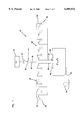
- FIG. 1 is a schematic drawing of an agricultural spraying configuration incorporating valves constructed in accordance with the principles of the present invention
- FIG. 2 is a cross-sectional view of a valve constructed in accordance with the principles of the present invention, the valve is shown in an open position;
- FIG. 3 is a cross-sectional view of the valve of FIG. 2, the valve is shown in a pneumatically closed position;
- FIG. 4 is a cross-sectional view of the valve of FIG. 2, the valve is shown in a mechanically closed position;
- FIG. 5 is a cross-sectional view of a first alternate embodiment constructed in accordance with the principles of the present invention.
- FIG. 6 is a cross-sectional view of a second alternate embodiment constructed in accordance with the principles of the present invention.
- One such broad aspect relates to a valve that is not vented to atmosphere.
- Another broad aspect relates to a valve having minimal internal friction.
- An additional broad aspect relates to a valve having an actuating diaphragm that cooperates with a sealing diaphragm to open and close the valve.
- a further broad aspect relates to a valve having structure for pneumatically or hydraulically closing the valve, and a "back-up" structure for resiliently or mechanically closing the valve.
- FIG. 1 is a schematic illustration of a agricultural spraying arrangement 20 incorporating valves 22 constructed in accordance with the principles of the present invention.
- the spraying arrangement 20 includes a tank 24, a pump 25, a boom structure 26 having a plurality of spray nozzles 28, and a source of compressed fluid such as an air compressor 30.
- the tank 24 typically contains agricultural chemicals such as herbicides, pesticides and fertilizers that are pumped through a pair of flow lines 32 to the nozzles 28. Flow through the individual flow lines 32 is controlled by a master pump valve 34, while flow through the individual nozzles 28 is controlled by the valves 22.
- the valves 22 are selectively pneumatically closed through the use of air pressure provided by the air compressor 30.
- the compressed air is directed to the valves 22 through a pair of flow lines 36 typically made of hosing, piping, tubing or other type of conduit suitable for conveying fluid.
- a pair of air solenoids 38 control flow through the flow lines 36, while the air pressure provided by the air compressor 30 is controlled by a regulator 40.
- the spraying arrangement 20 is typically coupled to a vehicle, such as a tractor, adapted for pulling the spraying arrangement 20 across a farm field.
- a vehicle such as a tractor
- the nozzles 28 deliver a controlled amount of chemicals to the soil.
- the valves 22 are pneumatically closed thereby stopping flow through the nozzles 28 while the tractor turns around for another pass across the field. Because the valves 22 are pneumatically actuated, flow through the nozzles 28 can be stopped almost instantaneously. Also, because the valves are located directly adjacent to the nozzles 28, constant pressure is maintained in the flow lines 32 even when the valves 22 are closed. Hence, after the tractor turns around and the valves 22 are re-opened, a desired uniform spraying concentration/rate can almost instantaneous be achieved at each of the nozzles 28.
- FIGS. 2-4 are cross-sectional views taken lengthwise through one of the valves 22.
- the valve 22 includes a valve body 42 defining an inlet port 44 and an outlet port 46.
- the valve 22 also includes a first diaphragm 48 moveable between a first position in which a fluid flow path 49 between the inlet and outlet ports 44 and 46 is open (shown in FIG. 2), and a second position in which the fluid flow path 49 between the inlet and outlet ports 44 and 46 is closed (shown in FIG. 3).
- the valve 22 also includes a second diaphragm 50 cooperating with the first diaphragm 48 to enclose a sealed chamber 52 formed within the valve body 42.
- a piston structure 43 is positioned within the chamber 52 between the first and second diaphragms 48 and 50.
- the second diaphragm 50 drives the piston structure 43 against the first diaphragm 48 causing the first diaphragm 48 to be mechanically moved such that the fluid flow path 49 between the inlet and outlet ports 44 and 46 is closed.
- the valve body 42 of the valve 22 includes a first end piece 56, a second end piece 58 and an intermediate piece 60 positioned between the first and second end pieces 56 and 58.
- the first end piece 56, the second end piece 58 and the intermediate piece 60 are threaded together. More specifically, the first end piece 56 is threaded within the intermediate piece 60, and the intermediate piece 60 is threaded within the second end piece 58.
- the first diaphragm 48 is positioned between the first end piece 56 and the intermediate piece 60, and the second diaphragm 50 is positioned between the second end piece 58 and the intermediate piece 60.
- a peripheral or circumferential portion 62 of the first diaphragm 48 is clamped between the first end piece 56 and the intermediate piece 60 to form an annular static seal between the pieces.
- a peripheral or circumferential portion 64 of the second diaphragm 50 is clamped between the second end piece 58 and the intermediate piece 60 to form an annular static seal between the pieces.
- the intermediate piece 60 of the valve body 42 is generally cylindrical or tubular and defines the chamber 52 of the valve 22. Opposite ends of the chamber 52 are enclosed and sealed by the first and second diaphragms 48 and 50.
- the diaphragms 48 and 50 are generally thin-cylinder or disk-shaped and are preferably made of a resilient or flexible material such as polyurethane, neoprene, buna, viton, or other rubber or plastic materials.
- the diaphragms 48 and 50 can also be made of multiple layers of different materials to achieve desired flexibility characteristics.
- the first diaphragm 48 includes an inner layer 66 made of polyurethane and an outer layer 68 made of ultra high molecular weight polyethylene.
- outer layer 66 Other illustrative materials suitable for forming the outer layer 66 include PTFE and polypropylene.
- outer diaphragm 68 is shown having two layers, it will be appreciated that the diaphragm could also have one layer or more than two layers depending upon the flexibility characteristics of the particular materials employed.
- the first end piece 56 of the valve body 42 defines the inlet and outlet ports 44 and 46.
- the outlet port 46 is formed by a centrally located first opening that extends axially through the first end piece 56.
- the inlet port 48 is formed by an annular second axial opening defined by the first end piece 56 that is radially offset from and co-axially aligned with the first axial opening.
- the inlet port 48 is shown as an outer opening and the outlet port 46 is shown as an inner opening, it will be appreciated that fluid can also be pumped through the valve in the reverse direction such that the inlet and outlet openings are reversed. The determination of whether a particular port is an inlet or outlet port is dependent upon the flow arrangement of the structure to which the valve is coupled.
- the first end piece 56 also includes an internally threaded female portion 70 adapted for connection to a corresponding threaded male piece of a fluid connector.
- a fluid connector would typically be associated with fluid conduit such as the flow lines 32 of the spraying arrangement 20.
- An outer annular seal or O-ring 72 is positioned within the female portion 70 to prevent leakage between the valve 22 and a fluid connector threaded within the female portion 70.
- An inner annular seal or O-ring 74 is also positioned within the female portion 70 to prevent cross-flow between the inlet and outlet ports 44 and 46 when a fluid connector is threaded within the female portion 70.
- the second end piece 58 of the valve body 42 is adapted for connection to a source of fluid pressure, such as the air compressor 30, for supplying the actuating pressure to the second diaphragm 50.
- a source of fluid pressure such as the air compressor 30, for supplying the actuating pressure to the second diaphragm 50.
- the second end piece 58 includes an elongated tubular portion 76 and a flared portion 78.
- the tubular portion 76 and the flared portion 78 cooperate to define a fluid or air passage 80 in fluid communication with the exterior side 54 of the second diaphragm 50.
- the air passage 80 has a relatively small cross-sectional area along the tubular portion 76 and has a relatively large cross-sectional area adjacent the second diaphragm 50.
- the source of fluid pressure is connected to the valve 22 by means such as flexible tubing that is inserted over the tubular portion 76 of the second end piece 58.
- the first and second diaphragms 48 and 50 are generally coaxially aligned.
- the second diaphragm 50 preferably has a larger surface area than the first diaphragm 48. More preferably the second diaphragm 50 has a surface area two or three times as large as the surface area of the first diaphragm 48.
- a 50 pound per square inch (psi) pressure applied to the second diaphragm 50 generates a sealing pressure of roughly 150 psi at the first diaphragm 48.
- the ability to generate a sealing pressure that is greater than the actuation pressure applied to the second diaphragm 50 is significant because air compressors commonly have pressure limits slightly above 100 psi, and it is foreseeable that spraying pressures may exceed 100 psi in the future.
- the valve 22 of FIGS. 2-4 also includes an optional spring structure 82 arranged and configured to bias the first diaphragm 48 toward a position in which the fluid flow path 49 between the inlet and outlet ports 44 and 46 is closed.
- the spring structure 82 is a coil spring mounted within the chamber 52 between the first and second diaphragms 48 and 50.
- the term "spring structure” also includes other structures exhibiting spring-like characteristics such as elastomeric structures, elastic structures, and resilient structures.
- the spring structure 82 is adapted to function as a mechanical back-up for closing the valve 22 if the source of actuating pressure becomes inoperative.
- FIG. 4 shows the valve 22 with only the spring structure 82 holding the first diaphragm 48 in the closed position.
- the spring structure 82 does not need a high force to close fluid flow path 49 since the spring need only overcome the elastic memory of the first diaphragm 48.
- the spring structure 82 generates a sealing pressure of about 5 psi. This relatively low spring force allows the fluid flow path 49 to be forced open at relatively low pressures, but prevents dripping, drainage or other flow through the valve 22 when the pressure along the fluid flow line 49 falls below the sealing pressure applied by the spring structure 82. Consequently, when used in association with an agricultural sprayer, an operator can continue spraying even if the operator's actuating pressure source fails.
- the piston structure 43 can include one or more pieces or members mounted within the chamber 52 and adapted for transferring a closing force from the second diaphragm 50 to the first diaphragm 48.
- the piston structure 43 is preferably adapted for telescopic movement within the valve body 42.
- the pistons structure 43 includes a first end cap 84 and a second end cap 86.
- the spring structure 82 of the valve 22 has one end mounted in a recess defined by the first end cap 84 and the other end mounted in a recess defined by the second end cap 86.
- the first end cap 84 includes a substantially flat end 88 that engages an interior surface of the first diaphragm 48, while the second end cap 86 includes a surface 90 (preferably convex) that engages an interior surface of the second diaphragm 50.
- the second end cap 86 is mounted for limited telescopic movement within the intermediate piece 60 of the valve body 42, while the first end cap 84 is mounted for limited telescopic movement within the recess of the second end cap 86.
- the first end cap 84 has an axial length that is less that the depth of the recess defined by the second end cap 86 such that when the valve is closed, the end caps 84 and 86 contact one another.
- the valve 22 is assembled by first placing the first diaphragm 48 between the first end piece 56 and the intermediate piece 60 of the valve body 42, and then threading the first end piece 56 within the intermediate piece 60 until the first diaphragm 48 is circumferentially clamped. Next, the second diaphragm 50, the second cap 86, the spring structure 82 and the first cap 84 are co-axially aligned between the second end piece 58 and the intermediate piece 60 of the valve body 42.
- the intermediate piece 60 is threaded into the second end piece 58 until the second diaphragm 50 is circumferentially clamped and the second cap 86, the spring structure 82 and the first cap 84 are captured within the intermediate piece 60 between the first and second diaphragms 48 and 50.
- valve 22 The operation of the valve 22 will now be described as it would be used in association with the spraying arrangement 20 of FIG. 1. However, it will be appreciated that the valve 22 can be used in other systems for controlling flow and is not limited to agricultural spraying systems.
- the valve 22 controls flow between one of the chemical flow lines 32 and one of the nozzles 28.
- the female portion 70 of the valve 22 is connected to the chemical flow line 32 by a suitable connector.
- chemicals from the chemical flow line 32 are directed into the valve 22 through the inlet port 44 and exit the valve 22 through the outlet port 46.
- the valve 22 is also connected to the air compressor 30.
- the air flow lines 36 provide fluid communication from the air compressor 30 to the tubular portion 76 of the second end piece 58. In this manner, air pressure can be selectively provided to the exterior side 54 of the second diaphragm 50 in order to pneumatically close the valve 22.
- the air flow lines 36 are closed by the air solenoids 38, and no actuating pressure is applied to the exterior side 54 of the second diaphragm 50.
- the pressure in the chemical flow lines 32 is sufficiently great to overcome the minimal pressure exerted on the first diaphragm 48 by the spring structure 82.
- the fluid flow path 49 within the valve is held open (as shown in FIG. 2) and chemicals freely flow from the chemical flow line 32, through the valve 22 to the nozzles 28.
- the air flow lines 36 are opened by the air solenoids 38 causing an actuating pressure to be applied to the exterior side 54 of the second diaphragm 50 as shown in FIG. 3.
- the actuation pressure from the air compressor 30 causes the second diaphragm 50 to flex inward thereby causing the second end cap 86 and the first end cap 84 to mechanically move the first diaphragm 48 outward.
- the second end cap 86 slides telescopically toward the first diaphragm 48 and the first end cap 84 slides telescopically within the second end cap 86 causing the spring structure 82 to be further compressed.
- Sufficient pressure is provided by the air compressor 30 to cause the first diaphragm 48 to be moved from the first position where the fluid flow path 49 is open (shown in FIG. 2), to the second position where the fluid flow path is closed (shown in FIG. 3).
- the flat face 88 of the first end cap 84 is pressed firmly against the interior side of the first diaphragm 48, and the opposite end of the first end cap 84 engages the second end cap 86.
- the first diaphragm 48 is allowed to move back to the first position where the flow path 49 is open, and spraying can be resumed.
- the spring structure 82 allows an operator to continue spraying. Specifically, the operator can turn the spraying arrangement 20 on and off at the master pump valve 34.
- the master pump valve 34 When the master pump valve 34 is open, pressure in the flow lines 32 is sufficiently high to push the valve 22 open against the resistance of the spring structure 82.
- the spring structure inhibits chemicals within the flow lines 36 from dripping or draining through the nozzle 28.
- FIG. 5 is a cross-sectional view taken lengthwise through a first alternate valve 122 constructed in accordance with the principles of the present invention.
- the valve 122 has many of the same components described with respect to the valve 22 of FIGS. 2-4.
- the valve 122 includes a valve body 142 defining an inlet port 144 and an outlet port 146.
- the valve 122 also includes a first diaphragm 148 that functions as a sealing element for opening and closing a fluid flow path between the inlet and outlet ports 144 and 146.
- the valve 122 additionally includes a spring structure 182 for biasing the diaphragm 148 toward a closed position.
- the spring structure 182 is captured between first and second end caps 184 and 186.
- the second end cap 186 includes a circumferential seal or surface 187 forming a fluid tight seal with the interior of the valve body 142.
- the second end cap 186 cooperates with the first diaphragm 148 to seal or enclose a chamber 152.
- an actuation pressure is applied to an exterior side 189 of the second end cap 186, the second end cap 186 functions as a piston and moves toward the first diaphragm 148.
- the second end cap 186 moves toward the first diaphragm 148, it engages the first end cap to mechanically cause the first diaphragm 148 to close the fluid flow path through the valve 122.
- FIG. 6 is a cross-sectional view taken lengthwise through a second alternate valve 222 constructed in accordance with the principles of the present invention.
- the valve 222 has many of the same components described with respect to the valve 22 of FIGS. 2-4.
- the valve 222 includes a valve body 242 defining an inlet port 244 and an outlet port 246.
- the valve 222 additionally includes a spring structure 282 captured between first and second end caps 284 and 286.
- the second end cap 286 includes a circumferential seal or surface 287 forming a fluid tight seal with the interior of the valve body 242.
- a circumferential seal 291 or O-ring also forms a seal between the first end cap 284 and the interior on the valve body 242.
Landscapes
- Engineering & Computer Science (AREA)
- General Engineering & Computer Science (AREA)
- Mechanical Engineering (AREA)
- Physics & Mathematics (AREA)
- Fluid Mechanics (AREA)
- Catching Or Destruction (AREA)
Priority Applications (6)
| Application Number | Priority Date | Filing Date | Title |
|---|---|---|---|
| US09/022,577 US6089532A (en) | 1998-02-12 | 1998-02-12 | Valve for use with agricultural sprayers |
| PCT/US1999/003106 WO1999041536A1 (fr) | 1998-02-12 | 1999-02-12 | Valve pour puverisateurs agricoles |
| EP99906986A EP1062447A1 (fr) | 1998-02-12 | 1999-02-12 | Valve pour pulverisateurs agricoles |
| AU26765/99A AU2676599A (en) | 1998-02-12 | 1999-02-12 | Valve for use with agricultural sprayers |
| CA002319352A CA2319352A1 (fr) | 1998-02-12 | 1999-02-12 | Valve pour puverisateurs agricoles |
| PCT/US2001/020842 WO2003003252A1 (fr) | 1998-02-12 | 2001-06-28 | Partition de propriete d'une base de donnees entre differents serveurs de base de donnees de façon a commander l'acces a cette base de donnees |
Applications Claiming Priority (1)
| Application Number | Priority Date | Filing Date | Title |
|---|---|---|---|
| US09/022,577 US6089532A (en) | 1998-02-12 | 1998-02-12 | Valve for use with agricultural sprayers |
Publications (1)
| Publication Number | Publication Date |
|---|---|
| US6089532A true US6089532A (en) | 2000-07-18 |
Family
ID=21810303
Family Applications (1)
| Application Number | Title | Priority Date | Filing Date |
|---|---|---|---|
| US09/022,577 Expired - Fee Related US6089532A (en) | 1998-02-12 | 1998-02-12 | Valve for use with agricultural sprayers |
Country Status (5)
| Country | Link |
|---|---|
| US (1) | US6089532A (fr) |
| EP (1) | EP1062447A1 (fr) |
| AU (1) | AU2676599A (fr) |
| CA (1) | CA2319352A1 (fr) |
| WO (1) | WO1999041536A1 (fr) |
Cited By (10)
| Publication number | Priority date | Publication date | Assignee | Title |
|---|---|---|---|---|
| US6250332B1 (en) * | 1997-04-04 | 2001-06-26 | Robovalve Ab | Diaphragm valve |
| US20040262563A1 (en) * | 2003-05-13 | 2004-12-30 | Gemu Gebruder Muller Apparatebau Gmbh & Co. Kg | Compressor for a diaphragm valve |
| US20090192654A1 (en) * | 2008-01-24 | 2009-07-30 | Wendte Keith W | Method and apparatus for optimization of agricultural field operations using weather, product and environmental information |
| US20130204177A1 (en) * | 2011-12-12 | 2013-08-08 | Alcon Research, Ltd. | Active Drainage Systems with Dual-Input Pressure-Driven Values |
| US9291276B2 (en) | 2011-03-30 | 2016-03-22 | Netafim, Ltd. | Irrigation valve |
| US20160123498A1 (en) * | 2014-10-30 | 2016-05-05 | Dunan Microstaq, Inc. | Micro-electric mechanical system control valve and method for controlling a sensitive fluid |
| US20160320102A1 (en) * | 2013-12-17 | 2016-11-03 | Robert Bosch Gmbh | Adsorption Refrigeration Device, Arrangement and Motor Vehicle |
| US20170128713A1 (en) * | 2011-07-25 | 2017-05-11 | Carefusion 303, Inc. | Connector with a dual diaphragm valve |
| US10427179B2 (en) | 2015-09-17 | 2019-10-01 | Cnh Industrial America Llc | Low flow metering system |
| US20190338862A1 (en) * | 2018-05-03 | 2019-11-07 | Don Duffin | Irrigation valve |
Families Citing this family (1)
| Publication number | Priority date | Publication date | Assignee | Title |
|---|---|---|---|---|
| AUPR964201A0 (en) * | 2001-12-19 | 2002-01-24 | Goyen Controls Co Pty Limited | Drain valve for an evaporative air conditioner |
Citations (8)
| Publication number | Priority date | Publication date | Assignee | Title |
|---|---|---|---|---|
| US2989282A (en) * | 1958-05-19 | 1961-06-20 | Baldwin Lima Hamilton Corp | Irrigation valve |
| US3559945A (en) * | 1969-04-28 | 1971-02-02 | Westinghouse Air Brake Co | Diaphragm operated fluid logic valves |
| US3618891A (en) * | 1969-04-04 | 1971-11-09 | Akad Wissenschaften Ddr | Device for selecting extreme value of plural input signals |
| US3689025A (en) * | 1970-07-30 | 1972-09-05 | Elmer P Kiser | Air loaded valve |
| US3767159A (en) * | 1972-08-03 | 1973-10-23 | Calgon Corp | Support seat for valves |
| US3897041A (en) * | 1973-08-20 | 1975-07-29 | Leesona Corp | Fluid flow control elements with area dividing inserts |
| US4376444A (en) * | 1979-08-28 | 1983-03-15 | Electrolux Gmbh | Vacuum operated check valve for vacuum conduits |
| US5529280A (en) * | 1994-09-26 | 1996-06-25 | Nok Corporation | Diaphragm Valve |
-
1998
- 1998-02-12 US US09/022,577 patent/US6089532A/en not_active Expired - Fee Related
-
1999
- 1999-02-12 AU AU26765/99A patent/AU2676599A/en not_active Abandoned
- 1999-02-12 WO PCT/US1999/003106 patent/WO1999041536A1/fr not_active Ceased
- 1999-02-12 CA CA002319352A patent/CA2319352A1/fr not_active Abandoned
- 1999-02-12 EP EP99906986A patent/EP1062447A1/fr not_active Withdrawn
Patent Citations (8)
| Publication number | Priority date | Publication date | Assignee | Title |
|---|---|---|---|---|
| US2989282A (en) * | 1958-05-19 | 1961-06-20 | Baldwin Lima Hamilton Corp | Irrigation valve |
| US3618891A (en) * | 1969-04-04 | 1971-11-09 | Akad Wissenschaften Ddr | Device for selecting extreme value of plural input signals |
| US3559945A (en) * | 1969-04-28 | 1971-02-02 | Westinghouse Air Brake Co | Diaphragm operated fluid logic valves |
| US3689025A (en) * | 1970-07-30 | 1972-09-05 | Elmer P Kiser | Air loaded valve |
| US3767159A (en) * | 1972-08-03 | 1973-10-23 | Calgon Corp | Support seat for valves |
| US3897041A (en) * | 1973-08-20 | 1975-07-29 | Leesona Corp | Fluid flow control elements with area dividing inserts |
| US4376444A (en) * | 1979-08-28 | 1983-03-15 | Electrolux Gmbh | Vacuum operated check valve for vacuum conduits |
| US5529280A (en) * | 1994-09-26 | 1996-06-25 | Nok Corporation | Diaphragm Valve |
Non-Patent Citations (4)
| Title |
|---|
| Air Stop Brochure; KZCO, Inc. * |
| Exhibit 1; photograph of Ag Chem Equipment Company Valve. * |
| Exhibit 1; photograph of Ag-Chem Equipment Company Valve. |
| Exhibit 2; photograph of Sprang Systems Valve. * |
Cited By (17)
| Publication number | Priority date | Publication date | Assignee | Title |
|---|---|---|---|---|
| US6250332B1 (en) * | 1997-04-04 | 2001-06-26 | Robovalve Ab | Diaphragm valve |
| US20040262563A1 (en) * | 2003-05-13 | 2004-12-30 | Gemu Gebruder Muller Apparatebau Gmbh & Co. Kg | Compressor for a diaphragm valve |
| US7614606B2 (en) * | 2003-05-13 | 2009-11-10 | Gemü Gebrüder Müller Apparatebau GmbH & Co. KG | Compressor for a diaphragm valve |
| US20090192654A1 (en) * | 2008-01-24 | 2009-07-30 | Wendte Keith W | Method and apparatus for optimization of agricultural field operations using weather, product and environmental information |
| US8924030B2 (en) * | 2008-01-24 | 2014-12-30 | Cnh Industrial America Llc | Method and apparatus for optimization of agricultural field operations using weather, product and environmental information |
| US9291276B2 (en) | 2011-03-30 | 2016-03-22 | Netafim, Ltd. | Irrigation valve |
| US20170128713A1 (en) * | 2011-07-25 | 2017-05-11 | Carefusion 303, Inc. | Connector with a dual diaphragm valve |
| US9974943B2 (en) * | 2011-07-25 | 2018-05-22 | Carefusion 303, Inc. | Connector with a dual diaphragm valve |
| US20130204177A1 (en) * | 2011-12-12 | 2013-08-08 | Alcon Research, Ltd. | Active Drainage Systems with Dual-Input Pressure-Driven Values |
| US9622910B2 (en) * | 2011-12-12 | 2017-04-18 | Alcon Research, Ltd. | Active drainage systems with dual-input pressure-driven values |
| US20160320102A1 (en) * | 2013-12-17 | 2016-11-03 | Robert Bosch Gmbh | Adsorption Refrigeration Device, Arrangement and Motor Vehicle |
| US10670308B2 (en) * | 2013-12-17 | 2020-06-02 | Robert Bosch Gmbh | Adsorption refrigeration device, arrangement and motor vehicle |
| US9970572B2 (en) * | 2014-10-30 | 2018-05-15 | Dunan Microstaq, Inc. | Micro-electric mechanical system control valve and method for controlling a sensitive fluid |
| US20160123498A1 (en) * | 2014-10-30 | 2016-05-05 | Dunan Microstaq, Inc. | Micro-electric mechanical system control valve and method for controlling a sensitive fluid |
| US10427179B2 (en) | 2015-09-17 | 2019-10-01 | Cnh Industrial America Llc | Low flow metering system |
| US10799897B2 (en) | 2015-09-17 | 2020-10-13 | Cnh Industrial America Llc | Self-propelled sprayer |
| US20190338862A1 (en) * | 2018-05-03 | 2019-11-07 | Don Duffin | Irrigation valve |
Also Published As
| Publication number | Publication date |
|---|---|
| WO1999041536A1 (fr) | 1999-08-19 |
| CA2319352A1 (fr) | 1999-08-19 |
| EP1062447A1 (fr) | 2000-12-27 |
| AU2676599A (en) | 1999-08-30 |
Similar Documents
| Publication | Publication Date | Title |
|---|---|---|
| US7225830B1 (en) | Fluid control valve | |
| US5007458A (en) | Poppet diaphragm valve | |
| US6089532A (en) | Valve for use with agricultural sprayers | |
| KR100496835B1 (ko) | 포개져 결합된 오리부리형 체크 밸브 | |
| US6916007B2 (en) | Closure valve apparatus for fluid dispensing | |
| US6374852B1 (en) | Leak arresting valve | |
| US4077433A (en) | Quick coupling device | |
| CN102753840B (zh) | 用于增加具有超驰装置的致动器的力的装置 | |
| US4917149A (en) | Breakaway coupling, conduit system utilizing the coupling and methods of making the same | |
| EP0997676A2 (fr) | Installation de distribution de liquides et des méthodes utilisant un système de soupape accouplé magnétiquement | |
| US4125124A (en) | Sequencing valve | |
| EP2556278B1 (fr) | Ensemble de distribution muni d'un robinet de sectionnement ainsi que d'un dispositif antirefoulement, et ses procédés de fonctionnement | |
| GB2391603A (en) | Anti-pumping dispensing valve | |
| US6655656B2 (en) | Quick disconnect coupling | |
| US20030131884A1 (en) | Regulator with erosion resistant seal assemblies | |
| US20020139423A1 (en) | Half-tube seal adapter coupling for beverage systems | |
| US4171925A (en) | Pneumatic conveying system | |
| US4669497A (en) | Backflow preventing device | |
| BRPI1104744A2 (pt) | válvula de membrana eletromecanicamente acionada. | |
| US4664151A (en) | Valve | |
| US20190128441A1 (en) | Pressure-Balanced Fluidic Actuation Mechanism for a Valve | |
| US5553635A (en) | Microvalve for fluid delivery system | |
| US4958769A (en) | Compressed O-ring spray gun needle valve seal | |
| US6868772B2 (en) | Fluid control valve | |
| US4303088A (en) | Pneumatic valve and regulator assembly |
Legal Events
| Date | Code | Title | Description |
|---|---|---|---|
| AS | Assignment |
Owner name: WANNER ENGINEERING, INC., MINNESOTA Free format text: ASSIGNMENT OF ASSIGNORS INTEREST;ASSIGNORS:ROHLOFF, TERRY LYNN;SEBION, TIMOTHY L.;POWERS, FREDERICK ALLAN;REEL/FRAME:008988/0601 Effective date: 19980212 |
|
| REMI | Maintenance fee reminder mailed | ||
| LAPS | Lapse for failure to pay maintenance fees | ||
| FP | Lapsed due to failure to pay maintenance fee |
Effective date: 20040718 |
|
| STCH | Information on status: patent discontinuation |
Free format text: PATENT EXPIRED DUE TO NONPAYMENT OF MAINTENANCE FEES UNDER 37 CFR 1.362 |