US6095570A - Plug-in coupling for pressure application systems - Google Patents
Plug-in coupling for pressure application systems Download PDFInfo
- Publication number
- US6095570A US6095570A US09/069,441 US6944198A US6095570A US 6095570 A US6095570 A US 6095570A US 6944198 A US6944198 A US 6944198A US 6095570 A US6095570 A US 6095570A
- Authority
- US
- United States
- Prior art keywords
- plug
- coupling
- lock
- holding element
- recess
- Prior art date
- Legal status (The legal status is an assumption and is not a legal conclusion. Google has not performed a legal analysis and makes no representation as to the accuracy of the status listed.)
- Expired - Lifetime
Links
- 230000008878 coupling Effects 0.000 title claims abstract description 78
- 238000010168 coupling process Methods 0.000 title claims abstract description 78
- 238000005859 coupling reaction Methods 0.000 title claims abstract description 78
- 238000003780 insertion Methods 0.000 claims abstract description 37
- 230000037431 insertion Effects 0.000 claims abstract description 37
- 229910000639 Spring steel Inorganic materials 0.000 claims description 2
- 239000002184 metal Substances 0.000 claims description 2
- 239000000463 material Substances 0.000 claims 1
- 238000004519 manufacturing process Methods 0.000 description 3
- 230000000295 complement effect Effects 0.000 description 2
- 230000013011 mating Effects 0.000 description 2
- 230000002265 prevention Effects 0.000 description 2
- 238000000926 separation method Methods 0.000 description 2
- 230000015572 biosynthetic process Effects 0.000 description 1
- 239000003795 chemical substances by application Substances 0.000 description 1
- 230000001419 dependent effect Effects 0.000 description 1
- 239000000428 dust Substances 0.000 description 1
- 230000000694 effects Effects 0.000 description 1
- 238000009472 formulation Methods 0.000 description 1
- 239000000203 mixture Substances 0.000 description 1
- 230000035515 penetration Effects 0.000 description 1
- 230000002028 premature Effects 0.000 description 1
- 238000007789 sealing Methods 0.000 description 1
Images



Classifications
-
- F—MECHANICAL ENGINEERING; LIGHTING; HEATING; WEAPONS; BLASTING
- F16—ENGINEERING ELEMENTS AND UNITS; GENERAL MEASURES FOR PRODUCING AND MAINTAINING EFFECTIVE FUNCTIONING OF MACHINES OR INSTALLATIONS; THERMAL INSULATION IN GENERAL
- F16L—PIPES; JOINTS OR FITTINGS FOR PIPES; SUPPORTS FOR PIPES, CABLES OR PROTECTIVE TUBING; MEANS FOR THERMAL INSULATION IN GENERAL
- F16L37/00—Couplings of the quick-acting type
- F16L37/08—Couplings of the quick-acting type in which the connection between abutting or axially overlapping ends is maintained by locking members
- F16L37/084—Couplings of the quick-acting type in which the connection between abutting or axially overlapping ends is maintained by locking members combined with automatic locking
- F16L37/088—Couplings of the quick-acting type in which the connection between abutting or axially overlapping ends is maintained by locking members combined with automatic locking by means of a split elastic ring
-
- B—PERFORMING OPERATIONS; TRANSPORTING
- B60—VEHICLES IN GENERAL
- B60T—VEHICLE BRAKE CONTROL SYSTEMS OR PARTS THEREOF; BRAKE CONTROL SYSTEMS OR PARTS THEREOF, IN GENERAL; ARRANGEMENT OF BRAKING ELEMENTS ON VEHICLES IN GENERAL; PORTABLE DEVICES FOR PREVENTING UNWANTED MOVEMENT OF VEHICLES; VEHICLE MODIFICATIONS TO FACILITATE COOLING OF BRAKES
- B60T17/00—Component parts, details, or accessories of power brake systems not covered by groups B60T8/00, B60T13/00 or B60T15/00, or presenting other characteristic features
- B60T17/04—Arrangements of piping, valves in the piping, e.g. cut-off valves, couplings or air hoses
- B60T17/043—Brake line couplings, air hoses and stopcocks
-
- F—MECHANICAL ENGINEERING; LIGHTING; HEATING; WEAPONS; BLASTING
- F16—ENGINEERING ELEMENTS AND UNITS; GENERAL MEASURES FOR PRODUCING AND MAINTAINING EFFECTIVE FUNCTIONING OF MACHINES OR INSTALLATIONS; THERMAL INSULATION IN GENERAL
- F16L—PIPES; JOINTS OR FITTINGS FOR PIPES; SUPPORTS FOR PIPES, CABLES OR PROTECTIVE TUBING; MEANS FOR THERMAL INSULATION IN GENERAL
- F16L37/00—Couplings of the quick-acting type
- F16L37/08—Couplings of the quick-acting type in which the connection between abutting or axially overlapping ends is maintained by locking members
- F16L37/084—Couplings of the quick-acting type in which the connection between abutting or axially overlapping ends is maintained by locking members combined with automatic locking
-
- F—MECHANICAL ENGINEERING; LIGHTING; HEATING; WEAPONS; BLASTING
- F16—ENGINEERING ELEMENTS AND UNITS; GENERAL MEASURES FOR PRODUCING AND MAINTAINING EFFECTIVE FUNCTIONING OF MACHINES OR INSTALLATIONS; THERMAL INSULATION IN GENERAL
- F16L—PIPES; JOINTS OR FITTINGS FOR PIPES; SUPPORTS FOR PIPES, CABLES OR PROTECTIVE TUBING; MEANS FOR THERMAL INSULATION IN GENERAL
- F16L2201/00—Special arrangements for pipe couplings
- F16L2201/10—Indicators for correct coupling
-
- Y—GENERAL TAGGING OF NEW TECHNOLOGICAL DEVELOPMENTS; GENERAL TAGGING OF CROSS-SECTIONAL TECHNOLOGIES SPANNING OVER SEVERAL SECTIONS OF THE IPC; TECHNICAL SUBJECTS COVERED BY FORMER USPC CROSS-REFERENCE ART COLLECTIONS [XRACs] AND DIGESTS
- Y10—TECHNICAL SUBJECTS COVERED BY FORMER USPC
- Y10S—TECHNICAL SUBJECTS COVERED BY FORMER USPC CROSS-REFERENCE ART COLLECTIONS [XRACs] AND DIGESTS
- Y10S285/00—Pipe joints or couplings
- Y10S285/906—Equivalents
-
- Y—GENERAL TAGGING OF NEW TECHNOLOGICAL DEVELOPMENTS; GENERAL TAGGING OF CROSS-SECTIONAL TECHNOLOGIES SPANNING OVER SEVERAL SECTIONS OF THE IPC; TECHNICAL SUBJECTS COVERED BY FORMER USPC CROSS-REFERENCE ART COLLECTIONS [XRACs] AND DIGESTS
- Y10—TECHNICAL SUBJECTS COVERED BY FORMER USPC
- Y10S—TECHNICAL SUBJECTS COVERED BY FORMER USPC CROSS-REFERENCE ART COLLECTIONS [XRACs] AND DIGESTS
- Y10S285/00—Pipe joints or couplings
- Y10S285/924—Vented
Definitions
- the present invention concerns a plug-in coupling for pressure application systems, consisting of two coupling components, namely a receiving component and a connector component, whereby the connector component can be inserted into a locating opening of the receiving component in a direction of insertion with a connecting shaft sealed around the perimeter, and can be arrested against loosening by a holding element situated in a recess of the one connector component firstly in a partially inserted, incompletely sealed pre-lock position, and secondly in a fully inserted perfectly pressure sealed full lock-in position.
- plug-in couplings are used in motor vehicle braking systems for example, especially for pneumatic braking systems.
- one such plug-in coupling has been proposed for this purpose by the applicant in the German patent application DE 196 21 535.
- this plug-in coupling guarantees a "pre-locking", which prevents a complete separation of the coupling under pressurization in the not quite perfectly inserted state of the coupling components. This includes provision for a desired leakage in this pre-lock position. Upon pressurization, this state can be acoustically noticed by a leaking sound, without nevertheless leading to a complete sudden pressure drop. When the leaking sound occurs, the coupling can be transferred farther into the properly sealed and arrested "full lock-in position.”
- the plug-in coupling proposed in DE 196 21 535 particularly distinguishes itself in that the holding element cooperates with one and the same locking edge both in the pre-lock position and the full lock-in position.
- the holding element preferably consists of one bracket situated in the recess of the one coupling component and two arresting elements, which are clamped elastically deformable in the bracket and axially arranged one behind the other, whereby the first arresting element engages behind the second coupling component's locking edge in the pre-lock position, and the second arresting element engages behind it in the full lock-in position.
- the proposed plug-in coupling is easy and inexpensive to manufacture and has been proven in actual assembly. It has nevertheless demonstrated that there is still room for improvement regarding the security of the plug-in connection during operation, particularly regarding this connection's stability under the influence of pressure variations in the working medium or of vibrations.
- a plug-in coupling for pressure application systems consisting of two coupling components, namely a receiving component and a connector component, whereby the connector component can be inserted into a locating opening of the receiving component in a direction of insertion with a connecting shaft sealed around the perimeter, and can be arrested against loosening by a holding element situated in a recess of the one connector component firstly in a partially inserted, incompletely sealed pre-lock position, and secondly in a fully inserted perfectly pressure sealed full lock-in position, whereby in the two lock-in positions, arresting elements of the holding element each engage behind a locking edge of the other coupling component when a lock-in connection is formed, and whereby the holding element is designed and arranged relatively movable in the recess of a coupling component in such a way, that, at least in the full lock-in position, at least one arresting element, by shifting the holding element against the direction of insertion, can be transferred into a locked position, in which the release
- the manufacture and assembly of the plug-in coupling in accordance with the invention is not only very simple here, but a higher dependability and reliability of the lock-in connection(s) is attained in accordance with the invention in the full lock-in position (and optionally even in the pre-lock position).
- this holding element in the case of the invention, is arranged mobile in the recess, in an axial direction in particular.
- the recess is preferably designed as an inner ring groove within the receiving component.
- At least one latching section which is arranged stationary to the recess and which cooperates with the arresting element, can be provided for positive prevention of the release of the lock-in connection.
- the latching section can be a component of the coupling component which contains the recess. But it can also be a component of a separate latching part arranged in the recess, especially a ring part, whereby an improved ability to disengage during disassembly of the plug-in coupling can be attained.
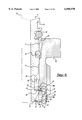
- FIG. 1 is an axial section of a first embodiment of a plug-in coupling in accordance with the invention, whereby the completely inserted full lock-in position is drawn in the left half of the figure and the partially inserted pre-lock position, for the case of the locked position for releasing the lock-in connection respectively, is in the right half.
- FIG. 2 is an axial section of the individual stages of the course of assembly of the first embodiment of a plug-in coupling in accordance with the invention illustrated in FIG. 1, presented according to time in the sequence 2a through 2f, at a smaller scale;
- FIG. 3 likewise is an axial section of the individual stages of the course of assembly of a second embodiment of a plug-in coupling in accordance with the invention, presented according to time in the sequence 3a through 3d;
- FIG. 4 is an axial section of the two stages of the course of disassembly of the second embodiment of a plug-in coupling in accordance with the invention illustrated in FIG. 3 presented according to time in the sequence 4a, 4b;
- FIG. 5 is an axial section of a third embodiment of a plug-in coupling in accordance with the invention at full lock-in, first in an unlocked position for disengaging the lock-in connection (FIG. 5a), and secondly in a locked position (FIG. 5b);
- FIG. 6 is an enlarged axial section of a fourth embodiment of a plug-in coupling in accordance with the invention.
- FIG. 7 is an axial section of two advantageous alternative embodiments (FIGS. 7a, 7b) of the holding element of the fourth embodiment of the plug-in coupling in accordance with the invention of FIG. 6, in the area of detail VII.
- a first embodiment of a plug-in coupling in accordance with the invention consists of two coupling components, namely a receiving component 2 and a connector component 4.
- the connector component 4 With a connecting shaft 6, the connector component 4 can be inserted into a locating opening 8 of the receiving component 2, thereby being sealed against the locating opening 8 by at least one gasket 10, and it is also arrestable, secured against disengagement opposite the direction of insertion (direction of arrow 14).
- both a partially inserted pre-lock position, shown on the right side of FIG. 1 and a completely inserted full lock-in position, shown as the left side of FIG. 1, of the connector component 4 are possible.
- a second seal 18, for sealing against the penetration of dirt, dust, humidity, and the like, can be provided, in the locating opening's 8 mouth area in particular, besides the gasket 10.
- the plug-in coupling has a holding element 20, which, as illustrated, is situated in a recess 22 of a coupling component, preferably receiving component 2, and, as illustrated, engages behind a locking edge 24 of the other coupling component, preferably the connector component 4, locking with positive fit in the pre-lock position and in the full lock-in position, respectively.
- the recess 22 is formed by an inner ring groove within the locating opening 8, while the locking edge 24 forms a one-sided limit stop of an outer ring groove on the connecting shaft 6.
- the holding element 20 is designed in such a way that it cooperates with the same single locking edge 24, both in the pre-lock position (FIG. 1, right side) and in the full lock-in position (FIG. 1, left side), respectively.
- the holding element 20 consists of a cage-like bracket 26 and two arresting elements 28, 30, which are axially one behind the other and clamped radial-elastically deformable in the bracket 26 in such a way, that, the locking edge 24 is engaged by the first arresting element 28 in the pre-lock position of FIG. 1, right side, and by the second arresting element 30 in the full lock-in position of FIG. 1, left side.
- the bracket 26 is preferably situated within the recess 22, designed as an inner ring groove, in the locating opening 8.
- the bracket 26 is preferably designed as a circular body with two retaining spaces 32 for the arresting elements 28, 30. As illustrated, the retaining spaces 32 can be designed as transverse groove-like recesses or even as inner ring grooves.
- the bracket 26 can be made as a single structural part, out of plastic in particular, or also as several parts.
- the arresting elements 28, 30 and the retaining spaces 32 receiving them can be designed in such a way, that the arresting elements 28, 30 can be pushed into the retaining spaces 32 perpendicular to the centerline of the bracket 26 from outside.
- arresting elements 28, 30 consist of plastic or metal, especially spring steel, and they can be designed as slotted spring lock washers or as spring clips with two spring arms, as stampings or out of spring wire for example, connected as one by a fastening section.
- the holding element 20 is designed and arranged relatively movable in the recess 22 of a coupling component 2 in such a way, that at least in the full lock-in position, FIG. 1, left side, (in the embodiments illustrated here this is advantageous both in the pre-lock position and in the full lock-in position) the holding element (20) and hence the arresting elements 28, 30, can be shifted from an unlocked position to a locked position by moving the holding element 20 opposite the direction of insertion 14.
- the lock-in connection 28, 24 or 30, 24 respectively can be released by radial movement of the arresting elements 28, 30.
- FIG. 1 shows each of the lock-in connections 28, 24 and 30, 24 with the holding element 20 in the locked position.
- two interconnecting sections 33a, 33b are provided which are arranged stationary to the recess 22 and cooperate with the arresting elements 28, 30.
- the bracket 26 has in particular, arranged diametrically opposite at least on the side radially facing the locking edge 24, two slot-like openings, arranged diametrically opposite each other, which, as a result of a radial motion of the arresting elements 28, 30 directed inwards, can be locally penetrated by the arresting elements 28, 30 for engaging behind the locking edge 24.
- the outwardly directed backward movement of the arresting elements 28, 30 in the locked position of the holding element 20 is restricted by the latching section 33a, 33b, respectively.
- sections 33a, 33b being components of the receiving component 2, in which the recess 22 is located.
- the latching sections 33a, 33b are sections mutually staggered axially in the recess 22, each with a diameter reduced in comparison with the maximum diameter of the recess 22.
- FIG. 2a shows the first stage, in which the connector component 4 is already inserted into the locating opening 8 of the receiving component 2. Seen in the direction of insertion 14, the holding element 20 is on the front edge 34 of the recess 22. The two arresting elements 28, 30 project into the locating opening 8. A conically designed point 36 of the connector component 4 thereby becomes arranged on the first arresting element 28. The backward movement of the arresting element 28, which is directed radially outwards (occurring from widening), is blocked in this position, since the retaining space 32 for the arresting element 28 is in the region of the first latching section 33a.
- the holding element 20 is carried along by the connector component's 4 point 36 during farther insertion of the connector component 4, until the retaining space 32 is in the region 38, adjacent to the first latching section 33a in the direction of insertion 14, of a larger diameter of the recess 22.
- a projection 40, directed radially outwards, of the bracket 26 becomes arranged on a projection of recess 22, which is also directed radially inwards and is formed by the second latching section 33b. This produces resistance against farther movement of the holding element 20 in the connector component's 4 direction of insertion 14.
- FIG. 2d shows the attainment of the partially inserted, incompletely sealed prelock position, in which the first arresting element 28 engages behind the locking edge 24 of the connector component 4.
- the arresting element 28 is still in an unlocked position, in which the lock-in connection 28, 24 can still be released.
- the stage of assembly illustrated in the right side of FIG. 1, can follow the stage of FIG. 2d.
- the arresting element 28 arrives in a locked position by a shifting of the holding element 20 from a backwards movement of the connector component 4.
- the backward movement of the connector component 4 can be produced by simply pulling back or (as a rule) by pressurization.
- the plug-in coupling in accordance with the invention does not arrive in the stage illustrated in FIG. 1, right side, but in a stage in accordance with FIG. 2e.
- a radial movement of the second arresting element 30 outwards occurs when the holding element 20 stays fixed.
- the retaining space 32 for the arresting element 30 is then in a position lying behind the second latching section 33b in the direction of insertion 14. Its opening, directed radially outwards, lies in a second region 42 of a larger diameter of the recess 22. In this stage, significant mating forces appear for the first time because of the pressing of the gaskets 10, 18.
- FIG. 2f now shows attainment of the completely inserted, completely pressure-tight sealed full lock-in position, in which the locking edge 24 of the connector component 4 is now engaged from behind by the second arresting element 30, which is itself now in its unlocked position, just like the first arresting element 28.
- the second limit stop of the outer ring groove on the connecting shaft 6, opposite the locking edge 24, is a conical sloped surface 44 designed similar to the connector's point 36. Under the effect of the radial forces directed outwards, caused by the arrangement of the first arresting element 28 on the conically designed sloped surface 44 of the connector component 4, a radial movement outwards occurs in the recess's 22 first region of enlarged diameter 38 during insertion, to prevent damage due to over-assembly (insertion too deep).
- FIG. 1 The state of the completely and orderly assembled plug-in coupling in accordance with the invention, (FIG. 1, left side), follows the stage illustrated in FIG. 2f.
- the second arresting element 30 has arrived at its locked position from its unlocked position through a shifting of the holding element 20 opposite the direction of insertion 14.
- a backward movement of the arresting element 30 directed radially outwards is prevented or restricted by the latching section 33b.
- the backward movement mainly occurs by the spring action of the gasket 18 in the locating opening's 8 mouth area.
- a high operational dependability of the plug-in connector is given by the locking of the connector component 4 with the receiving component 2, attained with the help of the holding element 20, and the subsequent latching of the arresting elements 28, 30.
- the receiving component 2 consists of at least two detachable parts connected together, namely a base part 50 and an insert 52, whereby these parts 50, 52 between each other delimit the recess 22 receiving the holding element 20.
- the connecting shaft 6 can be extracted together with the insert 52 after the insert 52 has been released by the base part 50.
- the first region 38 of the recess's 22 enlarged diameter opposite the first latching section 33a is located in the insert 52
- the second region 42 of the recess's 22 enlarged diameter opposite the second latching section 33b is advantageously located in the base part 50.
- FIGS. 3 The second example of a plug-in coupling in accordance with the invention is described in FIGS. 3 (assembly--FIGS. 3a through 3d) and 4 (disassembly FIGS. 4a and 4b).
- the characteristic feature of the second example consists of the second latching section 33b being a component of a separate latching part 54, which can be designed of a ring part consisting of plastic.
- the region 38 of larger diameter, which borders the region of the first latching section 33a in the direction of insertion 14, is also in the latching part 54.
- the latching part 54 can be fastened to the coupling component having the recess 22, on insert 52 of the receiving component 2 in particular, by a detachable connection.
- An advantage of this embodiment is that the insert 52 is easier to manufacture because of the simpler form of the part of the recess 22 inside it.
- FIG. 3a shows the insert 52 of the receiving component 2, the separate latching part 54, which can be fastened to it, and the holding element 20 before the insertion of the connector component 4.
- the insert 52 and the latching part 54 preferably have complementary arresting agents, namely an outer torus 56 on the insert 52 and an inner torus 58 on the latching part 54, for producing their detachable connection.
- the holding element 20 is partially engaged around its perimeter by the insert 52 and partially by the latching part 54.
- FIG. 3b shows the stage of incomplete assembly of the plug-in coupling's second embodiment in accordance with the invention.
- the insert 52 and latching part 54 are locked together by the outer torus 56 on the insert 52 and an inner torus 58 on the latching part 54.
- This is the pre-lock position of the connector component 4, and the first arresting element 28 has arrived at a locked position by shifting the holding element opposite the direction of insertion 14, produced by a premature pressurization for example.
- the first latching section 33a causing the locking is formed by an end segment of the insert 52 on the end facing the base part 50.
- the second arresting element 30 has also arrived at a locked position in which the motion directed radially outwards is prevented by the second latching section 33b.
- the second latching section 33b is thereby formed by a region of the separate latching part 54 which is reduced compared to the maximum inner diameter.
- the completely inserted, completely pressure-tight sealed full lock-in position is achieved in accordance with FIG. 3c.
- the second arresting element 30 engages behind the connector component's 4 locking edge 24, after the connector's point 36 with the locking edge 24 was led past it. In this stage, both the first arresting element 28 and the second arresting element 30 are in an unlocked position.
- the projection 40 of the holding element 20 (or of its bracket 26), directed radially outwards, fits a projection of the latching part 54 which is directed radially inwards and which is also formed here by the second latching section 33b.
- FIG. 3d shows the achievement of the final assembly state, i.e. there is a complete and orderly assembled plug-in coupling in accordance with the invention. From the stage of assembly in FIG. 3c, both arresting elements 28, 30 have arrived at their respective locked positions from their unlocked positions by a shifting of the holding element 20 against the direction of insertion 14.
- the second embodiment of the plug-in coupling in accordance with the invention has an improved ability to disengage which is advantageous for assembly, in contrast to the first embodiment.
- the insert 52 is first released from the base part 50.
- the connecting shaft 6 can be extracted together with the insert 52.
- FIG. 4a shows that the connection 56, 58 between the latching part 54 and the insert 52 can also be separated in a simple way. This occurs by pulling the latching part 54 off the insert in the direction of insertion 14.
- the connecting shaft 6 can be shoved out farther in the direction of insertion 14 into the position illustrated in FIG. 4b, in which the holding element 20 with both of its arresting elements 28, 30 is completely exposed. Both arresting elements 28, 30 can be removed, whereby a device to aid assembly can be used for propping open, for example.
- FIG. 5 illustrates a third embodiment of a plug-in coupling in accordance with the invention, where FIG. 5a shows the stage of assembly immediately after the full lock-in position and FIG. 5b the stage after the full lock-in and appearance of the locked position.
- the characteristic feature of the third example is that, as in the second embodiment, the second latching section 33b is a component of a second latching part 54, which can likewise be designed as a ring part, but the latching part 54 cannot be connected with the receiving component 2. In the assembled state, the latching part 54 is merely held in the receiving component 2 between the two parts (base part 50 and insert 52) which border the recess 22 and which are detachably connected with each other.
- the projection directed radially inwards (labeled as 62 here) of the latching part 54, on which the outwardly directed projection 40 of the holding element 20 (or its bracket 26) becomes arranged, is not formed by the second latching segment 33b here, but, in the direction of insertion 14, comes before the latching section 33b and also protrudes inwards opposite it.
- the cross section of the latching part's 54 wall thus receives the shape of an open U radially outwards.
- the projection 62 which cooperates with the holding element's 20 projection 40 is on the U's lower connecting arc, and extensions, each directed axially outward from the U's sides toward a front-sided arrangement on the base part 50 and on the insert 52 of the receiving component 2, are on its side ends.
- the holding element's projection 40 directed radially outwards is accomplished as a one-sided limit stop of an outer ring groove on the bracket 26, lying between the retaining spaces 32 for the arresting elements 28, 30, whereby the axially directed movement of the latching part's 54 projection 62 directed radially inwards is restricted by this groove in both axial directions. Additionally, latching part 54 and bracket 26 can be so formed, that the latching part 54 can be latched onto the holding element 20.
- a separate latching part 54 which can be inserted as a loose ring between the base part 50 and the insert 52, is likewise provided.
- the holding element 20 has a shape that is shortened in length compared to the remaining embodiments, so that it isn't held in a region of expanded diameter of the insert's 52 locating opening 8, as in the other embodiments, but is held completely behind the insert 52, as seen from the direction of insertion 14, in the recess 22.
- Both latching sections 33a, 33b are components of the latching part 54.
- the cross section of the latching element's 54 wall has the shape of a lying F, which faces the direction of insertion 14 with the foot of its vertical girder aligned with the plug-in coupling's axis, and faces inwards with its horizontal radially directed girders.
- the latching sections 33a, 33b are on the fronts of the two horizontal girders of the F, whereby the second latching section 33b has a small recess 64, whose edge forms the projection which cooperates with the holding element's 20 projection 40.
- the latching part 54 fits the locating opening 8 on the inner wall of the insert 52 with its upper F-girder, and the front of the base part 50 with the foot of its vertical girder.
- the holding element 20 can be shaped in a different way in this fourth embodiment in accordance with the invention.
- the alternative embodiments concern the shape of the perimeter of an end section 66 of the holding element 20 on its side facing the direction of insertion 14.
- FIG. 7a additionally shows an embodiment in which this end section 66 has a diameter step 68 on the perimeter, which is provided to facilitate the insertion with a chamfer 70 which diminishes conically in the direction of insertion 14, and
- FIG. 7b shows an embodiment with a collar-like shape of the perimeter in the end segment 66.
- a ring channel 72 which is open in the direction of insertion 14 but closed opposite the direction of insertion 14, is formed around the base of the holding element 20 by the collar-like shape (FIG. 7b).
- the pressure medium can act against the direction of insertion in this ring channel 72 and thus support the backward movement of the holding element 20.
- the collar 74 is provided with a piloting slant 76, similar to the chamfer 70 which diminishes conically in the direction of insertion 14 of the embodiment in accordance with FIG. 7a.
- a backwards bearing surface 78 for the latching section 54 is present.
- the holding element 20 and latching part 54 can be fit to each other in such a way that the second horizontal girder of the F carrying the latching section 33b has a recess (shown in FIG. 6 but not labeled) and the collar 74 has an external shape complementary to this recess.
- the holding element 20 and the latching part 54 are effectively secured against relative movement from pressurization in the locked position.
- the fourth embodiment combines the advantages of high dependability, simple assembly and disassembly, and the opportunity of using standard parts as components of receiving component 2.
- the invention is not limited to the examples illustrated and described, but also includes all embodiments which work with the same idea of the invention.
- the invention is moreover not limited to the combination of characteristics defined in claim 1, but can also be defined by any desired other combination of particular characteristics of all the disclosed individual characteristics as a whole. This means in principle, that practically every individual characteristic of claim 1 can be left out and replaced by at least one individual characteristic disclosed at another place in the application. In this respect, claim 1 is to be understood merely as an initial attempt at formulation for the invention.
Landscapes
- Engineering & Computer Science (AREA)
- General Engineering & Computer Science (AREA)
- Mechanical Engineering (AREA)
- Transportation (AREA)
- Quick-Acting Or Multi-Walled Pipe Joints (AREA)
- Earth Drilling (AREA)
Priority Applications (1)
| Application Number | Priority Date | Filing Date | Title |
|---|---|---|---|
| US09/872,984 US6685790B2 (en) | 1998-04-29 | 2001-06-01 | Advertising placard |
Applications Claiming Priority (2)
| Application Number | Priority Date | Filing Date | Title |
|---|---|---|---|
| DE29719247U DE29719247U1 (de) | 1997-10-29 | 1997-10-29 | Steckkupplung für Druckmittelsysteme |
| DE29719247 | 1997-10-29 |
Related Child Applications (1)
| Application Number | Title | Priority Date | Filing Date |
|---|---|---|---|
| US09/657,372 Continuation US6241187B1 (en) | 1998-04-29 | 2000-09-08 | Advertising placard |
Publications (1)
| Publication Number | Publication Date |
|---|---|
| US6095570A true US6095570A (en) | 2000-08-01 |
Family
ID=8047923
Family Applications (1)
| Application Number | Title | Priority Date | Filing Date |
|---|---|---|---|
| US09/069,441 Expired - Lifetime US6095570A (en) | 1997-10-29 | 1998-04-29 | Plug-in coupling for pressure application systems |
Country Status (4)
| Country | Link |
|---|---|
| US (1) | US6095570A (de) |
| EP (1) | EP0913618B1 (de) |
| BR (1) | BR9801505A (de) |
| DE (2) | DE29719247U1 (de) |
Cited By (22)
| Publication number | Priority date | Publication date | Assignee | Title |
|---|---|---|---|---|
| US6412828B1 (en) * | 1998-12-03 | 2002-07-02 | Staubli Faverges | Quick safety connection for removably joining pipes |
| WO2003042591A1 (en) * | 2001-11-15 | 2003-05-22 | Volvo Lastvagnar Ab | A coupling device for pressure fluid conduits and a method for the manufacturing of such a coupling, comprising a leakage groove for indication of leakage |
| US20040056484A1 (en) * | 2001-02-19 | 2004-03-25 | Oh-Kyung Kwon | Tube coupler |
| US7014215B2 (en) * | 2001-03-09 | 2006-03-21 | The Gates Corporation | Quick connect coupling |
| WO2006049959A1 (en) * | 2004-10-29 | 2006-05-11 | The Gates Corporation | Quick connect coupling |
| US20070249197A1 (en) * | 2006-04-03 | 2007-10-25 | Martin Spranger | Coupling for tubular elements |
| EP2159466A3 (de) * | 2008-08-27 | 2010-06-02 | Johannes Schäfer vormals Stettiner Schraubenwerke GmbH & Co. KG | Steckverbindung für Rohrleitungen |
| US20100133811A1 (en) * | 2006-11-25 | 2010-06-03 | Balltec Limited | Connector |
| CN101998900A (zh) * | 2008-04-12 | 2011-03-30 | 福士汽车配套部件责任有限公司 | 制造具有环形横截面的成型件的方法及根据该方法制造的成型件 |
| KR20120024748A (ko) * | 2009-05-11 | 2012-03-14 | 히타치 긴조쿠 가부시키가이샤 | 관 조인트 |
| US9869416B2 (en) * | 2016-01-26 | 2018-01-16 | Tectran Mfg. Inc. | Swivel coupling and hose assemblies and kits utilizing the same |
| US10473243B2 (en) * | 2016-01-26 | 2019-11-12 | Tectran Mfg. Inc. | Hose repair kit with live swivel coupling |
| US10788149B2 (en) * | 2015-11-24 | 2020-09-29 | Self Energising Coupling Company Limited | Fluid coupling |
| US20210071793A1 (en) * | 2018-04-24 | 2021-03-11 | Reliance Worldwide Corporation | Fluid connector |
| US10969041B2 (en) * | 2018-10-01 | 2021-04-06 | Hyundai Motor Company | Connector for pneumatic circuit |
| US11384880B2 (en) * | 2019-05-07 | 2022-07-12 | A. Raymond Et Cie | Quick connect assembly with verification tab |
| US11421807B2 (en) | 2018-07-23 | 2022-08-23 | Deere & Company | Universal threadless connection |
| WO2024200494A1 (fr) | 2023-03-27 | 2024-10-03 | A. Raymond Et Cie | Élément femelle d'un dispositif de raccordement fluidique et dispositif de raccordement fluidique comprenant un tel élément |
| USD1079903S1 (en) | 2018-08-14 | 2025-06-17 | Reliance Worldwide Corporation | Tubular connector |
| US12338928B2 (en) | 2018-08-14 | 2025-06-24 | Reliance Worldwide Corporation | Plumbing fitting |
| US12345361B2 (en) | 2018-08-14 | 2025-07-01 | Reliance Worldwide Corporation | Plumbing fitting |
| US12553555B2 (en) | 2018-08-14 | 2026-02-17 | Reliance Worldwide Corporation | Device and method for assembling components of a plumbing fitting |
Families Citing this family (14)
| Publication number | Priority date | Publication date | Assignee | Title |
|---|---|---|---|---|
| DE19848489B4 (de) * | 1998-10-21 | 2006-01-26 | Johannes Schäfer vorm. Stettiner Schraubenwerke GmbH & Co. KG | Lösbare Steckverbindung für den Anschluß von Rohrleitungen |
| EP1033520B2 (de) † | 1999-03-04 | 2010-05-26 | Johannes Schäfer vormals Stettiner Schraubenwerke GmbH & Co. KG | Lösbare Steckverbindung für den Anschluss von Rohrleitungen |
| DE20214631U1 (de) | 2002-09-20 | 2004-02-19 | Voss Automotive Gmbh | Adapter-Zwischenring für ein Einschraubteil eines Fluid-Stecksystems |
| DE202007012584U1 (de) | 2007-04-02 | 2008-08-14 | Voss Automotive Gmbh | Anschlusselement für Medienleitungen sowie Spritzform-Vorrichtung zum Herstellen des Anschlusselementes |
| DE202007012104U1 (de) | 2007-08-29 | 2009-01-08 | Voss Automotive Gmbh | Steckverbindung für Druckmittelsysteme |
| EP2283268B1 (de) | 2008-07-14 | 2012-05-09 | Voss Automotive GmbH | Steckkupplung für druckmittel-leitungen |
| DE202008009398U1 (de) | 2008-07-14 | 2009-11-19 | Voss Automotive Gmbh | Steckkupplung für Druckmittel-Leitungen |
| DE202008009399U1 (de) | 2008-07-14 | 2009-11-19 | Voss Automotive Gmbh | Steckkupplung für Druckmittel-Leitungen |
| DE102011056601A1 (de) | 2011-12-19 | 2013-06-20 | Voss Automotive Gmbh | Hohlzylindrisches Schraubteil und Verfahren zu seiner Herstellung |
| DE102013006395A1 (de) | 2013-04-12 | 2014-10-16 | Wabco Gmbh | Anschlussstück zur druckdichten Anbindung eines Leitungsendes an ein Aufnahmegehäuse |
| DE102022120888A1 (de) | 2022-08-18 | 2024-02-29 | Voss Automotive Gmbh | "Steckkupplung mit Leckageindikator für Fluidleitungen" |
| DE102024117912A1 (de) | 2024-06-25 | 2026-01-08 | Voss Automotive Gmbh | Verfahren zur Herstellung eines hohlzylindrischen Formteils mit Gewinde |
| WO2026003124A1 (de) | 2024-06-25 | 2026-01-02 | Voss Automotive Gmbh | Hohlzylindrisches formteil mit gewinde |
| DE102024117914A1 (de) | 2024-06-25 | 2026-01-08 | Voss Automotive Gmbh | Hohlzylindrisches Formteil mit Gewinde |
Citations (7)
| Publication number | Priority date | Publication date | Assignee | Title |
|---|---|---|---|---|
| US3986730A (en) * | 1973-12-21 | 1976-10-19 | Martelli Louis P | Pipe fittings |
| US4105226A (en) * | 1976-06-01 | 1978-08-08 | Celanese Corporation | Snap-in fittings and coupling ring therefor |
| US4126335A (en) * | 1975-10-23 | 1978-11-21 | Armaturenfabrik Hermann Voss | Hose and pipe coupling |
| US4471978A (en) * | 1978-06-07 | 1984-09-18 | Dieter Kramer | Push-pull connecting system for pressure lines, brake-system lines in particular |
| US5112089A (en) * | 1987-02-03 | 1992-05-12 | Automobiles Peugeot | Rapid assembly connector |
| DE19621535A1 (de) * | 1996-05-29 | 1997-12-04 | Voss Armaturen | Steckkupplung für Druckmittelsysteme |
| US5845944A (en) * | 1995-10-03 | 1998-12-08 | Raufoss Technology A/S | Coupling for pressurized medium |
Family Cites Families (2)
| Publication number | Priority date | Publication date | Assignee | Title |
|---|---|---|---|---|
| DE19522052A1 (de) * | 1995-06-17 | 1996-12-19 | Voss Armaturen | Steckkupplung für Druckmittelsysteme |
| DE19536333A1 (de) * | 1995-09-29 | 1997-04-03 | Voss Armaturen | Steckkupplung für Druckmittelsysteme |
-
1997
- 1997-10-29 DE DE29719247U patent/DE29719247U1/de not_active Expired - Lifetime
-
1998
- 1998-04-29 US US09/069,441 patent/US6095570A/en not_active Expired - Lifetime
- 1998-04-29 BR BR9801505-2A patent/BR9801505A/pt not_active IP Right Cessation
- 1998-06-30 DE DE59806037T patent/DE59806037D1/de not_active Expired - Lifetime
- 1998-06-30 EP EP98112025A patent/EP0913618B1/de not_active Expired - Lifetime
Patent Citations (7)
| Publication number | Priority date | Publication date | Assignee | Title |
|---|---|---|---|---|
| US3986730A (en) * | 1973-12-21 | 1976-10-19 | Martelli Louis P | Pipe fittings |
| US4126335A (en) * | 1975-10-23 | 1978-11-21 | Armaturenfabrik Hermann Voss | Hose and pipe coupling |
| US4105226A (en) * | 1976-06-01 | 1978-08-08 | Celanese Corporation | Snap-in fittings and coupling ring therefor |
| US4471978A (en) * | 1978-06-07 | 1984-09-18 | Dieter Kramer | Push-pull connecting system for pressure lines, brake-system lines in particular |
| US5112089A (en) * | 1987-02-03 | 1992-05-12 | Automobiles Peugeot | Rapid assembly connector |
| US5845944A (en) * | 1995-10-03 | 1998-12-08 | Raufoss Technology A/S | Coupling for pressurized medium |
| DE19621535A1 (de) * | 1996-05-29 | 1997-12-04 | Voss Armaturen | Steckkupplung für Druckmittelsysteme |
Cited By (43)
| Publication number | Priority date | Publication date | Assignee | Title |
|---|---|---|---|---|
| US6412828B1 (en) * | 1998-12-03 | 2002-07-02 | Staubli Faverges | Quick safety connection for removably joining pipes |
| US20040056484A1 (en) * | 2001-02-19 | 2004-03-25 | Oh-Kyung Kwon | Tube coupler |
| US6869108B2 (en) * | 2001-02-19 | 2005-03-22 | Jinbo Precision Ind. Co., Ltd. | Tube coupler |
| US7014215B2 (en) * | 2001-03-09 | 2006-03-21 | The Gates Corporation | Quick connect coupling |
| US9039045B2 (en) | 2001-03-09 | 2015-05-26 | Gates Corporation | Quick connect coupling |
| US20060175834A1 (en) * | 2001-03-09 | 2006-08-10 | Cooper Adrian R | Quick connect coupling |
| US7150473B2 (en) * | 2001-11-15 | 2006-12-19 | Volvo Lastvagnar Ab | Coupling device comprising a leakage groove |
| WO2003042591A1 (en) * | 2001-11-15 | 2003-05-22 | Volvo Lastvagnar Ab | A coupling device for pressure fluid conduits and a method for the manufacturing of such a coupling, comprising a leakage groove for indication of leakage |
| US20050017504A1 (en) * | 2001-11-15 | 2005-01-27 | Volvo Lastvagnar | Coupling device for pressure fluid conduits and a method for the manufacturing of such a coupling, comprising a leakage groove for indication of leakage |
| US20080174111A1 (en) * | 2004-10-29 | 2008-07-24 | Mcgee Stephen | Quick connect coupling |
| CN101048614B (zh) * | 2004-10-29 | 2010-06-16 | 盖茨公司 | 快速连接接头和将快速连接接头的外连接部分插入到其端口中的方法 |
| US7364207B2 (en) | 2004-10-29 | 2008-04-29 | The Gates Corporation | Quick connect coupling |
| US20060108793A1 (en) * | 2004-10-29 | 2006-05-25 | Mcgee Stephen | Quick connect coupling |
| RU2344333C1 (ru) * | 2004-10-29 | 2009-01-20 | Дзе Гейтс Корпорейшн | Быстросоединяемое соединение |
| US7631905B2 (en) * | 2004-10-29 | 2009-12-15 | The Gates Corporation | quick connect coupling |
| WO2006049959A1 (en) * | 2004-10-29 | 2006-05-11 | The Gates Corporation | Quick connect coupling |
| US20070249197A1 (en) * | 2006-04-03 | 2007-10-25 | Martin Spranger | Coupling for tubular elements |
| US20100133811A1 (en) * | 2006-11-25 | 2010-06-03 | Balltec Limited | Connector |
| US8931807B2 (en) * | 2006-11-25 | 2015-01-13 | Balltec Limited | Connector |
| CN101998900A (zh) * | 2008-04-12 | 2011-03-30 | 福士汽车配套部件责任有限公司 | 制造具有环形横截面的成型件的方法及根据该方法制造的成型件 |
| US20110150602A1 (en) * | 2008-04-12 | 2011-06-23 | Sieper Guenter | Method for producing a moulded part with an annular cross-section and moulded part produced according to a method of this type |
| CN101998900B (zh) * | 2008-04-12 | 2015-06-03 | 福士汽车配套部件责任有限公司 | 制造具有环形横截面的成型件的方法及根据该方法制造的成型件 |
| US9023260B2 (en) * | 2008-04-12 | 2015-05-05 | Voss Automotive Gmbh | Method for producing a screw part with an annular cross-section |
| EP2159466A3 (de) * | 2008-08-27 | 2010-06-02 | Johannes Schäfer vormals Stettiner Schraubenwerke GmbH & Co. KG | Steckverbindung für Rohrleitungen |
| KR20120024748A (ko) * | 2009-05-11 | 2012-03-14 | 히타치 긴조쿠 가부시키가이샤 | 관 조인트 |
| US9182061B2 (en) * | 2009-05-11 | 2015-11-10 | Hitachi Metals, Ltd. | Pipe joint |
| EP2431645A4 (de) * | 2009-05-11 | 2017-05-03 | Hitachi Metals, Ltd. | Rohrverbindung |
| US20120068454A1 (en) * | 2009-05-11 | 2012-03-22 | Hitachi Metals Ltd. | Pipe joint |
| US10788149B2 (en) * | 2015-11-24 | 2020-09-29 | Self Energising Coupling Company Limited | Fluid coupling |
| US10857989B2 (en) * | 2016-01-26 | 2020-12-08 | Tectran Mfg. Inc. | Swivel coupling and hose assemblies and kits utilizing the same |
| US10473243B2 (en) * | 2016-01-26 | 2019-11-12 | Tectran Mfg. Inc. | Hose repair kit with live swivel coupling |
| US9869416B2 (en) * | 2016-01-26 | 2018-01-16 | Tectran Mfg. Inc. | Swivel coupling and hose assemblies and kits utilizing the same |
| US20210071793A1 (en) * | 2018-04-24 | 2021-03-11 | Reliance Worldwide Corporation | Fluid connector |
| US11802643B2 (en) * | 2018-04-24 | 2023-10-31 | Reliance Worldwide Corporation | Fluid connector |
| US11421807B2 (en) | 2018-07-23 | 2022-08-23 | Deere & Company | Universal threadless connection |
| USD1079903S1 (en) | 2018-08-14 | 2025-06-17 | Reliance Worldwide Corporation | Tubular connector |
| US12553555B2 (en) | 2018-08-14 | 2026-02-17 | Reliance Worldwide Corporation | Device and method for assembling components of a plumbing fitting |
| US12345361B2 (en) | 2018-08-14 | 2025-07-01 | Reliance Worldwide Corporation | Plumbing fitting |
| US12338928B2 (en) | 2018-08-14 | 2025-06-24 | Reliance Worldwide Corporation | Plumbing fitting |
| US10969041B2 (en) * | 2018-10-01 | 2021-04-06 | Hyundai Motor Company | Connector for pneumatic circuit |
| US11384880B2 (en) * | 2019-05-07 | 2022-07-12 | A. Raymond Et Cie | Quick connect assembly with verification tab |
| FR3147345A1 (fr) | 2023-03-27 | 2024-10-04 | A. Raymond Et Cie | Élément femelle d’un dispositif de raccordement fluidique et dispositif de raccordement fluidique comprenant un tel élément |
| WO2024200494A1 (fr) | 2023-03-27 | 2024-10-03 | A. Raymond Et Cie | Élément femelle d'un dispositif de raccordement fluidique et dispositif de raccordement fluidique comprenant un tel élément |
Also Published As
| Publication number | Publication date |
|---|---|
| EP0913618B1 (de) | 2002-10-23 |
| DE59806037D1 (de) | 2002-11-28 |
| EP0913618A1 (de) | 1999-05-06 |
| DE29719247U1 (de) | 1999-02-25 |
| BR9801505A (pt) | 1999-09-28 |
Similar Documents
| Publication | Publication Date | Title |
|---|---|---|
| US6095570A (en) | Plug-in coupling for pressure application systems | |
| JP3510269B2 (ja) | 加圧媒体の継ぎ手 | |
| US5002315A (en) | Quick connector | |
| CN1322263C (zh) | 可转动的快速连接器 | |
| US3479068A (en) | Permanently coupled assemblies | |
| US5553895A (en) | Coupling assembly | |
| US4943091A (en) | Quick connector | |
| US5002254A (en) | Automatic coupler for pressurized fluid circuit | |
| US6921113B1 (en) | Connector assembly and method of manufacture | |
| US5707085A (en) | Fluid coupling | |
| JP4560781B2 (ja) | 傾斜部の輪郭を改良したカップリングアセンブリ | |
| JP3674390B2 (ja) | クィックコネクターカップリング及び雌ハウジング | |
| CA2166744A1 (en) | Fluid quick connector | |
| CA2310179A1 (en) | Coupling assemblies for providing fluid connection | |
| US6027144A (en) | Plug-in connector for pressure medium systems | |
| CN109477604A (zh) | 连接器 | |
| US4487437A (en) | Threadless connector | |
| JP2003247686A (ja) | 油圧ダクトを接続する管継手 | |
| US6082399A (en) | Quick coupling for hoses or pipes for pressure media | |
| US4660866A (en) | Restrained pipe joint | |
| KR101001229B1 (ko) | 파이프용 신속 작동 커플링 | |
| JP2002031285A (ja) | パイプと剛性要素との迅速連結装置 | |
| CA1204128A (en) | Coupling for connecting hose or pipe ends | |
| JP2000320772A (ja) | 流体継手 | |
| JPH0823397B2 (ja) | 離脱防止管継手 |
Legal Events
| Date | Code | Title | Description |
|---|---|---|---|
| AS | Assignment |
Owner name: ARMATURENFABRIK HERMANN VOSS GMBH & CO., GERMANY Free format text: ASSIGNMENT OF ASSIGNORS INTEREST;ASSIGNORS:HAGEN, HARALD;KAMINISKI, VOLKER;BERG, MANFRED;AND OTHERS;REEL/FRAME:009288/0500;SIGNING DATES FROM 19980518 TO 19980525 |
|
| STCF | Information on status: patent grant |
Free format text: PATENTED CASE |
|
| CC | Certificate of correction | ||
| FPAY | Fee payment |
Year of fee payment: 4 |
|
| AS | Assignment |
Owner name: VOSS AUTOMOTIVE GMBH, GERMANY Free format text: CHANGE OF NAME;ASSIGNOR:ARMATURENFABRIK HERMANN VOSS GMBH + CO;REEL/FRAME:018645/0959 Effective date: 20011203 |
|
| FPAY | Fee payment |
Year of fee payment: 8 |
|
| FPAY | Fee payment |
Year of fee payment: 12 |
|
| SULP | Surcharge for late payment |
Year of fee payment: 11 |