US6121664A - Semiconductor memory device - Google Patents
Semiconductor memory device Download PDFInfo
- Publication number
- US6121664A US6121664A US08/811,785 US81178597A US6121664A US 6121664 A US6121664 A US 6121664A US 81178597 A US81178597 A US 81178597A US 6121664 A US6121664 A US 6121664A
- Authority
- US
- United States
- Prior art keywords
- transistors
- memory cells
- semiconductor substrate
- configuration
- grooves
- Prior art date
- Legal status (The legal status is an assumption and is not a legal conclusion. Google has not performed a legal analysis and makes no representation as to the accuracy of the status listed.)
- Expired - Fee Related
Links
Images


Classifications
-
- H—ELECTRICITY
- H10—SEMICONDUCTOR DEVICES; ELECTRIC SOLID-STATE DEVICES NOT OTHERWISE PROVIDED FOR
- H10B—ELECTRONIC MEMORY DEVICES
- H10B69/00—Erasable-and-programmable ROM [EPROM] devices not provided for in groups H10B41/00 - H10B63/00, e.g. ultraviolet erasable-and-programmable ROM [UVEPROM] devices
-
- H—ELECTRICITY
- H10—SEMICONDUCTOR DEVICES; ELECTRIC SOLID-STATE DEVICES NOT OTHERWISE PROVIDED FOR
- H10B—ELECTRONIC MEMORY DEVICES
- H10B20/00—Read-only memory [ROM] devices
-
- H—ELECTRICITY
- H10—SEMICONDUCTOR DEVICES; ELECTRIC SOLID-STATE DEVICES NOT OTHERWISE PROVIDED FOR
- H10B—ELECTRONIC MEMORY DEVICES
- H10B20/00—Read-only memory [ROM] devices
- H10B20/27—ROM only
- H10B20/30—ROM only having the source region and the drain region on the same level, e.g. lateral transistors
- H10B20/38—Doping programmed, e.g. mask ROM
Definitions
- the present invention relates to a semiconductor device and a method for producing the same.
- the present invention relates to a semiconductor device which has both NAND-type and NOR-type cell transistors as memory cell transistors (hereinafter, referred to as cell transistors) simultaneously present on a single semiconductor substrate, and to a method for producing the same.
- NAND-type ROM Conventionally known types of memory cells in a mask ROM are a NAND-type ROM and a NOR-type ROM.
- the NAND-type ROM has a plurality of columns of transistors, each column being made of a plurality of cell transistors connected in series. In each of the transistor columns, enhancement-type transistors and depletion-type transistors are arranged in accordance with ROM data so that the ROM data can be written.
- the NOR-type ROM has a plurality of columns of transistors, each including a plurality of cell transistors connected in parallel with respect to the bit line. In each of the transistor columns, threshold voltages are set above the power source voltage for the transistors selected in accordance with the ROM data so that the ROM data can be written.
- NAND-type ROMs are excellent in high integration but poor in high speed operation.
- NOR-type ROMs are excellent in high speed operation but poor in high integration.
- the reason why the NOR-type ROMs are poor in high integration is as follows.
- the NOR-type ROM generally requires one contact hole for wire connection for every two cell transistors. This makes it necessary to reserve both a region for contact hole formation and a margin for mask alignment during contact hole formation. Consequently, miniaturization of memory cells becomes difficult.
- NAND-type ROMs have mainly been used for the realization of high integration.
- the reason for this is that since a plurality of cell transistors are connected in series to configure a plurality of transistor columns, the contact holes need only to be formed at both ends of the transistor columns. The larger the number of transistors to be connected in series, the higher the integration becomes.
- One conventional example which is to meet such demand is a high integration NOR-type ROM (hereinafter referred to as the first conventional example) in which device isolation is achieved without forming an isolation wall, thereby reducing the step of the isolation wall, and the contact hole for wire connection is not formed for every memory cell. Therefore, advantages of both the NAND-type ROM and the NOR-type ROM are retained.
- a plurality of high concentration diffusion layers 202 and 203 which become source/drain regions and bit lines are formed in parallel in a memory cell formation region of a semiconductor substrate 201.
- a gate insulating film 204 Provided over this semiconductor substrate 201 with a gate insulating film 204 inserted therebetween are a plurality of gate electrodes (word lines) 205 which extend perpendicular to the high concentration diffusion layers 202 and 203 which become bit lines.
- Regions where the gate electrodes 205 or the high concentration diffusion layers 202 and 203 are not formed are ion-implanted with an impurity having conductivity type different from that of the source/drain regions 202. These regions 206 are designated by function as an isolation between the cell transistors.
- reference numerals 251 and 252 indicate the cell transistor region.
- the semiconductor substrate 201 Since memory cells having such a configuration do not have the isolation wall such as a LOCOS (local oxidation of silicon) film, the semiconductor substrate 201 has a planar surf ace. For this reason, the gate electrodes 205 can be disposed with a pitch which is less than the typical fabrication limit. Furthermore, since the isolation walls 206 can be self-aligningly ion-implanted using the gate electrodes 205 as a mask, high integration of the memory cells is greatly facilitated.
- LOCOS local oxidation of silicon
- Methods for further achieving higher integration in NAND-type ROMs or NOR-type ROM described above include a method where the gate electrodes have a multi-layer structure and a method where the isolation wall is not provided.
- FIGS. 55A, 55B and 55C illustrate the conventional example suggested in Japanese Laid-Open Patent Publication No. 53-41188.
- This conventional example was applied to a NAND-type ROM.
- a first gate oxide film 304 is formed on a semiconductor substrate 301, and then a plurality of first gate electrodes 305 are provided thereon in the horizontal direction with a separation of prescribed distance, thereby forming first MIS (metal insulator semiconductor)-type transistors.
- a second gate oxide film 306 is formed on the entire surface of the semiconductor substrate 301 so as to cover the first gate electrodes 305.
- second gate electrodes 307 are provided thereon, thereby forming second MIS-type transistors.
- the second gate electrodes 307 are provided between the first gate electrodes 305. Therefore, the occupied area for each cell transistor when viewed from above can be made one half of that in the above first conventional example. As a result, the degree of integration can be doubled.
- FIGS. 56A, 56B and 56C illustrate the conventional example suggested in Japanese Laid-Open Patent Publication No. 63-131568.
- This conventional example was applied to a NOR-type ROM.
- the source regions 402 and the drain regions 403 are formed on the semiconductor substrate 401 in parallel with a separation of a channel length, and then the gate electrodes 405 are formed so as to become perpendicular to the source regions 402, the drain regions 403 and the channel regions 404 formed between the source regions 402 and the channel regions 404.
- These gate electrodes are also provided in a plurality of numbers in the horizontal direction with a separation of a prescribed distance.
- Reference numeral 406 designates a gate insulating film. According to this conventional example, since isolation walls are not present between the gate electrodes 405, a pitch between lines can be reduced thereby and higher integration of memory cells can be achieved.
- a semiconductor memory device including: a semiconductor substrate; a plurality of first transistors formed over said semiconductor substrate in a matrix configuration, each of said first transistors having a channel region; a plurality of second transistors formed over said semiconductor substrate in a matrix configuration, each of said second transistors having a channel region; a plurality of word lines formed in parallel in a first direction, each of said word lines functioning as a word line and a gate electrode; wherein at least two channel regions of said plurality of first transistors make contact in a second direction substantially perpendicular with respect to said first direction; and at least two channel regions of said plurality of second transistors make contact in said second direction.
- said plurality of first transistors are classified into a first group of transistors having a first threshold voltage for making said first transistor conductive and a second group of transistors having a second threshold voltage for making said first transistor conductive;
- said plurality of second transistors are classified into a third group of transistors having a third threshold voltage for making said second transistor conductive and a fourth group of transistors having a fourth threshold voltage for making said second transistor conductive.
- the semiconductor memory device includes: a semiconductor substrate; a plurality of word lines formed over said semiconductor substrate in parallel in a first direction; a column of transistors including a plurality of first transistors, each of said plurality of first transistors having a gate electrode and a channel region, said gate electrode being a part of one of said plurality of word lines, said plurality of first transistors being connected in series in a second direction which is substantially perpendicular to said first direction and being arranged in parallel in plurality of numbers in said first direction; and a row of transistors including a plurality of second transistors, each of said plurality of second transistors having a gate electrode and a channel region, said gate electrode being a part of one of said plurality of word lines, said channel region of at least one of said plurality of second transistors being connected to said channel region of at least one of said plurality of first transistors, said plurality of second transistors adjoining one another in said second direction, and being arranged in parallel in plurality of numbers in said second direction;
- a plurality of grooves are formed on said semiconductor substrate in parallel in said second direction, said plurality of grooves having a side surface and a bottom surface; a channel region of said plurality of first transistors of one of said column of transistors is formed over the bottom surface of said groove; a channel region of said plurality of first transistors of another one of said column of transistors is formed over the upper surface of said semiconductor substrate between grooves; and a channel region of one of said plurality of second transistors of one of said column of transistors is formed over the side surface of said groove.
- a plurality of grooves are formed on said semiconductor substrate in parallel in said second direction, said plurality of grooves having a side surface and a bottom surface; a channel region of said plurality of second transistors of one of said column of transistors is formed over the bottom surface of said groove; a channel region of said plurality of second transistors of another one of said column of transistors is formed over the upper surface of said semiconductor substrate between grooves; and a channel region of one of said plurality of first transistors of one of said column of transistors is formed over the side surface of said groove.
- said plurality of word lines are classified into a plurality of first word lines and a plurality of second word lines; a plurality of grooves are formed over said semiconductor substrate in parallel in said first direction, each of said plurality of grooves having a side surface and a bottom surface; at least one of said plurality of first word lines is formed over at least one of the bottom surfaces of said plurality of grooves; at least one of said plurality of first word lines is formed over at least one of the upper surfaces of said semiconductor substrate between said plurality of grooves; at least one of said plurality of second word lines is formed along at least one of the side surfaces of said plurality of grooves; a channel region of said plurality of first transistors of one of said column of transistors is formed over the bottom surface of said groove; a channel region of said plurality of first transistors of one of said column of transistors is formed over the upper surface of said semiconductor substrate between grooves; a channel region of one of said plurality of first transistors of one of said column of transistors is formed over the upper surface of said semiconductor substrate between
- said first transistor is a transistor of the NAND type
- said second transistor is a transistor of the NOR type
- a method of producing a semiconductor memory device wherein: a plurality of channel regions of transistors of the NAND type extend in parallel in one direction, and a channel region of a transistor of the NOR type is formed in said one direction between said plurality of channel regions of said transistors of the NAND type; at least one of said plurality of channel regions of said transistors of the NAND type becomes a source/drain of said transistor of the NOR type, said method including the steps of: forming in parallel over a semiconductor substrate a plurality of first gate electrodes which become a gate electrode of a transistor of the NAND type and a gate electrode of a transistor of the NOR type in another direction which is substantially perpendicular to said one direction; forming over said semiconductor substrate a second gate electrode which becomes a gate electrode of a transistor of the NAND type and a gate electrode of a transistor of the NOR type between said plurality of first gate electrodes; performing ion implantation to an end portion of a memory cell region so
- the method further includes the steps of: forming a plurality of grooves in parallel on said semiconductor substrate in said one direction; performing ion implantation to the bottom surface and the side surface of said plurality of grooves and to the upper surface of said semiconductor substrate between said plurality of grooves; forming one of a channel region of said transistor of the NAND type and a channel region of said transistor of the NOR type over the bottom surface of said plurality of grooves and over the upper surface of said semiconductor substrate between said plurality of grooves; forming the other one of a channel region of said transistor of the NAND type and a channel region of said transistor of the NOR type on the side surface of said plurality of grooves; wherein the above steps can be performed in an arbitrary order.
- the method further includes the steps of: forming a plurality of grooves in parallel on said semiconductor substrate in said another direction; forming one of said first gate electrode and said second gate electrode over the bottom surface of said plurality of grooves and over the upper surface of said semiconductor substrate between said plurality of grooves; forming the other one of said first gate electrode and said second gate electrode over the side surface of said plurality of grooves; forming the channel region of said transistor of the NAND type and the channel region of said transistor of the NOR type over the bottom surface and the side surface of said plurality of grooves and over the upper surface of said semiconductor substrate between said plurality of grooves; wherein the above steps can be performed in an arbitrary order.
- the semiconductor memory device includes: a plurality of first transistors each having a channel region; a plurality of second transistors each having a channel region; and a plurality of word lines including said channel regions of said plurality of first transistors and said channel regions of said plurality of second transistors; at least one of said word lines functioning as a word line and a gate electrode; wherein said channel region of at least one of said plurality of first transistors adjoins said channel region of at least one of said plurality of second transistors .
- the invention described herein makes possible the advantages of (1) providing a semiconductor device in which higher integration of memory cells can further be achieved and of (2) providing a method for producing such a semiconductor device.
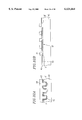
- FIG. 1 is an equivalent circuit diagram of a semiconductor device according to a first embodiment of the present invention
- FIG. 2 is a plan view of the semiconductor device according to the first embodiment of the present invention.
- FIG. 3 is a graph illustrating a cell current characteristic of a cell transistor of the semiconductor apparatus according to the first embodiment of the present invention
- FIG. 4 is a diagram for describing a read-out operation of a cell transistor of the NAND type of the semiconductor device according to the first embodiment of the present invention
- FIG. 5 is a diagram for describing a read-out operation of cell transistor of the NOR type of the semiconductor device according to the first embodiment of the present invention
- FIG. 6 is a cross-sectional view taken along the line A-A' in FIG. 2 illustrating a method for producing the semiconductor device according to the first embodiment of the present invention
- FIG. 7 is a cross-sectional view taken along the line A-A' in FIG. 2 illustrating a method for producing the semiconductor device according to the first embodiment of the present invention
- FIG. 8 is a cross-sectional view taken along the line A-A' in FIG. 2 illustrating a method for producing the semiconductor device according to the first embodiment of the present invention
- FIGS. 9A, 9B, 9C and 9D are cross-sectional views taken along the lines A-A', B-B', C-C' and B-B' in FIG. 2, respectively, illustrating a method for producing the semiconductor device according to the first embodiment of the present invention
- FIGS. 10A, 10B, 10C and 10D are cross-sectional views taken along the lines A-A', B-B', C-C' and B-B' in FIG. 2, respectively, illustrating a method for producing the semiconductor device according to the first embodiment of the present invention
- FIGS. 11A and 11B are cross-sectional views taken along the lines A-A' in FIG. 2 illustrating a method for producing the semiconductor device according to the first embodiment of the present invention
- FIGS. 12A, 12B and 12C are cross-sectional views taken along the lines A-A', B-B' and C-C' in FIG. 2, respectively, illustrating a method for producing the semiconductor device according to the first embodiment of the present invention
- FIG. 13 is a cross-sectional view taken along the line C-C' in FIG. 2 illustrating a method for producing a semiconductor device according to a second embodiment of the present invention
- FIG. 14 is a cross-sectional view taken along the line C-C' in FIG. 2 illustrating a method for producing a semiconductor device according to the second embodiment of the present invention
- FIG. 15 is a cross-sectional view taken along the line C-C' in FIG. 2 illustrating a method for producing a semiconductor device according to the second embodiment of the present invention
- FIG. 16 is a plan view of a semiconductor device according to a third embodiment of the present invention.
- FIG. 17 is a cross-sectional view taken along the line D-D' in FIG. 16 illustrating a method for producing a semiconductor device according to the second embodiment of the present invention
- FIG. 18 is a plan view of a semiconductor device according to a fourth embodiment of the present invention.
- FIG. 19 is a cross-sectional view taken along the line E-E' in FIG. 18 illustrating a method for producing the semiconductor device according to the fourth embodiment of the present invention.
- FIG. 20 is a cross-sectional view taken along the line E-E' in FIG. 18 illustrating a method for producing the semiconductor device according to the fourth embodiment of the present invention
- FIG. 21 is a cross-sectional view taken along the line E-E' in FIG. 18 illustrating a method for producing a semiconductor device according to a fifth embodiment of the present invention
- FIG. 22 is a cross-sectional view taken along the line E-E' in FIG. 18 illustrating a method for producing a semiconductor device according to a sixth embodiment of the present invention
- FIGS. 23A and 23B are cross-sectional view taken along the lines A-A' and B-B' in FIG. 2, respectively, illustrating a method for producing a semiconductor device according to a seventh embodiment of the present invention
- FIG. 24 is a cross-sectional view illustrating a method for producing a semiconductor device according to an eighth embodiment
- FIG. 25 is a plan view of a semiconductor device according to a ninth embodiment of the present invention.
- FIG. 26 is a cross-sectional view taken along the line A-A' in FIG. 25 illustrating a method for producing the semiconductor device according to the ninth embodiment of the present invention.
- FIGS. 27A and 27B are cross-sectional views taken along the line A-A' and B-B' in FIG. 25, respectively, illustrating a method for producing the semiconductor device according to the ninth embodiment of the present invention
- FIG. 28 is a cross-sectional view taken along the line A-A' in FIG. 25 illustrating a method for producing the semiconductor device according to the ninth embodiment of the present invention.
- FIGS. 29A and 29B are cross-sectional views taken along the line A-A' and B-B' in FIG. 25, respectively, illustrating a method for producing the semiconductor device according to the ninth embodiment of the present invention.
- FIGS. 30A and 30B are cross-sectional views taken along the lines A-A' and B-B' in FIG. 25, respectively, illustrating a method for producing the semiconductor device according to the ninth embodiment of the present invention
- FIG. 31 is a cross-sectional view taken along the line A-A' in FIG. 25 illustrating a method for producing the semiconductor device according to the ninth embodiment of the present invention.
- FIGS. 32A and 32B are cross-sectional views taken along the lines A-A' and B-B' in FIG. 25, respectively, illustrating a method for producing the semiconductor device according to the ninth embodiment of the present invention
- FIGS. 33A and 33B are cross-sectional views taken along the lines C-C' and B-B' in FIG. 25, respectively, illustrating a method for producing the semiconductor device according to the ninth embodiment of the present invention
- FIG. 34 is a cross-sectional view taken along the line B-B' in FIG. 25 illustrating a method for producing the semiconductor device according to the ninth embodiment of the present invention.
- FIG. 35B is a cross-sectional view taken along the line B-B' in FIG. 25, and FIG. 35A is a cross-sectional view taken along the line D-D' in FIG. 35B, both figures illustrating a method for producing the semiconductor device according to the ninth embodiment of the present invention.
- FIG. 36B is a cross-sectional view taken along the line B-B' in FIG. 25, and FIG. 36A is a cross-sectional view taken along the line D-D' in FIG. 36B, both figures illustrating a method for producing the semiconductor device according to the ninth embodiment of the present invention.
- FIG. 37 is a cross-sectional view taken along the line B-B' in FIG. 25 illustrating a method for producing the semiconductor device according to the ninth embodiment of the present invention.
- FIG. 38B is a cross-sectional view taken along the line B-B' in FIG. 25, and FIG. 38A is a cross-sectional view taken along the line D-D' in FIG. 38B, both figures illustrating a method for producing the semiconductor device according to the ninth embodiment of the present invention.
- FIGS. 39A, 39B and 39C are cross-sectional views taken along the line A-A', B-B' and C-C' in FIG. 25, respectively, illustrating the method for producing the semiconductor device according to the ninth embodiment of the present invention.
- FIGS. 40A, 40B and 40C are cross-sectional views taken along the lines A-A', B-B' and C-C' in FIG. 25, respectively, illustrating the method for producing the semiconductor device according to the ninth embodiment of the present invention
- FIGS. 41A, 41B and 41C are cross-sectional views taken along the lines A-A', B-B' and C-C' in FIG. 25, respectively, illustrating a method for producing a semiconductor device according to a tenth embodiment of the present invention
- FIGS. 42A, 42B and 42C are cross-sectional views taken along the lines A-A', B-B' and C-C' in FIG. 25, respectively, illustrating the method for producing the semiconductor device according to the tenth embodiment of the present invention
- FIGS. 43A and 43B are cross-sectional views taken along the lines A-A' and B-B' in FIG. 25, respectively, illustrating a method for producing a semiconductor device according to an eleventh embodiment of the present invention
- FIGS. 44A and 44B are cross-sectional views taken along the lines C-C' and B-B' in FIG. 25, respectively, illustrating the method for producing the semiconductor device according to the eleventh embodiment of the present invention
- FIGS. 45A, 45B and 45C are cross-sectional views taken along the lines A-A', B-B' and C-C' in FIG. 25, respectively, illustrating the method for producing the semiconductor device according to the eleventh embodiment of the present invention
- FIGS. 46A, 46B and 46C are cross-sectional views taken along the lines A-A', B-B' and C-C' in FIG. 25, respectively, illustrating the method for producing the semiconductor device according to the eleventh embodiment of the present invention
- FIG. 47 is a cross-sectional view taken along the line B-B' in FIG. 25 illustrating a method for producing a semiconductor device according to a twelfth embodiment of the present invention
- FIG. 48 is a cross-sectional view taken along the line B-B' in FIG. 25 illustrating a method for producing a semiconductor device according to a thirteenth embodiment of the present invention
- FIG. 49 is a cross-sectional view illustrating a method for producing a semiconductor device according to a fourteenth embodiment of the present invention.
- FIG. 50 is a plan view of a semiconductor device according to a fifteenth embodiment of the present invention.
- FIGS. 51A and 51B are cross-sectional views taken along the lines 51A--51A and 51B--51B in FIG. 50, respectively, illustrating the method for producing the semiconductor device according to the fifteenth embodiment of the present invention
- FIG. 52 is a plan view of the semiconductor device according to the fifteenth embodiment of the present invention.
- FIGS. 53A and 53B are cross-sectional views taken along the lines 53A--53A and 53B--53B in FIG. 52, respectively, illustrating a method for producing a semiconductor device according to a sixteenth embodiment of the present invention
- FIG. 54A is a plan view illustrating a first conventional example
- FIGS. 54B, 54C and 54D are cross-sectional views taken along the lines 54B--54B, 54C--54C and 54D--54D in FIG. 54A, respectively;
- FIG. 55A is a plan view illustrating a second conventional example
- FIGS. 55B and 55C are cross-sectional views taken along the lines 55B--55B and 55C--55C in FIG. 55A, respectively;
- FIG. 56A is a plan view illustrating a third conventional example
- FIGS. 56B and 56C are cross-sectional views taken along the lines 55B--55B and 55C--55C in FIG. 56A, respectively.
- FIGS. 1 through 5 illustrate a semiconductor device according to a first embodiment of the present invention.
- the semiconductor device of the first embodiment differs from the conventional high integration NOR-type ROM memory cells in that there is no high concentration diffusion wiring region such as sub-bit lines. Instead, it has a configuration where cell transistors 90 of the NAND-type ROMs are disposed. That is, it has a configuration where both cell transistors 100 of the NOR type and cell transistors 90 of the NAND type are present in the memory cell regions 110.
- the gate electrode which also functions as a word line is provided in the memory cell region in double layer configuration. That is, first layers of gate electrodes 7 are formed in the horizontal direction parallel to each other with a separation of a prescribed distance, and second layers of gate electrodes 10 are provided between the two neighboring gate electrodes 7. Therefore, the two gate electrodes 7 and 10 are parallel to each other.
- the expression that the two gate electrodes 7 and 10 are parallel includes not only the case where the two gate electrodes 7 and 10 are parallel to each other with a prescribed distance but also the case where ends of the two neighboring gate electrodes 7 and 10 are stacked on top of one another in the vertical direction.
- a plurality of channel portions 91 of the cell transistors 90 of the NAND type are directly connected and disposed, thereby using the region as the memory cell, which was used only for conventional wiring.
- the channel portions 101 of the cell transistors 100 of the NOR type which use the same gate electrode as the cell transistor 90, are disposed between the channel portions 91 of the cell transistor 90 of the NAND type. Because of this, the semiconductor device has a configuration where the portion of the semiconductor substrate 1 in the memory cell region under the gate electrodes 7 and 10 can be used as the channel region for each cell transistor. Therefore, high integration of memory cells can be achieved.
- a plurality of first gate electrodes 7 which also function as the first word lines are provided in the memory cell region 110, the gate electrodes 7 being parallel to each other in the first direction which corresponds to the left-to-right direction in the figures. Then, each of the second gate electrodes 10 which also function as the second word line is provided between the first gate electrodes 7.
- a plurality of selection lines 71 and 72 are provided along the first direction in the regions of both ends of the memory cell region 110 in a second direction which is perpendicular to the first direction.
- One group of the selection lines 71 are provided in the neighborhood of the bit line BL side and the other group of selection lines 72 are provided in the neighborhood of the ground line GL side.
- Each of the selection lines 71 and 72 is connected to a corresponding transistor 73. In such a configuration, if the selection lines 71 and 72 are selected by the selection line transistor 73 and the word line is selected, then the cell transistor in the prescribed address region is selected.
- the channel portions 91 of the cell transistors 90 of the NAND typ e extend in the second direction, and the channel portions 101 of the cell transistors 100 of the NOR-type extend in the second direction between the two neighboring channel portions 91.
- the end portion of the channel portion 91 of the bit line BL side is connected to the drawing electrode 5 (see FIG. 2).
- the channel portion 91 of the cell transistor 90 of the NAND type also functions as the source/drain of the cell transistor 100 of the NOR type.
- the threshold voltage V th of all the cell transistors 100 of the NOR type is higher than the threshold voltage V th of the cell transistors 90 of the NAND type.
- the write operation for ROM data are performed as follows. All cell transistors of the NAND-type are set at either the cell transistors (1) which become depletion-type or the cell transistors (2) which become enhancement-type. In all cell transistors of the NOR-type, the threshold voltage V th of all cell transistors (3) is set at an intermediate threshold voltage V th which is higher than the threshold voltage of enhancement-type cell transistors. Among the cell transistors (3) with the intermediate threshold voltage V th , the threshold voltage V th of selected cell transistor(s) (4) is set at a voltage which is higher than the voltage of the power supply. Accordingly, a selected cell transistor(s) (4) which can maintain a state of complete OFF can be produced.
- the selected word lines are set at the "L" level as illustrated in FIGS. 3 and 4. Then, the cell transistor 90 between the bit line BL and the ground line GL corresponding to the cell transistor column of the NAND type to be read-out makes conduction if it is the cell transistor(s) of (1) depletion-type and does not if it is the cell transistor(s) of (2) enhancement-type, thereby enabling the read operation.
- the selected word lines are set at "H" level as illustrated in FIGS. 3 and 5.
- the cell transistor 100 to be read-out between the bit line BL and the ground line GL corresponding to the cell transistor column of the NOR type to be read-out does not conduct if it is the transistor (4) with high threshold voltage V th of completely OFF and does conduct if it is the transistor (3) with the intermediate level threshold voltage V th , thereby enabling the read operation for the ROM data.
- the cell transistors 90 of the NAND type are all ON and, therefore, can be regarded as the wiring.
- bit lines BL corresponding to the cell transistor column of the NAND type and the bit lines BL corresponding to the cell transistor column of the NOR type are expressed as being separate bit lines, they are actually sharing the same line by selecting the current path by the selection lines 71 and 72 (see FIGS. 4 and 5).
- FIGS. 6-8, 9A-9D, 10A-10D, 11A and 11B and 12A-12C production steps for the semiconductor device according to the first embodiment will be described with reference to FIGS. 6-8, 9A-9D, 10A-10D, 11A and 11B and 12A-12C.
- an oxide film 2 is formed on the semiconductor substrate 1 as illustrated in FIG. 6.
- a resist pattern 3 is formed thereon as an ion implantation mask for an impurity having conductivity type reverse to that of the semiconductor substrate 1.
- ions 4 are implanted into the semiconductor substrate 1 from above the resist pattern 3. This produces a source/drain region 5 in the ion implantation region as illustrated in FIG. 7.
- This source/drain region 5 is used as the drawing electrode 5 from the cell transistors of the NAND type illustrated in FIG. 2.
- the above-described ion implantation is performed with arsenic ions (As + ) at an implantation density on the order of 10 15 cm -2 .
- the implantation energy is, for example, 40 keV.
- first gate oxide film 6 having a film thickness of 5 to 30 nm is formed on the semiconductor substrate 1 as illustrated in FIG. 7.
- a plurality of first gate electrodes 7 which become first word lines are formed parallel to each other on the gate oxide film 6.
- the first gate electrodes 7 are formed, for example, of an N + polysilicon film of 200 to 300 nm thickness, or have two-layer structure made of a lower N + polysilicon film of 100 nm thickness and an upper tungsten silicide film of 100 nm thickness.
- an insulating film is formed on the semiconductor substrate 1 so as to cover the first gate electrodes 7.
- This insulating film becomes a second gate insulating film 9 and an insulating film 8 between the gate electrodes.
- a plurality of second gate electrodes 10 which become second word lines are formed parallel to each other over the semiconductor substrate 1 through the second gate insulating film 9 and the insulating film 8 between the gate electrodes being inserted therebetween.
- the second gate electrodes 10 are provided between the first gate electrodes 7 so as to be parallel with the first gate electrodes 7.
- the second gate electrodes 10 are made, for example, of an N + polysilicon film of 200 to 300 nm thickness, or have two-layer structure made of a lower N + polysilicon film of 100 nm thickness and an upper tungsten silicide film of 100 nm thickness.
- the film material and the film thickness in such a manner that the ion implantation resistivity is the same for the first gate electrode 7 and the second gate electrode 10. If that is the case, the ion implantation to the cell transistors 90 of the NAND type and the cell transistors 100 of the NOR type, both connected to the first gate electrodes 7, and the ion implantation to the cell transistors 90 of the NAND type and the cell transistors 100 of the NOR type, both connected to the second gate electrodes 10, can be simultaneously performed during ion implantation for writing ROM data which is to be performed later. This reduces the number of necessary steps and improves production efficiency.
- Methods for forming the gate electrodes 7 and 10 also include a method of burying and etching back besides usual photolithography and dry etching, where the gate electrodes are formed in a self-aligning manner. According to this method, the overlapping of the first gate electrode 7 and the second gate electrode 10 can be prevented. It can also prevent another problem from happening that the implantation amount lacks in the overlapping region during the ion implantation for writing ROM data which is to be performed later.
- FIGS. 9A to 9D illustrate the steps for producing the cell transistors of the NOR type.
- implantation of ions 11 having the same conductivity type as the semiconductor substrate 1 is performed to portions (channel portions 101 of the cell transistors 100 of the NOR type) of seniconductor substrate 1 which are under the first gate electrodes 7 and the second gate electrodes 10 as illustrated in FIGS. 9B to 9D.
- the NAND-type cell transistors 100 are covered with the resist pattern 12 as illustrated in FIGS. 9A and 9C.
- the above-described ion-implantation onto the channel portions 101 is performed with boron ions (B + ) at implantation density on the order of 10 12 cm -2 .
- the implantation energy is, for example, 140 keV.
- This problem can be readily solved with a means provided as follows. That is, during the above-described ion implantation for raising the threshold voltage V th , the ion implantation 11 into the channel portions through the gate electrodes 7 and 10 with relatively high implantation energy is performed, as well as the punch-through preventing ion implantation 14 is simultaneously performed to the region where there are no gate electrodes with such a low implantation energy that they do not pass through the gate electrodes 7 and 10. If, for example, the cell transistors have the n-channel MOS structure, this punch-through preventing ion implantation is performed with boron ions (B + ) at an implantation density on the order of 10 12 to 10 13 cm -2 .
- the implantation energy is, for example, 20 to 50 keV.
- a punch-through voltage between the drawing electrodes 5 from the cell transistors of the NAND type also becomes a problem.
- these steps of ion implantation can be simultaneously performed in a single masking step. Therefore, according to the production steps of the first embodiment, the ion implantation for controlling the threshold voltage V th of the cell transistors of the NOR type and the ion implantation for preventing the punch-through can be performed simultaneously. This reduces the number of masking steps by one, thereby obtaining less expensive processing having simplified steps.
- FIGS. 10A to 10D illustrate the steps for producing the cell transistors of the NAND type.
- ion implantation 15 for making all the cell transistors to be depression-type is performed to the channel portions 91 of the cell transistors 90 of the NAND type.
- ROM data are written by selecting enhancement-type or depression-type transistors.
- the resist pattern 17 has been formed over the semiconductor substrate 1.
- steps illustrated in FIGS. 10A to 10D and those, steps illustrated in FIGS. 9A to 9D can be performed inter-changeably.
- the ion implantation 15 is performed with phosphorus ions (P + ) at the implantation density in the order of 10 12 to 10 13 cm -2 .
- the implantation energy is, for example, 300 to 400 keV.
- the ion implantation 16 for forming the source/drain of the cell transistors 90 of the NAND type can be performed at the same time as illustrated in FIGS. 10A and 10D.
- the diffusion region of the drawing electrode 5 and the source/drain portion 18 of the end region of the memory cells are connected (see FIG. 11A).
- the ion implantation for forming the source/drain is performed with arsenic ions (As + ) at the implantation density on the order of 10 15 cm -2 .
- the implantation energy is, for example, 40 keV.
- the ion implantation 15 for making depression-type transistors is performed on the channel portions through the gate electrodes 7 and 10 with high implantation energy, as well as the ion implantation 16 for making the source/drain is simultaneously performed on the region where no gate electrodes are present with such low implantation energy that the ions do not pass through the gate electrodes 7 and 10. Therefore, each ion implantation can be performed self-aligningly. This reduces the number of masking steps by one, thereby achieving simplified and less expensive processes.
- FIG. 11A illustrates the above-mentioned connection after the heat treatment step.
- a sufficient margin can be provided for the misalignment between the gate electrodes 7 and 10 of the first and second layers.
- the ion implantation 16 for forming the source/drain can be performed on the space 19 where no gate electrodes are present with relatively low implantation energy such that no ions pass through the gate electrode. Therefore, since the cell transistors 90 of the NAND type are connected with the source/drain region 20 implanted in the semiconductor substrate 1 as illustrated in FIG. 11B, non-connection between the cell transistors can be prevented.
- the ion implantation step for forming the source/drain after forming an insulating film interposed between the gate electrodes such as side wall insulating films over the second gate electrode 10. The reason is that the diffusion under the gate electrode can be inhibited by the film thickness of the insulating film interposed between the gate electrodes.
- the ROM data are written simultaneously on the cell transistors 90 of the NAND type and on the cell transistors 100 of the NOR type. Specifically, a resist pattern 21 is formed on the semiconductor substrate 1 as an implantation mask of the write operation for ROM data as illustrated in FIGS. 12A and 12B.
- part of the cell transistors 90 of the NAND type which are depression-type transistors, are converted into enhancement-type (indicated by regions marked with ⁇ and x) by implanting ions 22 (indicated by x) having the same conductivity type as the semiconductor substrate 1.
- the threshold voltage V th is selectively set almost the same as that of the power source by implanting ions 22 (indicated by x) having the same conductivity type as the semiconductor substrate 1, thereby selecting the transistors which are always OFF.
- Conditions for ion implantation for the write operation for ROM data are as follows. If the cell transistors have the n-channel MOS structure, then the ion implantation is performed with boron ions (B + ) at the implantation density on the order of 10 13 cm -2 .
- the implantation energy is, for example, 140 to 180 keV.
- the implantation for write operation for ROM data is performed only with boron ions (B + ). Therefore, the ion implantation can be performed with high implantation energy after stacking interlevel insulators, after opening the contact hole or during the step of forming metal wiring. Such high energy implantation is capable of improving the production efficiency and, therefore, contributes to less expensive production of semiconductor devices.
- the threshold value of the cell transistors 100 of the NOR type is allowed to take multiple values, then higher integration can further be achieved.
- the threshold voltage V th of the cell transistors of the NOR type are selectively varied to have four different values, the degree of integration changes from being of the factor of four to six when compared to the conventional single layer polysilicon process, and from two to three when compared to the double layer polysilicon process. Higher integration can further be achieved by having multiple values further.
- the ion implantation is performed for a plurality of times with differing ion implantation density corresponding to differing values of threshold voltage V th in the ion implantation steps for write operation for ROM data illustrated in FIGS. 12A to 12C.
- the interlevel insulator flattens the surface. Therefore, during the ion implantation for write operation for the ROM data in later steps, even if the first gate electrodes 7 and the second gate electrodes 10 overlap, the insufficient implantation of ions at the overlapped region can be avoided.
- the steps of forming metal wiring and interlevel insulator, forming the contact hole, forming the metal wiring, and forming the protective film are performed, which complete the first half of the production steps for the semiconductor device. Then, assembly steps in the remaining half are performed, and the semiconductor device of the first embodiment is produced.
- FIG. 13 corresponds to that shown in FIG. 9C
- FIGS. 14 and 15 correspond to that shown in FIG. 12C.
- the ion implantation 11 is performed with ions having the same conductivity type as the semiconductor substrate 1 as illustrated in FIG. 13 so that the threshold voltage V th of the cell transistors of the NOR type is raised to an intermediate level.
- the production steps up to this point are the same as in the first embodiment.
- the step illustrated in FIGS. 10A to 10D of making the cell transistors 90 of the NAND type to be depression-type by lowering the threshold voltage V th of the cell transistors differ from those in the first embodiment in that the ion implantation (corresponding to ion implantation 15 as shown in FIGS. 10A, 10C and 10D) for making the transistors to be depression-type is not performed, but only the ion implantation (corresponding to ion implantation 16 as shown in FIGS. 10A and 10D) for forming the source/drain of the cell transistors 90 is performed.
- the resist pattern 12 has been formed over the semiconductor substrate 1 as shown in FIG. 13 as described above.
- a resist pattern 30 is formed on the semiconductor substrate 1 as an implantation mask for writing ROM data, and parts of the cell transistors 90 of the NAND type, which are enhancement-type, are converted into depression-type by implanting ions 31 (indicated by ⁇ ) having the conductivity type reverse to that of the semiconductor substrate 1.
- implanting ions 31 indicated by ⁇
- the channel portions 101 of the cell transistors 100 of the NOR type are covered with the resist pattern 30.
- Conditions for the ion implantation for writing ROM data on the NAND side are as follows. If the cell transistors 90 are of the n-channel MOS structure, then phosphorus ions (P + ) are implanted at the implantation density on the order of 10 12 to 10 13 cm -2 .
- the implantation energy is, for example, 300 to 400 keV.
- the write operation for ROM data toward the cell transistors 100 of the NOR type is performed as follows. As illustrated in FIG. 15, a resist pattern 32 is formed on the semiconductor substrate 1 as an implantation mask for writing ROM data. Then, ions 33 (indicated by x) having the same conductivity type as the semiconductor substrate 1 are implanted into the cell transistors 100 of the NOR type, and the threshold voltage V th is selectively made above the power supply voltage to provide transistors which are always OFF (the region indicated by the double x). When this is being done, the channel portions 91 of the cell transistors 90 of the NAND type are covered with the resist pattern 32.
- Conditions for the ion implantation for writing ROM data of the NOR type are as follows. If the cell transistors 100 are of the n-channel MOS structure, then boron ions (B + ) are implanted at the implantation density on the order of 10 13 cm -2 .
- the implantation energy is, for example, 140 to 180 keV.
- the second embodiment is more advantageous than the first embodiment as to the following points.
- the type of the transistors changes from enhancement-type to depression-type and then again to enhancement-type. That is, the enhancement-type cell transistors are first converted into the depression-type cell transistors, and then back to the enhancement-type cell transistors.
- the enhancement-type cell transistors stay as they are. This simplifies the production steps and keeps the deviations of characteristics low, which are attributable to deviations of production conditions. Therefore, cell transistors having stable characteristics can be obtained.
- FIG. 16 illustrates a semiconductor device according to a third embodiment of the present invention
- FIG. 17 illustrates the production step therefor.
- the production step illustrated in FIG. 17 corresponds to that illustrated in FIG. 11A in the first embodiment.
- portions corresponding to those illustrated in FIG. 11A are designated by the same reference numerals, and the descriptions thereof are omitted.
- the space between the memory cell selection lines 71 and/or 72 of the third embodiment can be made less than the minimum processing line width of process of the first embodiment. That is, each pitch of the memory cell selection lines 71 and/or 72 of the third embodiment can be made smaller than that in the first embodiment, thereby further achieving higher integration.
- FIGS. 18 to 20 illustrate a semiconductor device according to a fourth embodiment of the present invention.
- This semiconductor device is such that the selection transistors 73 which select memory cells are depression-type transistors. That is, as illustrated in FIG. 18, portions of the semiconductor substrate 1 outside the memory cell region 95, which are below a plurality of selection lines 71 and 72 provided along the first direction, are connected to a plurality of depression-type transistors 73 (indicated by mesh) for each selection line. These selection transistors 73 are produced simultaneously in the step of forming the cell transistors of the NAND type.
- FIGS. 19 and 20 illustrate the cross-section taken along line E-E' in FIG. 18 in the order of the production step.
- the steps shown in FIGS. 19 and 20 correspond to the steps shown in FIGS. 10A and 11A.
- an oxide film 2 is formed on the semiconductor substrate 1.
- a resist pattern 3 is formed as an ion implantation mask for an impurity having the conductivity type reverse to that of the semiconductor substrate 1.
- ion implantation 4 for forming the source/drain is performed, thereby forming the source/drain region 5 in the semiconductor substrate 1 as shown in FIG. 7.
- This source/drain region 5 is used as the drawing electrode 5 from the cell transistors of the NAND type shown in FIG. 2.
- the steps illustrated in FIGS. 7 to 9 are performed.
- the ion implantation 15 for making the cell transistors to be depression-type and the ion implantation 16 for forming the source/drain of the cell transistor of the NAND type are performed at the same time.
- the resist pattern in the fourth embodiment, which is used as the ion implantation mask during the ion implantation 16 differs from that in the first embodiment in that the pattern has been changed such that the depression-type selection transistors can be formed at the same time (see FIG. 18). For this reason, as illustrated in FIGS. 19 and 20, by performing the ion implantation step similar to that described above, the depression-type selection line transistors 73 can be formed without increasing the number of production steps.
- the step for forming the selection line transistors 73 can be performed simultaneously with the step for converting the cell transistors of the NAND type into the depression-type transistors. This eliminates one masking step from the production steps in the first embodiment, and therefore, less expensive processing with simplified steps can be obtained.
- FIG. 21 illustrates a semiconductor device according to a fifth embodiment of the present invention.
- the first layer gate electrodes 7 and the second layer gate electrodes 10 of the cell transistors 90 of the NAND type are disposed on the semiconductor substrate 1 in such a manner that they are all separated.
- the ion implantation for forming the source/drain of the cell transistors 90 of the NAND type is performed on all the cell transistors 90.
- the step shown in FIG. 21 corresponds to the step shown in FIG. 17.
- FIG. 21 is a cross-sectional view of a certain transistor taken along line E-E'.
- the certain transistor is a transistor such as the one shown in FIG. 18, and a distance between the first and the second layer gate electrodes 7 and 10 is larger than a distance between the first and the second gate electrodes 7 and 10 shown in FIG. 18.
- the fifth embodiment there is a gap g formed between the first and second layer gate electrodes 7 and 10, through which the ion implantation 15 for forming the source/drain of the cell transistors 90 of the NAND type on the semiconductor substrate 1 can surely be performed. For this reason, according to the fifth embodiment, a semiconductor device from which stable read-out current can be obtained can be realized.
- FIG. 22 illustrates a semiconductor device according to a sixth embodiment of the present invention.
- the step shown in FIG. 22 corresponds to that shown in FIG. 20.
- the corresponding portions are designated by the same reference numerals and the descriptions thereof as are omitted.
- FIG. 22 is a cross-sectional view of a certain transistor taken along line E-E'.
- the certain transistor is a transistor such as the one shown in FIG. 18, and a distance between the first and the second layer gate electrodes 7 and 10 is larger than the distance between the first and the second gate electrodes 7 and 10 shown in FIG. 18.
- the configuration in the fifth embodiment is incorporated in that of the fourth embodiment.
- the gate electrode of the first layer and the gate electrode of the second layer are disposed with a predetermined distance.
- ion implantations for forming parts of the selection line transistors 73 and the cell transistors 90 are performed simultaneously as in the fourth embodiment.
- the ion implantation for forming the source/drain of the cell transistors 90 of the NAND type on the semiconductor substrate 1 is performed through a gap. The gap has a predetermined separation.
- a semiconductor device having both the effect described in the fourth embodiment and the effect described in the fifth embodiment can be realized.
- FIGS. 23A and 23B illustrate a semiconductor device according to a seventh embodiment of the present invention.
- the seventh embodiment differs from the first embodiment in that the drawing electrode 5 is formed after the first gate electrodes 7 are formed.
- the production steps will be described.
- a first gate oxide film 6 of 5 to 30 nm film thickness is formed on the semiconductor substrate 1, and then a plurality of gate electrodes 7 are formed on this gate oxide film 6 such that they are parallel to each other and extend in the first direction as described in the first embodiment.
- an N + polysilicon film of 200 to 300 nm thickness, or a double layer structure film made of a lower N + polysilicon film of 100 nm thickness and an upper tungsten silicide film of 100 nm thickness is used as the gate electrode 7.
- a resist pattern 3 is formed on the semiconductor substrate 1 and the first gate electrodes 7 as an ion implantation mask for impurity ions having the conductivity type reverse to that of the semiconductor substrate 1. Then, ions 4 for forming the source/drain are implanted from the above of the resist pattern 3 to form the source/drain region 5 on the semiconductor substrate 1, which are to be used as the drawing electrode 5 from the cell transistors of the NAND type.
- the second gate electrodes 9 are formed by the step such as the one shown in FIG. 8 in the first embodiment. Then, after performing the necessary steps similar to those in the first embodiment, the semiconductor device according to the seventh embodiment is produced.
- FIG. 24 illustrates a semiconductor device according to an eighth embodiment of the present invention.
- the step shown in FIG. 24 corresponds to the step shown in FIG. 11A of the first embodiment.
- the corresponding parts are designated by the same reference numerals and the detailed description thereof are omitted.
- the gate electrodes in the eighth embodiment have a single layer structure. That is, as illustrated in FIG. 24, a plurality of gate electrodes 7' similar to the first gate electrodes 7 of the first to the seventh embodiments are formed above the semiconductor substrate 1.
- a gate oxide film 6 is inserted between the plurality of gate electrodes 7' and the semiconductor substrate 1.
- the gate electrodes are of the single layer structure, it is inferior to those in the first to seventh embodiments in terms of high integration. However, since the number of steps is reduced, the production becomes simple and the production efficiency is improved.
- the semiconductor substrate 41 has a plurality of grooves 42 which are formed along the second direction, i.e., the direction perpendicular to the first direction along which the first and second gate electrodes 7 and 10 are provided.
- the gate electrodes of the cell transistors are formed over the bottom and the side surfaces of these grooves 42, and the channel regions of the cell transistors are formed beneath the bottom and the side surfaces of these grooves 42, so that higher integration is further realized. Embodiments of this type will be described hereinafter.
- FIGS. 25, 26, 27A, 27B, 28, 29A, 29B, 30A, 30B, 31, 32A, 32B, 33A, 33B, 34, 35A, 35B, 36A, 36B, 37, 38A, 38B, 39A-39C and 40A-40C illustrate a semiconductor device according to a ninth embodiment of the present invention.
- a plurality of grooves 42 extending in the second direction are formed on the semiconductor substrate 41.
- a plurality of first gate electrodes (first word lines) 44 extending in the first direction perpendicular to the direction of the grooves 42 are formed in parallel above the semiconductor substrate 41 including the grooves 42 with the first gate insulating film 43 inserted therebetween.
- second gate electrodes 46 are formed between the first gate electrodes 44 formed over the semiconductor substrate 41 including the grooves 42 with the second gate insulating film 45 inserted therebetween, the second gate electrodes 46 being parallel with the first gate electrodes 44.
- the channel portions 91 of the first cell transistors 90 of the NAND type are formed both beneath the upper surface of the semiconductor substrate 41 between the grooves 42 and beneath the bottom surface of the groove 42.
- the channel portions 101 of third cell transistors 100 of the NOR type are formed under the second gate electrodes 46 .
- the channel portions 91 of the second cell transistors 90 of the NAND type are formed both beneath the upper surface of the semiconductor substrate 41 between the grooves 42 and beneath the bottom surf ace of the groove 42.
- Formed in the side wall of the grooves 42 are the channel portions of fourth transistors of the NOR type.
- the semiconductor device has a structure where cell transistors 90 of the NAND type and the cell transistors 100 of the NOR type are simultaneously present in the memory cell region.
- the formation of the grooves 42 results in an increase in the area for forming the channel portions of the cell transistors when viewed from above. As a result, higher degree of integration than in each of the previous embodiments can further be realized.
- a plurality of grooves 42 are formed on the semiconductor substrate 41 in parallel along the second direction by a known method of etching.
- etching it is preferable to form the grooves 42 such that each groove has the depth corresponding to the channel length of the channel portions 101 of the aforementioned third and fourth cell transistors 100 of the NOR type to be formed in the side wall of the groove 42 in the later steps.
- the depth is preferably about 0.3 to 1.0 ⁇ m.
- an oxide film 49 is formed on the inner wall of the groove 42.
- the region other than the memory cell region is masked with a resist pattern 50, and ions are implanted into the semiconductor substrate 41 so as to control the threshold voltage V th of the channel portions of the third and fourth cell transistors to be formed in the side wall of the groove 42.
- ions 51 such as boron having the same conductivity type as the semiconductor substrate 41 are implanted at the implantation density on the order of about 10 12 cm -2 .
- the implantation energy is, for example, 20 to 50 keV.
- the ion implantation is performed in two oblique directions, each of which is defined as a direction which (i) constitutes an angle within the range of about 15° to 60° with respect to the normal axis of the semiconductor substrate 41; and (ii) extends on a plane which is perpendicular to both the side wall and the bottom surface of the groove 42.
- the implantation angle is chosen while taking the width and depth of the groove 42 into consideration such that the ions are implanted only to the side wall of the groove 42.
- the ions are not implanted there.
- the bottom surface of the groove 42 is blocked by the adjacent protrusion (the portion of the upper surface of the semiconductor substrate 41 between the grooves 42), the ions are not implanted there either.
- the oxide film 48 is removed and a side wall insulating film 52 is formed on the side wall of the groove 42.
- regions other than the memory cell regions are masked with the resist pattern 53 (see FIG. 29B) and ions 54 having the conductivity type reverse to that of the semiconductor substrate 41, for example phosphorus ions, are implanted so as to control the threshold voltage V th of the channel portions 91 of the aforementioned first and second cell transistors 90 to be formed both beneath the portions of the upper surface of the semiconductor substrate 41 between the grooves 42 and beneath the bottom surface of the groove 42.
- the ions are implanted at the implantation density in the order of 10 13 cm -2 .
- the implantation energy is, for example, 20 to 50 keV.
- the implantation angle is about 0° with respect to a normal to the semiconductor substrate 41.
- the threshold voltage V th of all the channel portions 91 of the cell transistors of the NAND type is set at low value, then the ion implantation with boron ions can be performed during the later step of writing ROM data. It is also possible and relatively easy to implant the ions into deeper locations, thereby improving the production efficiency.
- drawing electrodes 59 (see FIG. 25) from the memory cell region are formed. Specifically, as illustrated in FIGS. 30A and 30B, high concentration ions 55 having the conductivity type reverse to that of the semiconductor substrate 41 are implanted to form the drawing electrodes 59. The implantation of ions 55 is performed at the implantation density on the order of 10 15 cm -2 . When this is being done, regions for the channel portions are masked with the resist pattern 56 as illustrated in FIG. 30B.
- the side wall insulating film 52 is removed, and a first gate oxide film 43 of 5 to 30 nm film thickness is formed.
- a plurality of first gate electrodes 44 are formed in parallel over the semiconductor substrate 41 in the first direction with the first gate oxide film 43 being inserted therebetween.
- the first gate electrodes 44 are within the grooves 42.
- a second gate oxide film 45 of 5 to 30 nm film thickness is formed, and a plurality of second gate electrodes 46 are formed over the semiconductor substrate 41 in parallel in the first direction between the first gate electrodes 44 with the gate oxide film 45 being inserted therebetween.
- an N + polysilicon film of 200 to 300 nm thickness or a double layer structure made of a lower N + polysilicon film of 100 nm thickness and an upper tungsten silicide film of 100 nm thickness is used as the first and second gate electrodes 44 and 46.
- the semiconductor device of the present invention is the same as those in the previous embodiments.
- ions 58 are implanted with an angle of about 0° with respect to a normal to the semiconductor substrate 41 so as to connect the channel ends of the cell transistor of the NAND type and the above-mentioned drawing electrodes 59.
- high concentration ions 58 having conductivity type reverse to that of the semiconductor substrate 41 are implanted at an implantation density on the order of 10 15 cm -2 (in FIG. 34, the high concentration ions 58 are represented by ⁇ ).
- regions other than the channel portions are covered with the resist pattern 60.
- the ions 58 are not implanted into the channel portions of the cell transistors of the NOR type to be formed in the side wall of the grooves 42 because the side walls do not face the ion implantation.
- the ions are not implanted there.
- regions other than the memory cell region are masked with the resist pattern 62 as illustrated in FIGS. 35A and 35B.
- boron ions 200 having the same conductivity type as the semiconductor substrate 41 are implanted under conditions similar to those in the step shown in FIG. 28.
- the boron ions 200 are additionally implanted where the boron ions 51 have already been implanted. For this reason, isolation is surely achieved.
- the resist pattern 62 opens to the grooves 42 between the selection lines on the selection line side.
- the ions for isolation are also implanted to the side wall portion 63 of the grooves 42 (see FIG. 35). Therefore, the isolation between the upper surface and the bottom surface of the groove 42 are performed at the same time.
- the ions which form the source/drain are also implanted into the space 61 during the above-described ion implantation of the ions 58 (represented by ⁇ ), the connection between the channels of the channel portions 91 of the cell transistors 90 of the NAND type is surely achieved. Moreover, since the ion implantation density for the ions 58 is 10 15 cm -2 as described above, this ion implantation cancels the previous ion implantation for the isolation between the upper surface of the semiconductor substrate 41 and the bottom surface of the groove 42.
- FIG. 37 illustrates a situation where there is no space resulting from the misalignment between the first and second gate electrodes 44 and 46
- FIGS. 38A and 38B illustrate a situation where there is a space 61 resulting from the misalignment.
- a resist pattern 65 for writing ROM data corresponding to the ROM data to be written is formed, and ions 66 having the same conductivity type as the semiconductor substrate 41 such as boron ions are implanted from the above into the channel portions 91 of the cell transistors 90 of the NAND type beneath the upper surface of the groove 42 with relatively low implantation energy.
- ions 67 are implanted into the channel portions 91 of the cell transistors 90 of the NAND type beneath the bottom surface of the groove 42 to write the ROM data with relatively high implantation energy. Since the ion implantations into the upper surface of the groove 42 and into the bottom surface of the groove 42 have different implantation depths, one of the ion implantations does not affect the other.
- the write operation for ROM data is performed on the channel portions 101 of the cell transistors 100 of the NOR type.
- the writing is performed as illustrated in FIGS. 40A-40C.
- a resist pattern 68 for writing ROM data corresponding to the ROM data to be written is formed, and ions 69 having the same conductivity type as the semiconductor substrate 41 such as boron ions are implanted from the above into the side walls of the groove 42 with an intermediate implantation energy.
- the intermediate implantation energy is between the implantation energy to the upper surface of the groove 42 and the implantation energy to the bottom surface of the groove 42. Since this ion implantation also has the implantation depth different from the above-mentioned implantation depth, it does not affect the other.
- the ion implantations performed on the upper surface, the bottom surface and the side surface of the groove 42 during the write operation for the ROM data are independent in a sense that any one of the three does not affect the remaining two, the writing of the ROM data can be performed accurately on each surface of the groove 42.
- the first half of the production steps for the semiconductor device of the ninth embodiment is finished. Then, the last half of the production steps, i.e., the assembling steps are performed and the semiconductor device of the ninth embodiment illustrated in FIG. 25 is produced.
- FIGS. 41A-41C and 42A-42C illustrate a semiconductor device according to a tenth embodiment of the present invention.
- the semiconductor device in the tenth embodiment has the same configuration as the semiconductor device in the ninth embodiment, but the production steps are different as described below.
- the steps shown in FIGS. 41A to 41C correspond to the steps of writing ROM data shown in FIGS. 39A to 39C
- the steps shown in FIGS. 42A to 42C correspond to the steps of writing ROM data shown in FIGS. 40A to 40C.
- Parts corresponding to those in the ninth embodiment are designated by the same reference numerals, and the detailed descriptions thereof are omitted.
- an interlevel insulator 70 is formed on the semiconductor substrate 41 so as to cover the first gate electrode 44 and the second gate electrode 46. Then, after opening a contact hole in the interlevel insulator 70, or after forming metal wiring, the write operation for ROM data is performed on the upper surface, bottom surface and side surface of the groove 42 by performing ion implantation with each implantation energies.
- the implantation energy to the upper surface of the groove 42 in the tenth embodiment is higher than that in the ninth embodiment.
- the implantation energy to the side surface of the groove 42 in the tenth embodiment is higher than that in the ninth embodiment
- the implantation energy to the bottom surface of the groove 42 in the tenth embodiment is higher than that in the ninth embodiment.
- the production efficiency is improved compared to the ninth embodiment.
- FIGS. 43A, 43B, 44A, 44B, 45A-45C and 46A-46C illustrate a semiconductor device according to an eleventh embodiment of the present invention.
- the semiconductor device in the eleventh embodiment has a configuration such that the thicknesses of the first gate electrodes 44 and the second gate electrodes 46 are smaller than those in the previous embodiments.
- the production steps shown in FIGS. 43A and 43B correspond to the steps of forming the first gate electrodes in the ninth embodiment illustrated in FIGS. 32A and 32B
- the production steps shown in FIGS. 44A and 44B correspond to the steps of forming the second gate electrodes illustrated in FIGS. 33A and 33B.
- the production steps shown in FIGS. 45A to 45C correspond to the step of writing ROM data illustrated in FIGS.
- FIGS. 46A to 46C correspond to the step of writing ROM data shown in FIGS. 40A to 40C.
- the corresponding parts are designated by the same reference numerals. Parts corresponding to those in the ninth embodiment are designated by the same reference numerals, and the detailed description thereof are omitted.
- the eleventh embodiment illustrates a situation where the depth of the groove 42 is too wide particularly for the thickness of the gate electrodes 44 and 46 and, therefore, the gate electrodes 44 and 46 cannot be flattened perfectly (see FIGS. 43A and 44A). Because of this, in the eleventh embodiment, the steps of implanting ions having the conductivity type reverse to that of the semiconductor substrate 41 illustrated in FIGS. 28, 29A and 29B are omitted. And, when the writing of ROM data shown in FIGS. 45A to 45C is performed on the channel portions 91 of the cell transistors 90 of the NAND type, the ROM data are written by implanting ions 71, e.g., phosphorus ions having the conductivity type reverse to that of the semiconductor substrate 41, through a mask 165.
- implanting ions 71 e.g., phosphorus ions having the conductivity type reverse to that of the semiconductor substrate 41, through a mask 165.
- the write operation for ROM data on the channel portions 101 of the cell transistors 100 of the NOR type is performed as illustrated in FIGS. 46A to 46C by forming a resist pattern 68 which is patterned according to the ROM data and by implanting ions 69 such as boron ions as previously described.
- the ion implantation depths are different for the channel portions 91 of the cell transistors 90 of the NAND type and for the channel portions 101 of the cell transistors 100 of the NOR type. Therefore, one does not affect the other and the writing of ROM data can be accurately performed as in the eighth embodiment previously described.
- FIG. 47 illustrates a semiconductor device according to a twelfth embodiment of the present invention.
- the twelfth embodiment assumes that a semiconductor device has a space 61 between the first gate electrode 44 and the second gate electrode 46.
- a high concentration diffusion layer 64 is formed by implanting ions 58 which form the source/drain in the space 61 as in the above-described ninth embodiment, thereby surely connecting channels.
- FIG. 48 illustrates a semiconductor device according to a thirteenth embodiment of the present invention. Also in the thirteenth embodiment, the semiconductor device has a space 61 between the first gate electrode 44 and the second gate electrode 46 similarly as in the twelfth embodiment, and a high concentration diffusion layer 64 which becomes the source/drain is formed in the space 61.
- the thirteenth embodiment differs in the following points from each of the above-described embodiments where the semiconductor device has the groove 42.
- the step of forming the drawing electrode illustrated in FIGS. 30A and 30B is omitted, and the drawing electrodes 59 are simultaneously formed in the step of forming the source/drain region illustrated in FIG. 34.
- the drawing electrode wiring in the thirteenth embodiment are made of depression-type cell transistors.
- FIG. 49 illustrates a semiconductor device according to a fourteenth embodiment of the present invention.
- the semiconductor device in the fourteenth embodiment differs from those in the ninth to thirteenth embodiments in that the gate electrodes are of a single layer structure.
- the production step shown in FIG. 49 corresponds to the production steps before the ion implantation for writing ROM data illustrated in FIG. 47.
- the gate electrodes are of the single layer structure, it is inferior to those in the ninth to thirteenth embodiments in terms of high integration. However, the production steps are simplified and the production efficiency can be improved.
- FIGS. 50, 51A and 51B illustrate a semiconductor device according to a fifteenth embodiment of the present invention.
- the semiconductor device in the fifteenth embodiment has the same structure as the semiconductor device in the ninth embodiment except the following.
- the corresponding parts are designated by the same reference numerals and the descriptions thereof are omitted. Only the portions which are different will be described below.
- the channel portions of the first cell transistors 90 of the NAND type are formed in the side wall of the groove 42 under the first gate electrode 44, and the channel portions of the third cell transistors 100 of the NOR type are formed both beneath the upper surface of the semiconductor substrate 41 between the grooves 42 and beneath the bottom surface of the groove 42.
- the channel portions 91 of the second cell transistors 90 of the NAND type are formed in the side wall of the groove 42 under the second gate electrode 46, and the channel portions 101 of the fourth cell transistors 100 of the NOR type are formed both beneath the upper surface of the semiconductor substrate 41 between the grooves 42 and beneath the bottom surface of the groove 42.
- the locations of the formation of the channel portions 91 of the cell transistors 90 of the NAND type and of the channel portions 101 of the cell transistors 100 of the NOR type with respect to the groove 42 in the semiconductor device in the ninth embodiment are reversed for the semiconductor device in the fourteenth embodiment.
- FIGS. 52, 53A and 53B illustrate a semiconductor device according to a sixteenth embodiment of the present invention.
- the first gate electrodes 44 which become the first word lines are formed over both side walls of the groove 42
- the second gate electrodes 46 and 46' which become the second word lines are formed over the bottom surface of the groove 42 and over the upper surface of the semiconductor substrate 41 between the grooves 42, thereby achieving a structure where higher integration of memory cells can be realized.
- the semiconductor device in the sixteenth embodiment differs from those in the ninth to fifteenth embodiments in that the grooves 42 are formed in the first direction.
- the side wall gate electrodes (first gate electrodes) 44 which become the first word lines with the first gate insulating films 43 being inserted therebetween.
- the bottom surface gate electrodes (second gate electrodes) 46 which become the second word lines are formed on the bottom surface of the grooves 42 with the second gate insulating film 45 being inserted therebetween.
- the upper surface gate electrodes 46' which become the second word lines are also formed over the upper surface of the semiconductor substrate 41 between the groove 42 with the second gate insulating film 45 being inserted therebetween.
- channel portions 91 of the cell transistors 90 of the NAND type and the channel portions 101 of the cell transistors 100 of the NOR type are alternately formed in the second direction which is perpendicular to the first direction over the upper surfaces, side walls and the bottom surfaces of the semiconductor substrate 41 between the grooves 42.
- NAND-type cell transistors and NOR-type cell transistors are simultaneously present, and they are disposed in the memory cell region of the semiconductor substrate such that the channel region of each cell transistor makes contact with the neighboring channel region. Therefore, the degree of integration of the cell transistors both in the first direction which is the wiring direction of the word lines and in the second direction which is perpendicular to the first direction can be improved, thereby realizing high integration of the memory cells. Therefore, according to the present invention, larger storage capacity of the semiconductor device including mask ROMs can be achieved, and the production cost can be considerably reduced due to the smaller size of a chip.
- the threshold voltage of the cell transistor of the NOR type selectively differs, then the threshold voltage takes, for example, four values and the integration is four times to six times greater as compared to the first embodiment.
- a plurality of grooves are formed on the semiconductor substrate.
- the gate electrodes of the cell transistors are formed over the upper surface of the semiconductor substrate between the grooves and the bottom surface and side wall of the groove, and the channel regions of the cell transistors are formed beneath the upper surface of the semiconductor substrate between the grooves and the bottom surface and side wall of the groove.
- either of the first word lines or the second word lines are formed over the upper surface of the semiconductor substrate between the grooves and over the bottom surface of the groove with an insulating film being inserted therebetween, and the other word lines are formed on the side walls of the grooves. Therefore, the wiring pitch in the plan view can further be made small, thereby further achieving the higher integration.
- each of the production steps described above can be performed in an arbitrary order. Therefore, if the ion implantation step for writing ROM data is to be performed simultaneously for both the NAND side and the NOR side using one mask, the write operation for ROM data requires only one step of ion implantation. This simplifies the production steps, thereby improving the production efficiency for the semiconductor device.
Landscapes
- Semiconductor Memories (AREA)
- Non-Volatile Memory (AREA)
Applications Claiming Priority (2)
| Application Number | Priority Date | Filing Date | Title |
|---|---|---|---|
| JP5523596 | 1996-03-12 | ||
| JP8-055235 | 1996-03-12 |
Publications (1)
| Publication Number | Publication Date |
|---|---|
| US6121664A true US6121664A (en) | 2000-09-19 |
Family
ID=12992950
Family Applications (1)
| Application Number | Title | Priority Date | Filing Date |
|---|---|---|---|
| US08/811,785 Expired - Fee Related US6121664A (en) | 1996-03-12 | 1997-03-06 | Semiconductor memory device |
Country Status (3)
| Country | Link |
|---|---|
| US (1) | US6121664A (fr) |
| KR (1) | KR100259834B1 (fr) |
| TW (1) | TW322634B (fr) |
Cited By (3)
| Publication number | Priority date | Publication date | Assignee | Title |
|---|---|---|---|---|
| US6525954B2 (en) * | 2000-09-29 | 2003-02-25 | Artisan Components, Inc. | Method and apparatus for a dense metal programmable ROM |
| US6764890B1 (en) * | 2003-01-29 | 2004-07-20 | Cypress Semiconductor Corporation | Method of adjusting the threshold voltage of a mosfet |
| US20050090085A1 (en) * | 2003-10-23 | 2005-04-28 | Micron Technology, Inc. | NAND memory arrays |
Families Citing this family (1)
| Publication number | Priority date | Publication date | Assignee | Title |
|---|---|---|---|---|
| JP4036552B2 (ja) * | 1998-12-17 | 2008-01-23 | 富士通株式会社 | 不揮発性半導体記憶装置 |
Citations (6)
| Publication number | Priority date | Publication date | Assignee | Title |
|---|---|---|---|---|
| JPS5341188A (en) * | 1976-08-25 | 1978-04-14 | Hitachi Ltd | Mis type semiconductor device |
| JPS63131568A (ja) * | 1986-11-21 | 1988-06-03 | Toshiba Corp | 半導体メモリ装置 |
| US4974042A (en) * | 1987-07-27 | 1990-11-27 | Sharp Kabushiki Kaisha | Semiconductor memory device with compact ROM memory cells |
| US5453392A (en) * | 1993-12-02 | 1995-09-26 | United Microelectronics Corporation | Process for forming flat-cell mask ROMS |
| US5578857A (en) * | 1993-07-14 | 1996-11-26 | United Microelectronics Corporation | Double poly high density buried bit line mask ROM |
| US5859460A (en) * | 1995-09-19 | 1999-01-12 | United Microelectronics Corporation | Tri-state read-only memory device and method for fabricating the same |
-
1997
- 1997-03-06 TW TW086102753A patent/TW322634B/zh not_active IP Right Cessation
- 1997-03-06 US US08/811,785 patent/US6121664A/en not_active Expired - Fee Related
- 1997-03-11 KR KR1019970009003A patent/KR100259834B1/ko not_active Expired - Fee Related
Patent Citations (6)
| Publication number | Priority date | Publication date | Assignee | Title |
|---|---|---|---|---|
| JPS5341188A (en) * | 1976-08-25 | 1978-04-14 | Hitachi Ltd | Mis type semiconductor device |
| JPS63131568A (ja) * | 1986-11-21 | 1988-06-03 | Toshiba Corp | 半導体メモリ装置 |
| US4974042A (en) * | 1987-07-27 | 1990-11-27 | Sharp Kabushiki Kaisha | Semiconductor memory device with compact ROM memory cells |
| US5578857A (en) * | 1993-07-14 | 1996-11-26 | United Microelectronics Corporation | Double poly high density buried bit line mask ROM |
| US5453392A (en) * | 1993-12-02 | 1995-09-26 | United Microelectronics Corporation | Process for forming flat-cell mask ROMS |
| US5859460A (en) * | 1995-09-19 | 1999-01-12 | United Microelectronics Corporation | Tri-state read-only memory device and method for fabricating the same |
Cited By (4)
| Publication number | Priority date | Publication date | Assignee | Title |
|---|---|---|---|---|
| US6525954B2 (en) * | 2000-09-29 | 2003-02-25 | Artisan Components, Inc. | Method and apparatus for a dense metal programmable ROM |
| US6764890B1 (en) * | 2003-01-29 | 2004-07-20 | Cypress Semiconductor Corporation | Method of adjusting the threshold voltage of a mosfet |
| US20050090085A1 (en) * | 2003-10-23 | 2005-04-28 | Micron Technology, Inc. | NAND memory arrays |
| US7419895B2 (en) * | 2003-10-23 | 2008-09-02 | Micron Technology, Inc. | NAND memory arrays |
Also Published As
| Publication number | Publication date |
|---|---|
| TW322634B (fr) | 1997-12-11 |
| KR100259834B1 (ko) | 2000-06-15 |
| KR970067904A (ko) | 1997-10-13 |
Similar Documents
| Publication | Publication Date | Title |
|---|---|---|
| US6214669B1 (en) | Single-chip contact-less read-only memory (ROM) device and the method for fabricating the device | |
| US5691938A (en) | Non-volatile memory cell and array architecture | |
| US6376879B2 (en) | Semiconductor device having MISFETs | |
| JP3251164B2 (ja) | 半導体装置及びその製造方法 | |
| US7195967B2 (en) | Nonvolatile semiconductor memory device and manufacturing method thereof | |
| US4839705A (en) | X-cell EEPROM array | |
| US6130838A (en) | Structure nonvolatile semiconductor memory cell array and method for fabricating same | |
| US6239500B1 (en) | Semiconductor device with common bit contact area | |
| US20090039407A1 (en) | Vertically integrated flash EPROM for greater density and lower cost | |
| US6232182B1 (en) | Non-volatile semiconductor memory device including memory transistor with a composite gate structure and method of manufacturing the same | |
| US20070004134A1 (en) | Vertically integrated flash EPROM for greater density and lower cost | |
| US5576573A (en) | Stacked CVD oxide architecture multi-state memory cell for mask read-only memories | |
| JPH04226071A (ja) | 半導体メモリ装置 | |
| US6307217B1 (en) | Semiconductor memory device having driver and load MISFETs and capacitor elements | |
| US20070001212A1 (en) | NAND-type memory devices including recessed source/drain regions and related methods | |
| US20060118856A1 (en) | Twin EEPROM memory transistors with subsurface stepped floating gates | |
| US6121664A (en) | Semiconductor memory device | |
| US7375387B2 (en) | Method for producing semiconductor memory devices and integrated memory device | |
| US20010017800A1 (en) | Cell array region of a NOR-type mask ROM device and fabricating method therefor | |
| US7180788B2 (en) | Nonvolatile semiconductor memory device | |
| JPH0479370A (ja) | 不揮発性半導体記憶装置 | |
| US5828113A (en) | Double density MROM array structure | |
| US5936889A (en) | Array of nonvolatile memory device and method for fabricating the same | |
| JP3531708B2 (ja) | 半導体装置及びその製造方法 | |
| JP2002208645A (ja) | 不揮発性半導体記憶装置およびその製造方法 |
Legal Events
| Date | Code | Title | Description |
|---|---|---|---|
| AS | Assignment |
Owner name: SHARP KABUSHIKI KAISHA, JAPAN Free format text: ASSIGNMENT OF ASSIGNORS INTEREST;ASSIGNOR:AOKI, HITOSHI;REEL/FRAME:008422/0334 Effective date: 19970224 |
|
| FEPP | Fee payment procedure |
Free format text: PAYOR NUMBER ASSIGNED (ORIGINAL EVENT CODE: ASPN); ENTITY STATUS OF PATENT OWNER: LARGE ENTITY |
|
| FPAY | Fee payment |
Year of fee payment: 4 |
|
| FPAY | Fee payment |
Year of fee payment: 8 |
|
| REMI | Maintenance fee reminder mailed | ||
| LAPS | Lapse for failure to pay maintenance fees | ||
| STCH | Information on status: patent discontinuation |
Free format text: PATENT EXPIRED DUE TO NONPAYMENT OF MAINTENANCE FEES UNDER 37 CFR 1.362 |
|
| FP | Lapsed due to failure to pay maintenance fee |
Effective date: 20120919 |