US6132011A - Brake pressure control device - Google Patents
Brake pressure control device Download PDFInfo
- Publication number
- US6132011A US6132011A US08/920,213 US92021397A US6132011A US 6132011 A US6132011 A US 6132011A US 92021397 A US92021397 A US 92021397A US 6132011 A US6132011 A US 6132011A
- Authority
- US
- United States
- Prior art keywords
- brake pressure
- motor
- valve block
- connector
- electronic control
- Prior art date
- Legal status (The legal status is an assumption and is not a legal conclusion. Google has not performed a legal analysis and makes no representation as to the accuracy of the status listed.)
- Expired - Fee Related
Links
Images


Classifications
-
- B—PERFORMING OPERATIONS; TRANSPORTING
- B60—VEHICLES IN GENERAL
- B60T—VEHICLE BRAKE CONTROL SYSTEMS OR PARTS THEREOF; BRAKE CONTROL SYSTEMS OR PARTS THEREOF, IN GENERAL; ARRANGEMENT OF BRAKING ELEMENTS ON VEHICLES IN GENERAL; PORTABLE DEVICES FOR PREVENTING UNWANTED MOVEMENT OF VEHICLES; VEHICLE MODIFICATIONS TO FACILITATE COOLING OF BRAKES
- B60T8/00—Arrangements for adjusting wheel-braking force to meet varying vehicular or ground-surface conditions, e.g. limiting or varying distribution of braking force
- B60T8/32—Arrangements for adjusting wheel-braking force to meet varying vehicular or ground-surface conditions, e.g. limiting or varying distribution of braking force responsive to a speed condition, e.g. acceleration or deceleration
- B60T8/34—Arrangements for adjusting wheel-braking force to meet varying vehicular or ground-surface conditions, e.g. limiting or varying distribution of braking force responsive to a speed condition, e.g. acceleration or deceleration having a fluid pressure regulator responsive to a speed condition
- B60T8/36—Arrangements for adjusting wheel-braking force to meet varying vehicular or ground-surface conditions, e.g. limiting or varying distribution of braking force responsive to a speed condition, e.g. acceleration or deceleration having a fluid pressure regulator responsive to a speed condition including a pilot valve responding to an electromagnetic force
- B60T8/3605—Arrangements for adjusting wheel-braking force to meet varying vehicular or ground-surface conditions, e.g. limiting or varying distribution of braking force responsive to a speed condition, e.g. acceleration or deceleration having a fluid pressure regulator responsive to a speed condition including a pilot valve responding to an electromagnetic force wherein the pilot valve is mounted in a circuit controlling the working fluid system
-
- B—PERFORMING OPERATIONS; TRANSPORTING
- B60—VEHICLES IN GENERAL
- B60T—VEHICLE BRAKE CONTROL SYSTEMS OR PARTS THEREOF; BRAKE CONTROL SYSTEMS OR PARTS THEREOF, IN GENERAL; ARRANGEMENT OF BRAKING ELEMENTS ON VEHICLES IN GENERAL; PORTABLE DEVICES FOR PREVENTING UNWANTED MOVEMENT OF VEHICLES; VEHICLE MODIFICATIONS TO FACILITATE COOLING OF BRAKES
- B60T8/00—Arrangements for adjusting wheel-braking force to meet varying vehicular or ground-surface conditions, e.g. limiting or varying distribution of braking force
- B60T8/32—Arrangements for adjusting wheel-braking force to meet varying vehicular or ground-surface conditions, e.g. limiting or varying distribution of braking force responsive to a speed condition, e.g. acceleration or deceleration
- B60T8/34—Arrangements for adjusting wheel-braking force to meet varying vehicular or ground-surface conditions, e.g. limiting or varying distribution of braking force responsive to a speed condition, e.g. acceleration or deceleration having a fluid pressure regulator responsive to a speed condition
- B60T8/36—Arrangements for adjusting wheel-braking force to meet varying vehicular or ground-surface conditions, e.g. limiting or varying distribution of braking force responsive to a speed condition, e.g. acceleration or deceleration having a fluid pressure regulator responsive to a speed condition including a pilot valve responding to an electromagnetic force
- B60T8/3615—Electromagnetic valves specially adapted for anti-lock brake and traction control systems
- B60T8/3675—Electromagnetic valves specially adapted for anti-lock brake and traction control systems integrated in modulator units
- B60T8/368—Electromagnetic valves specially adapted for anti-lock brake and traction control systems integrated in modulator units combined with other mechanical components, e.g. pump units, master cylinders
-
- B—PERFORMING OPERATIONS; TRANSPORTING
- B60—VEHICLES IN GENERAL
- B60T—VEHICLE BRAKE CONTROL SYSTEMS OR PARTS THEREOF; BRAKE CONTROL SYSTEMS OR PARTS THEREOF, IN GENERAL; ARRANGEMENT OF BRAKING ELEMENTS ON VEHICLES IN GENERAL; PORTABLE DEVICES FOR PREVENTING UNWANTED MOVEMENT OF VEHICLES; VEHICLE MODIFICATIONS TO FACILITATE COOLING OF BRAKES
- B60T13/00—Transmitting braking action from initiating means to ultimate brake actuator with power assistance or drive; Brake systems incorporating such transmitting means, e.g. air-pressure brake systems
- B60T13/74—Transmitting braking action from initiating means to ultimate brake actuator with power assistance or drive; Brake systems incorporating such transmitting means, e.g. air-pressure brake systems with electrical assistance or drive
-
- B—PERFORMING OPERATIONS; TRANSPORTING
- B60—VEHICLES IN GENERAL
- B60T—VEHICLE BRAKE CONTROL SYSTEMS OR PARTS THEREOF; BRAKE CONTROL SYSTEMS OR PARTS THEREOF, IN GENERAL; ARRANGEMENT OF BRAKING ELEMENTS ON VEHICLES IN GENERAL; PORTABLE DEVICES FOR PREVENTING UNWANTED MOVEMENT OF VEHICLES; VEHICLE MODIFICATIONS TO FACILITATE COOLING OF BRAKES
- B60T8/00—Arrangements for adjusting wheel-braking force to meet varying vehicular or ground-surface conditions, e.g. limiting or varying distribution of braking force
- B60T8/32—Arrangements for adjusting wheel-braking force to meet varying vehicular or ground-surface conditions, e.g. limiting or varying distribution of braking force responsive to a speed condition, e.g. acceleration or deceleration
- B60T8/34—Arrangements for adjusting wheel-braking force to meet varying vehicular or ground-surface conditions, e.g. limiting or varying distribution of braking force responsive to a speed condition, e.g. acceleration or deceleration having a fluid pressure regulator responsive to a speed condition
- B60T8/36—Arrangements for adjusting wheel-braking force to meet varying vehicular or ground-surface conditions, e.g. limiting or varying distribution of braking force responsive to a speed condition, e.g. acceleration or deceleration having a fluid pressure regulator responsive to a speed condition including a pilot valve responding to an electromagnetic force
- B60T8/3615—Electromagnetic valves specially adapted for anti-lock brake and traction control systems
- B60T8/363—Electromagnetic valves specially adapted for anti-lock brake and traction control systems in hydraulic systems
Definitions
- This invention relates to a brake pressure control device for a vehicle equipped with an antilock brake system (ABS), a traction control system (TCS) or other device which electronically controls the brake pressure of the wheels; more specifically, it relates to a brake pressure control device with an improved power supply system to the motor for driving the hydraulic pump in the brake pressure unit.
- ABS antilock brake system
- TCS traction control system
- An integrated type of brake pressure control device is publicly known, comprised of a brake pressure unit equipped, in the main, with a plural number of solenoid valves, a hydraulic pump and a motor to drive these parts, and an electronic control unit which controls the power supply to said parts.
- This latter electronic control unit is integrally attached to the brake pressure unit to form a single unit.
- the aforementioned motor is equipped with a power supply harness with attached connector which is mounted to straddle the exterior of the brake pressure unit, and is connected to the connector molded on the electronic control unit.
- the aforementioned external wiring of the motor requires said power supply harness for the motor, as well as a connector for each of said harness and the electronic control unit, all of which prohibits a low cost unit.
- a separate relay harness is also connected to the electronic control unit, and the need for two harnesses increases the complexity of the design for the harness wiring and for the positioning of the multiple connectors.
- the objective of this invention is to provide a brake pressure control unit which eliminates the need for external harness wiring, thereby making the unit more compact, less costly, more waterproof, and/or easier to assemble and disassemble.
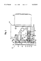
- FIG. 1 is a diagram of the brake pressure control device as a whole with a portion of the components exposed.
- FIG. 2 is a cross section diagram of the brake pressure control device of FIG. 1 as viewed when dissected through II--II.
- FIG. 3 is a cross section diagram of the brake pressure control device of FIG. 1 of FIG. 1 as viewed when dissected through III--III.
- FIG. 4 is a cross section diagram of the brake pressure control device of FIG. 1 of FIG. 1 as viewed when dissected through IV--IV.
- FIG. 5 is a diagram of the power supply for the motor comprised of the male motor connector and the female cover connector.
- FIG. 6 illustrates another embodiment of the invention in which the wiring tube has been configured into a separate unit.
- FIG. 7 illustrates an alternative embodiment for attaching the wiring tube to the control substrate.
- FIG. 8 illustrates an alternative embodiment of the invention where the male motor connector of the motor is integrally molded with the brush terminal, and the insulating cover of the motor terminal is integrally molded with the brush holder.
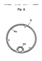
- FIG. 9 is a planar diagram of a preferred arrangement of a seal ring between the valve block and the motor.
- a novel brake pressure control device comprising: a brake pressure unit equipped with a plurality of solenoid valves, a cover for said solenoid valves; a hydraulic pump and a motor to drive said hydraulic pump; and an electronic control unit which operates the solenoid valves and the motor of said brake pressure unit.
- a wiring cavity is located within said brake pressure unit, a pair of electrical contacts protrude from the motor to form a male motor connector, a pair of electrical contacts protrude from the cover to form a female cover connector which can be connected to or disconnected from said male motor connector, the male connector thus formed and set inside said wiring cavity and the female cover connector thus formed comprise the power supply to the motor, and the base end of the terminals of said female cover connector are connected directly to the control print circuit board.
- a novel brake pressure control device in which the control print circuit board of the electronic control unit is set inside said cover and the electronic control unit so configured is integrated with the brake pressure unit into a single unit, and the female cover connector makes an electrical connection with the control print circuit board by means of a relay conductor.
- a novel brake pressure control device wherein said relay conductor making the electrical connection is a flexible printed circuit (FPC) comprised of a band conductor laminated onto a flexible insulating substrate.
- FPC flexible printed circuit
- FIGS. 1-5 illustrate an example of an integrated brake pressure control unit comprised of a brake pressure unit 10 and an electronic control unit 20 connected so as to form a single unit.
- the brake pressure unit 10 is comprised of a valve block 30 in which at least two solenoid valves 40 are mounted (FIG. 1).
- a hydraulic pump, housed inside said valve block 30, is driven by a motor 50 mounted on the right end (as shown in the diagram) of said valve block.
- an internal wiring cavity 31 is bored to be virtually parallel to the axis of rotation of the motor within said valve block. Said wiring hole 31 functions as a space to hold the wires for the motor 50, to be described later.
- valve block 30 Also molded to a portion of said valve block 30 are ports 32 to which are connected the lines to supply brake fluid to each wheel cylinder. Brake fluid to these lines is supplied via a line connected from the master cylinder to said valve block.
- the solenoid valve 40 is a publicly-known type of electromagnetically-actuated valve comprised of a dome-shaped valve component 41 and a cylindrical coil 42 mounted externally around said valve component 41 (FIG. 1).
- a normally-open or normally-closed valve mechanism is housed inside said valve component 41, and the electromagnetic force of the coil 42 causes the internal valve body to open or close the brake fluid channels.
- a cover body 21 and cover 22 are set on the side face at the left-end (of the diagram) of the valve block 30, and are affixed so as to be detachable by means of a through bolt or other fastener.
- each coil 42 is fixed by the protrusion 21b protruding from the inner face of the partition 21a of said cover body 21 pressing against the head of said coil.
- the coil 42 is mounted on the cover body 21 side to enable the brake pressure unit 10 to be separated from the electronic unit 20.
- a wiring tube 21c of a length so as to abut against the valve block 30 is integrally molded on the inner side of the partition 21a at a position separate from the protrusion 21b.
- a wiring cavity 21d is bored inside said wiring tube 21c.
- the control print circuit board 23 is set on the outer side of said partition 21a, and is mounted onto the cover body 21 by means of a publicly-known cylindrical boss, set screw, or other fastening mechanism. Said control print circuit board 23 contains the electronic components 24 of the electronic control unit, as well as holes in which to inlay the contact terminals 43, 43 of the coil 42, and the terminals for insertion and connection of the relay conductor 63 to be discussed later.
- the cover 22 is mounted on the partition 21a side of the cover body 21, and serves to protect said control print circuit board 23. Moreover, as shown in FIG. 2 and FIG. 3, a connector 27 is integrally molded onto a portion of the cover 22 such that it can be connected electrically to an external harness not shown in the diagram.
- a sealing material 25 is set around the entire perimeter of the cover body 21 on the opening side and a sealing material 26 is set around the entire perimeter of said cover body on the partition side to form a tight waterproof seal between the valve block 30 and cover body 21, and between the cover body 21 and the cover 22 respectively.
- a water drainage hole 28 is affixed into the cover body 21.
- This invention uses the internal wiring cavity 31 in the brake pressure unit 10 and the wiring cavity 21d inside the wiring tube 21c for the wiring of the motor 50. That is, as shown in FIG. 1, the motor 50 has a male motor connector comprised of a pair of protruding contacts 51, 51 extending axially from the motor, the greater portion of which are encased in an insulating layer 52 made, for example, from a resin mold, and only the tips are exposed. The diameter of said insulating layer is large enough so as to be enclosed in the mouth of the internal wiring cavity 31.
- the cover has a female cover connector, comprised of a pair of cover contacts 60, 60 inserted into the wiring cavity 21d of the cover body 21 such that their removal is restricted.
- the mouth of the wiring cavity 21d is closed off with the sealing material 61, leaving the upper portion of the cover contacts 60, 60 protruding out of said sealant.
- Said female cover connector 60 has a receptacle segment 62, wherein an electrical connection is made by plugging the male motor connector 51 into said receptacle 62 and is severed by pulling out the motor 50 and its attached male connector 51.
- This male motor connector 51 and the female cover connector 60 as shown in FIG. 5, comprise the power supply conductor to the motor 50.
- the receptacle 62 can instead be molded onto the motor with the male and female connectors reversed.
- the area between the exposed portion of the cover contacts 60, 60 and the control print circuit board 23 can be connected electrically by means of the relay conductor 63.
- the relay conductor 63 Aside from a conductive plate, other components that could be used as said relay conductor 63 include a flexible printed circuit (FPC) which is a busbar configured from a flexible insulating substrate laminated with a band conductor.
- FPC flexible printed circuit
- the power transmitted from the control print circuit board 23 is supplied via the relay conductor 63 and the female cover connector 60 to the male motor connector 51 to drive the motor.
- control print circuit board 23 itself is configured from a multilayered laminated busbar, and the conducting components of said busbar are connected to the female cover connector 60 and the contact terminals 43, 43 of the coil 42 respectively.
- This configuration of connecting the control print circuit board 23 and the motor 50 by a detachable male motor connector 51 and female cover connector 60 means that should there be a malfunction necessitating an inspection of the motor 50, hydraulic pump, or the internal components of the electronic control unit, then the motor 50 alone or the cover body 21 alone can be easily removed from the brake pressure unit 10 and thereafter easily re-assembled.
- FIG. 6 illustrates an alternative embodiment in which the wiring tube 21c is configured separately. Those components which are the same as for the aforementioned embodiment are identified by the same symbols, and an explanation is omitted here.
- a cavity 21e through which the wiring tube 21c can pass is bored through the partition 21a of the cover body 21, and a plural number of cylindrical bosses 21f protrude around the perimeter of said hole 21e.
- said wiring tube 21c is inserted through the hole 21e, and said bosses 21f penetrate through a flange 21g molded on said inserted end of the wiring tube 21c.
- the wiring tube 21c can be attached to the control print circuit board 23 by screwing a small screw 29 between the control print circuit board 23 and the flange 21g of the wiring tube 21c.
- the female cover connector 60 can penetrate through the partition 21 of the cover body 21 and be connected directly to the control print circuit board 23.
- This embodiment has the advantage that the relay conductor 63 in the aforementioned FIG. 1 is omitted, thereby making the overall device more compact.
- the brake pressure unit 10 and the electronic control unit 20 are integrated into a single unit to form an integral type of brake pressure control device.
- the electronic control unit 20 can be positioned independently inside the passenger compartment of the vehicle in a so-called separator type of brake pressure control device.
- an electrical connection can be made between the variety of power supply conductors for the motor 50 laid inside the cover 22 and the connector 27 molded to a portion of the cover 22 by means of either of the following types of relay conductors:
- FIG. 8 illustrates another embodiment of this invention in which the base end of the male motor connector 51 of the motor 50 is integrally molded with the brush terminal 53, and the insulating layer 52 covering the motor terminal 51 is integrally molded with the brush holder 58.
- a seal ring 55 can be inserted between the side face of the valve block 30 and the front block 54 of the motor 50 as shown in FIG. 8; or a seal washer 57 can be set on the head of the through bolt 56 affixing the motor 50 to the valve block 30 in order to waterproof the unit.
- FIG. 9 is a planar diagram illustrating a more preferable arrangement of the seal ring 55, wherein a large diameter ring 55a which seals the space between the motor 50 and the valve block 30 is integrally molded with a small diameter ring 55b sealing the perimeter of the insulating layer 52.
- an opening can be bored in the motor 50, and the internal and external pressure differential of the motor can be eliminated by covering said opening with a breathable material.
- the breathable material should allow air to pass through but should prevent water and oil from penetrating, such as the publicly-known Gore-tex or similar material.
- this invention provides the following advantages.
- the power supply for the motor is configured from a detachable connector, which facilitates the dismantling or the re-assembly of the motor or electronic control unit.
- the power supply for the motor is set inside the brake pressure unit and is not exposed; moreover, the conventional power supply harness can be omitted to provide a low-cost compact brake pressure control device.
- the invention enables a general-purpose design; that is, the brake pressure unit can be integrated with the electronic control unit, or the electronic control unit can be a separate unit located inside the passenger compartment of the vehicle.
Landscapes
- Physics & Mathematics (AREA)
- Engineering & Computer Science (AREA)
- Electromagnetism (AREA)
- Transportation (AREA)
- Mechanical Engineering (AREA)
- Fluid Mechanics (AREA)
- Regulating Braking Force (AREA)
- Motor Or Generator Frames (AREA)
Applications Claiming Priority (2)
| Application Number | Priority Date | Filing Date | Title |
|---|---|---|---|
| JP8242589A JPH1059152A (ja) | 1996-08-26 | 1996-08-26 | 液圧制御装置 |
| JP8-242589 | 1996-08-26 |
Publications (1)
| Publication Number | Publication Date |
|---|---|
| US6132011A true US6132011A (en) | 2000-10-17 |
Family
ID=17091309
Family Applications (1)
| Application Number | Title | Priority Date | Filing Date |
|---|---|---|---|
| US08/920,213 Expired - Fee Related US6132011A (en) | 1996-08-26 | 1997-08-25 | Brake pressure control device |
Country Status (4)
| Country | Link |
|---|---|
| US (1) | US6132011A (ja) |
| JP (1) | JPH1059152A (ja) |
| KR (1) | KR19980018963A (ja) |
| DE (1) | DE19736461A1 (ja) |
Cited By (15)
| Publication number | Priority date | Publication date | Assignee | Title |
|---|---|---|---|---|
| US20040113488A1 (en) * | 2002-10-29 | 2004-06-17 | Advics Co., Ltd. | Hydraulic brake device |
| US20050088040A1 (en) * | 2003-10-22 | 2005-04-28 | Hitachi Unisia Automotive, Ltd. | Liquid pressure control unit |
| US20060019521A1 (en) * | 2002-09-03 | 2006-01-26 | Advics Co., Ltd. | Electronic control unit case |
| DE102005060175A1 (de) * | 2005-12-14 | 2007-06-21 | Continental Teves Ag & Co. Ohg | Elektronische Regeleinheit mit variabler Einbaulage |
| US20080036292A1 (en) * | 2006-08-11 | 2008-02-14 | Moriharu Sakai | Braking pressure control unit for vehicle braking system |
| US20080036295A1 (en) * | 2006-08-11 | 2008-02-14 | Moriharu Sakai | Brake hydraulic pressure control unit for vehicle |
| US20080060889A1 (en) * | 2006-09-08 | 2008-03-13 | Matsuhisa Tsuruta | Braking pressure control unit for vehicle braking system |
| US7770860B1 (en) | 2005-11-10 | 2010-08-10 | Modular Services Company | Medical service system on articulating arm with electromagnetic brakes |
| US20150005942A1 (en) * | 2013-06-27 | 2015-01-01 | Fanuc Corporation | Portable operation panel having vibration motor |
| WO2018096416A1 (ja) * | 2016-11-25 | 2018-05-31 | ローベルト ボッシュ ゲゼルシャフト ミット ベシュレンクテル ハフツング | ブレーキ液圧制御装置、及び、モータサイクル用ブレーキシステム |
| US20190061714A1 (en) * | 2016-03-14 | 2019-02-28 | Hitachi Automotive Systems, Ltd. | Electronic control device |
| US20220274567A1 (en) * | 2019-08-29 | 2022-09-01 | Robert Bosch Gmbh | Hydraulic pressure control unit, brake system, and straddle-type vehicle |
| US20220324533A1 (en) * | 2019-08-29 | 2022-10-13 | Robert Bosch Gmbh | Hydraulic pressure control unit, brake system, and straddle-type vehicle |
| US11765843B2 (en) | 2021-04-20 | 2023-09-19 | Robert Bosch Llc | Housing for an electronic control unit and method of manufacture |
| US20250100644A1 (en) * | 2021-07-29 | 2025-03-27 | Robert Bosch Gmbh | Brake hydraulic pressure control apparatus and straddle-type vehicle |
Families Citing this family (9)
| Publication number | Priority date | Publication date | Assignee | Title |
|---|---|---|---|---|
| KR19990075208A (ko) * | 1998-03-18 | 1999-10-15 | 오상수 | 차량의 제동 압력조절 장치용 구동모터 전력선 및 전력선연결방법 |
| JP4052538B2 (ja) * | 1999-09-09 | 2008-02-27 | コンティネンタル・オートモーティブ株式会社 | 液圧制御装置 |
| JP4990463B2 (ja) * | 2000-05-11 | 2012-08-01 | コンティネンタル・テーベス・アクチエンゲゼルシヤフト・ウント・コンパニー・オッフェネ・ハンデルスゲゼルシヤフト | 圧力センサモジュールを一体化したブレーキ装置 |
| DE102006005185A1 (de) * | 2006-02-06 | 2007-08-09 | Robert Bosch Gmbh | Baueinheit mit einem Steuergerätgehäuse und einem Hydroaggregatgehäuse |
| JP5195360B2 (ja) * | 2008-01-24 | 2013-05-08 | 株式会社アドヴィックス | ブレーキ液圧制御装置 |
| JP2008285167A (ja) * | 2008-09-05 | 2008-11-27 | Denso Corp | 電子制御装置一体型油圧制御装置及びその組み付け方法 |
| DE102012202224A1 (de) * | 2012-02-14 | 2013-08-14 | Continental Teves Ag & Co. Ohg | Elektrohydraulische Druckregelvorrichtung und Pumpenmotoradapter für Kraftfahrzeugbremssysteme |
| JP6192324B2 (ja) * | 2013-03-21 | 2017-09-06 | 日立オートモティブシステムズ株式会社 | 電子制御装置 |
| DE102018209004A1 (de) * | 2018-06-07 | 2019-12-12 | Robert Bosch Gmbh | Hydraulikaggregat einer Schlupfregelung |
Citations (8)
| Publication number | Priority date | Publication date | Assignee | Title |
|---|---|---|---|---|
| US5288141A (en) * | 1991-06-20 | 1994-02-22 | Sumitomo Wiring Systems, Ltd. | Antilock brake system with integral housings for a junction block and electronic control unit |
| DE9403352U1 (de) * | 1994-02-28 | 1994-09-08 | Siemens Nixdorf Informationssysteme Ag, 33102 Paderborn | Kontaktiervorrichtung zur Übertragung großer Ströme |
| US5407260A (en) * | 1992-12-21 | 1995-04-18 | Sumitomo Wiring Systems, Ltd. | Antilock brake system |
| US5449226A (en) * | 1992-08-28 | 1995-09-12 | Nippondenso Co., Ltd. | Braking system actuator |
| US5452948A (en) * | 1994-10-07 | 1995-09-26 | The Whitaker Corporation | Apparatus and method for electronically controlled hydraulic actuator |
| US5466055A (en) * | 1991-10-12 | 1995-11-14 | Robert Bosch Gmbh | Electrohydraulic unit for regulating the pressure in vehicle braking systems |
| US5529389A (en) * | 1990-03-30 | 1996-06-25 | Akebono Brake Industry Co., Ltd. | Brake control unit |
| US5769508A (en) * | 1995-04-05 | 1998-06-23 | Lucas Industries Public Limited Company | Hydraulic power unit for a block-protected vehicle braking system |
-
1996
- 1996-08-26 JP JP8242589A patent/JPH1059152A/ja active Pending
-
1997
- 1997-08-20 KR KR1019970040522A patent/KR19980018963A/ko not_active Withdrawn
- 1997-08-21 DE DE19736461A patent/DE19736461A1/de not_active Withdrawn
- 1997-08-25 US US08/920,213 patent/US6132011A/en not_active Expired - Fee Related
Patent Citations (8)
| Publication number | Priority date | Publication date | Assignee | Title |
|---|---|---|---|---|
| US5529389A (en) * | 1990-03-30 | 1996-06-25 | Akebono Brake Industry Co., Ltd. | Brake control unit |
| US5288141A (en) * | 1991-06-20 | 1994-02-22 | Sumitomo Wiring Systems, Ltd. | Antilock brake system with integral housings for a junction block and electronic control unit |
| US5466055A (en) * | 1991-10-12 | 1995-11-14 | Robert Bosch Gmbh | Electrohydraulic unit for regulating the pressure in vehicle braking systems |
| US5449226A (en) * | 1992-08-28 | 1995-09-12 | Nippondenso Co., Ltd. | Braking system actuator |
| US5407260A (en) * | 1992-12-21 | 1995-04-18 | Sumitomo Wiring Systems, Ltd. | Antilock brake system |
| DE9403352U1 (de) * | 1994-02-28 | 1994-09-08 | Siemens Nixdorf Informationssysteme Ag, 33102 Paderborn | Kontaktiervorrichtung zur Übertragung großer Ströme |
| US5452948A (en) * | 1994-10-07 | 1995-09-26 | The Whitaker Corporation | Apparatus and method for electronically controlled hydraulic actuator |
| US5769508A (en) * | 1995-04-05 | 1998-06-23 | Lucas Industries Public Limited Company | Hydraulic power unit for a block-protected vehicle braking system |
Cited By (24)
| Publication number | Priority date | Publication date | Assignee | Title |
|---|---|---|---|---|
| US7110246B2 (en) * | 2002-09-03 | 2006-09-19 | Advics Co., Ltd. | Electronic control unit case |
| US20060019521A1 (en) * | 2002-09-03 | 2006-01-26 | Advics Co., Ltd. | Electronic control unit case |
| US20040113488A1 (en) * | 2002-10-29 | 2004-06-17 | Advics Co., Ltd. | Hydraulic brake device |
| US6969128B2 (en) * | 2002-10-29 | 2005-11-29 | Advics Co., Ltd. | Hydraulic brake device |
| US7354117B2 (en) * | 2003-10-22 | 2008-04-08 | Hitachi, Ltd. | Liquid pressure control unit |
| US20050088040A1 (en) * | 2003-10-22 | 2005-04-28 | Hitachi Unisia Automotive, Ltd. | Liquid pressure control unit |
| US9010709B1 (en) * | 2005-11-10 | 2015-04-21 | Modular Services Company | Medical service system on articulating arm with electromagnetic brakes |
| US7770860B1 (en) | 2005-11-10 | 2010-08-10 | Modular Services Company | Medical service system on articulating arm with electromagnetic brakes |
| DE102005060175A1 (de) * | 2005-12-14 | 2007-06-21 | Continental Teves Ag & Co. Ohg | Elektronische Regeleinheit mit variabler Einbaulage |
| US20080036292A1 (en) * | 2006-08-11 | 2008-02-14 | Moriharu Sakai | Braking pressure control unit for vehicle braking system |
| US20080036295A1 (en) * | 2006-08-11 | 2008-02-14 | Moriharu Sakai | Brake hydraulic pressure control unit for vehicle |
| US7578564B2 (en) | 2006-08-11 | 2009-08-25 | Advics Co., Ltd. | Brake hydraulic pressure control unit for vehicle |
| US20080060889A1 (en) * | 2006-09-08 | 2008-03-13 | Matsuhisa Tsuruta | Braking pressure control unit for vehicle braking system |
| US20150005942A1 (en) * | 2013-06-27 | 2015-01-01 | Fanuc Corporation | Portable operation panel having vibration motor |
| US20190061714A1 (en) * | 2016-03-14 | 2019-02-28 | Hitachi Automotive Systems, Ltd. | Electronic control device |
| US10960861B2 (en) * | 2016-03-14 | 2021-03-30 | Hitachi Automotive Systems, Ltd. | Electronic control device |
| WO2018096416A1 (ja) * | 2016-11-25 | 2018-05-31 | ローベルト ボッシュ ゲゼルシャフト ミット ベシュレンクテル ハフツング | ブレーキ液圧制御装置、及び、モータサイクル用ブレーキシステム |
| US10967842B2 (en) | 2016-11-25 | 2021-04-06 | Robert Bosch Gmbh | Brake hydraulic pressure controller and motorcycle brake system |
| US20220274567A1 (en) * | 2019-08-29 | 2022-09-01 | Robert Bosch Gmbh | Hydraulic pressure control unit, brake system, and straddle-type vehicle |
| US20220324533A1 (en) * | 2019-08-29 | 2022-10-13 | Robert Bosch Gmbh | Hydraulic pressure control unit, brake system, and straddle-type vehicle |
| US12116079B2 (en) * | 2019-08-29 | 2024-10-15 | Robert Bosch Gmbh | Hydraulic pressure control unit, brake system, and straddle-type vehicle |
| US12509033B2 (en) * | 2019-08-29 | 2025-12-30 | Robert Bosch Gmbh | Hydraulic pressure control unit, brake system, and straddle-type vehicle |
| US11765843B2 (en) | 2021-04-20 | 2023-09-19 | Robert Bosch Llc | Housing for an electronic control unit and method of manufacture |
| US20250100644A1 (en) * | 2021-07-29 | 2025-03-27 | Robert Bosch Gmbh | Brake hydraulic pressure control apparatus and straddle-type vehicle |
Also Published As
| Publication number | Publication date |
|---|---|
| DE19736461A1 (de) | 1998-03-05 |
| KR19980018963A (ko) | 1998-06-05 |
| JPH1059152A (ja) | 1998-03-03 |
Similar Documents
| Publication | Publication Date | Title |
|---|---|---|
| US6132011A (en) | Brake pressure control device | |
| US6799812B2 (en) | Integrated pressure sensor module | |
| US6007162A (en) | Hydraulic motor-vehicle brake system with anti-locking control and automatic actuation of the brakes for the control of the drive and/or travel dynamics | |
| JP3026443B2 (ja) | 電気液圧式圧力制御システム | |
| US6241489B1 (en) | Internal electrical connector for a hydraulic control unit | |
| US4861282A (en) | Waterproof connecting structure for connector | |
| US6679568B1 (en) | Block-protected braking system | |
| JP2859822B2 (ja) | 電気装置の気密テスト用構造 | |
| US20050018390A1 (en) | Electronic control unit | |
| JPH02216354A (ja) | 圧力制御装置 | |
| JP3683643B2 (ja) | ソレノイドユニット | |
| US6227900B1 (en) | Connector for providing a humidity-tight electrical connection | |
| EP0673805A1 (en) | Integrated unit assembly for antilock brake system | |
| JP2000166161A (ja) | モータ一体化電子制御装置 | |
| US20020024751A1 (en) | Adjustable rearview mirror assembly | |
| JPH08273743A (ja) | 自動車トランスミッション用分離型小型コネクタ | |
| JP4221511B2 (ja) | 電子制御装置一体型油圧制御装置及びその組み付け方法 | |
| JPH05139273A (ja) | 液圧ユニツトと電子制御ユニツトの一体化構造 | |
| US20020168889A1 (en) | Sealed electrical distribution center | |
| JPS6141655A (ja) | 自動車のスキツド防止装置におけるブレーキ圧調節のための制御ブロツク | |
| US5697283A (en) | Electronically controllable brake booster with a cable feed-through | |
| JPH1059153A (ja) | 液圧制御装置 | |
| US6249438B1 (en) | Electrical device having a plug outlet | |
| JP3556688B2 (ja) | コネクタ | |
| JPH08273736A (ja) | アンチロックブレーキシステムにおける油圧ユニット一体型電子制御ユニット |
Legal Events
| Date | Code | Title | Description |
|---|---|---|---|
| AS | Assignment |
Owner name: NISSHINBO INDUSTRIES, INC., JAPAN Free format text: ASSIGNMENT OF ASSIGNORS INTEREST;ASSIGNORS:IWAMURA, MORITAKA;KONDO, NAOTO;REEL/FRAME:009029/0533 Effective date: 19980202 |
|
| FEPP | Fee payment procedure |
Free format text: PAYOR NUMBER ASSIGNED (ORIGINAL EVENT CODE: ASPN); ENTITY STATUS OF PATENT OWNER: LARGE ENTITY |
|
| REMI | Maintenance fee reminder mailed | ||
| LAPS | Lapse for failure to pay maintenance fees | ||
| STCH | Information on status: patent discontinuation |
Free format text: PATENT EXPIRED DUE TO NONPAYMENT OF MAINTENANCE FEES UNDER 37 CFR 1.362 |
|
| FP | Lapsed due to failure to pay maintenance fee |
Effective date: 20041017 |