US6147650A - Antenna device and radio device comprising the same - Google Patents
Antenna device and radio device comprising the same Download PDFInfo
- Publication number
- US6147650A US6147650A US09/252,443 US25244399A US6147650A US 6147650 A US6147650 A US 6147650A US 25244399 A US25244399 A US 25244399A US 6147650 A US6147650 A US 6147650A
- Authority
- US
- United States
- Prior art keywords
- antenna
- electrode
- ground
- inverted
- radiation electrode
- Prior art date
- Legal status (The legal status is an assumption and is not a legal conclusion. Google has not performed a legal analysis and makes no representation as to the accuracy of the status listed.)
- Expired - Lifetime
Links
Images
Classifications
-
- H—ELECTRICITY
- H01—ELECTRIC ELEMENTS
- H01Q—ANTENNAS, i.e. RADIO AERIALS
- H01Q19/00—Combinations of primary active antenna elements and units with secondary devices, e.g. with quasi-optical devices, for giving the antenna a desired directional characteristic
- H01Q19/005—Patch antenna using one or more coplanar parasitic elements
-
- H—ELECTRICITY
- H01—ELECTRIC ELEMENTS
- H01Q—ANTENNAS, i.e. RADIO AERIALS
- H01Q5/00—Arrangements for simultaneous operation of antennas on two or more different wavebands, e.g. dual-band or multi-band arrangements
- H01Q5/30—Arrangements for providing operation on different wavebands
- H01Q5/378—Combination of fed elements with parasitic elements
-
- H—ELECTRICITY
- H01—ELECTRIC ELEMENTS
- H01Q—ANTENNAS, i.e. RADIO AERIALS
- H01Q9/00—Electrically-short antennas having dimensions not more than twice the operating wavelength and consisting of conductive active radiating elements
- H01Q9/04—Resonant antennas
- H01Q9/0407—Substantially flat resonant element parallel to ground plane, e.g. patch antenna
- H01Q9/0421—Substantially flat resonant element parallel to ground plane, e.g. patch antenna with a shorting wall or a shorting pin at one end of the element
Definitions
- the present invention relates to an antenna device and a radio device comprising the same, and more particularly, to an antenna device adapted to use with two frequency bands and a radio device comprising the same.
- FIG. 6 shows an antenna device adapted to use with two frequency bands, which is a prior art of the present invention.
- the antenna device 40 shown in FIG. 6 two dipole antennas 41, 42 of which the resonant frequencies are different, are arranged at an interval and connected to one signal supply 43.
- the antenna device can be so constructed as to be adapted to use with two frequency bands by arranging the two dipole antennas having different resonant frequencies as described above.
- FIG. 7 Another antenna device which is also a prior art of the invention is shown in FIG. 7. Its basic arrangement is disclosed in Japanese Unexamined Patent Publication No. 7-12832. It should be noted that this antenna device was arranged in order to be used with a wider frequency band rather than with two frequency bands.
- An antenna device 50 shown in FIG. 7 comprises a ground board 51, and an inverted F-shape antenna 52, and a microstrip antenna 53 arranged on the ground board 51.
- the inverted F-shape antenna 52 includes a first radiation conductor 52a having a rectangular shape and a length substantially equal to a quarter-wavelength, of which one end is open and the other end is connected to the ground board 51 through a first connecting conductor 52b whereby the other end functions as a ground end, and a feeding conductor 52c provided in the vicinity of the ground end of the first radiation conductor 52a and having one end connected to the first radiation conductor 52a.
- the microstrip antenna 53 includes a second radiation electrode 53a having a rectangular shape and a length substantially equal to a quarter-wavelength, of which one end is open and the other end is connected to the ground board 51 through a second connecting conductor 53b whereby the other end functions as a ground end.
- the open end of the second radiation conductor 53a of the microstrip antenna 53 is so arranged that it is positioned near to the open end of the first radiation conductor 52a of the inverted F-shape antenna 52, and the sides of both open ends are in parallel with each other.
- the resonant frequency of the microstrip antenna 53 is set to be close to that of the inverted F-shape antenna 52.
- a signal supply 54 is connected to the feeding conductor 52c of the inverted F-shape antenna 52, while the feeding conductor 52c is insulated from the ground board 51.
- a signal input to the inverted F-shape antenna 52 from the signal supply 54, causes the inverted F-shape antenna 52 to become resonant, and is transmitted to the microstrip antenna 53 through a static capacitance C53 produced between the open end of the first radiation conductor 52a of the inverted F-shape antenna 52 and the open end of the second radiation conductor 53a of the microstrip antenna 53, causing the microstrip antenna 53 to resonate.
- the inverted F-shape antenna 52 and the microstrip antenna 53 become double-resonant. That is, the antenna device 50 resonates in a wider frequency band as compared with the inverted F-shape antenna 52 solely.
- the antenna device 50 can be operated as an antenna adapted to use with a wider frequency band, as compared with the inverted F-shape antenna 52 solely.
- the frequency band becomes wider to some degree as compared with that of the inverted F-shape antenna solely used, but the antenna device 50 can not be operated as an antenna adapted to use with two frequency bands not overlapped.
- the object of the present invention is to provide an antenna device which is adapted to operate in two frequency bands, in which the mutual interference between two antennas constituting the antenna device is prevented, and a radio device comprising the antenna device.
- an antenna device comprising: a substrate made of an insulation material and including a first major surface and a second major surface face; a ground electrode provided substantially on the whole of the first major surface of said substrate; an inverted F-shape antenna, comprising: a first radiation electrode disposed on the second major surface of said substrate and having a first open end and a first ground end; a first connecting electrode connecting said first ground end and said ground electrode; and a feeding electrode provided in the vicinity of the first ground end of said first radiation electrode and having one end connected to said first radiation electrode;
- a microstrip antenna comprising: a second radiation electrode disposed on the second main surface of said substrate and having one open second end and a second ground end; and a second connecting electrode connecting said second ground end and said ground electrode;
- the second open end of said second radiation electrode of said microstrip antenna and said feeding electrode of said inverted F-shape antenna being capacitively coupled to each other; and a first direction through the first open end and the first ground end of said first radiation electrode being substantially perpendicular to a second direction through the second open end and the second ground end of said second radiation electrode.
- Another preferred embodiment of the present invention provides a radio device comprising the above described antenna device and a circuit connected thereto.
- the antenna device can be operated with two frequency bands without problems of the mutual interference, and miniaturized as well.
- the above described antenna device can be operated as a circularly polarized wave antenna by setting the resonant frequencies of the two antennas to be equal to each other and setting the resonant phase difference of the two antennas at 90°.
- the radio device of the present invention can be miniaturized.
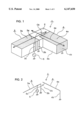
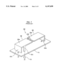
- FIG. 1 is a perspective view of an antenna device according to a first preferred embodiment of the present invention.
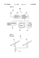
- FIG. 2 is a schematic view of the antenna device of FIG. 1.
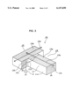
- FIG. 3 is a perspective view of an antenna device according to a second preferred embodiment of the present invention.
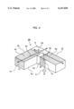
- FIG. 4 is a perspective view of an antenna device according to a third preferred embodiment of the present invention.
- FIG. 5 is a block diagram of a radio device according to a fourth preferred embodiment of the present invention.
- FIG. 6 is a perspective view of an antenna device which is a prior art of the present invention.
- FIG. 7 is a perspective view of another antenna device which is a prior art of the present invention.
- FIG. 1 shows an antenna device according to a first preferred embodiment of the present invention.
- the antenna device 1 of FIG. 1 comprises a substrate 2 made of an insulation material, namely, a dielectric, and having a L-shape, a ground electrode 2a provided substantially on the whole of a first major surface of the substrate 2, and an inverted F-shape antenna 3 and a microstrip antenna 4 provided in the second major surface and a side surface of the substrate 2.
- the inverted F-shape antenna 3 is made up of a first radiation electrode 3a formed in one of the linear portions which constitute the L-shaped second major surface of the substrate 2, a first connecting electrode 3b which is formed in one side surface of the substrate 2 and connects the other end of the first radiation electrode 3a to the ground electrode 2a whereby the other end of the first radiation electrode 3a functions as a ground end, and a feeding electrode 3c provided in the vicinity of the ground end of the first radiation electrode 3a and having one end connected to the first radiation electrode 3a.
- the one end of the first radiation electrode 3a is open.
- the length between the one end and the other end of the first radiation electrode 3a is substantially equal to a quarter-wavelength.
- the other end of the feeding electrode 3c is connected to a signal supply 5 and insulated from the ground electrode 2a.
- the microstrip antenna 4 is made up of a second radiation electrode 4a formed in the other of the linear portions which constitute the L-shaped second major surface of the substrate 2, and a second connecting electrode 4b which is formed in one side surface of the substrate 2 and connects the other end of the second radiation electrode 4a to the ground electrode 2a whereby the other end of the second radiation electrode 4a functions as a ground end.
- the one end of the second radiation electrode 4a is open.
- the length between the one end and the other end of the second radiation electrode 4a is substantially equal to a quarter-wavelength.
- the open end of the second radiation electrode 4a of the microstrip antenna 4 is positioned near to the feeding electrode 3c of the inverted F-shape antenna 3, and a static capacitance C4 is produced between them.
- the inverted F-shape antenna 3 and the microstrip antenna 4 are so arranged that directions 3x and 4x through the open ends and the ground ends of the first and second radiation electrodes 3a and 4a, respectively, are substantially perpendicular to each other.
- the inverted F-shape antenna 3 and the microstrip antenna 4 are so set that the frequency bands of them are different from each other.
- a signal, output from the signal supply 5, is applied to the inverted F-shape antenna 3 through the feeding electrode 3c, and is also applied to the microstrip antenna 4 through the static capacitance C4 produced between the feeding electrode 3c and the open end of the second radiation electrode 4a.
- the first radiation electrode 3a of the inverted F-shape antenna 3 and the second radiation electrode 4a of the microstrip antenna 4 resonate at the quarter-wavelengths of the frequencies of the signal which is applied to the first radiation electrode 3a and the second radiation electrode 4a, respectively. That is, they are operated as antennas, so that radio waves are transmitted or received according to the respective frequency bands of the antennas.
- Japanese Unexamined Patent Publication No. 9-98015 discloses an antenna in which a signal is applied to a radiation electrode through a static capacitance produced between a feeding electrode and the open end of a microstrip radiation electrode.
- the antenna device 1 Ordinarily, two antennas, if they are arranged near to each other, can not satisfactorily perform their functions, respectively, because of their mutual interference.
- the first and second radiation electrodes are so arranged that the directions 3x and 4x through the open ends and the ground ends of the first and second radiation electrodes of the two antennas, respectively, are substantially perpendicular to each other. Therefore, the polarized wave planes of radio waves radiated from the two antennas are substantially perpendicular to each other, hardly causing the mutual interference between the two antennas.
- the antenna device 1 though it is miniaturized by positioning the two antennas near to each other, can be operated as an antenna adapted to use with the two frequency bands without problems of the mutual interference.
- FIG. 2 schematically shows the antenna device 1 of FIG. 1.
- the first and second radiation electrodes 3a and 4a of the inverted F-shape antenna 3 and the microstrip antenna 4 shown in FIG. 1 are illustrated respectively in the form of a single line.
- These single-lines for the two radiation electrodes correspond to the directions 3x and 4x through the open ends and the ground ends of the two antennas, respectively.
- the radiation electrodes of the inverted F-shape antenna and the microstrip antenna are not restricted on the rectangular shapes as shown in FIG. 1.
- the radiation electrodes may have any shape, for examples, a trapezoidal or triangular shape, provided that the directions through the open ends and the ground ends of the radiation electrodes of the two antennas, respectively, are substantially perpendicular to each other, as shown in FIG. 2.
- the guide wavelengths of a signal in the two antennas can be shortened by forming the inverted F-shape antenna 3 and the microstrip antenna 4 on the substrate 2 made of a dielectric. Accordingly, the sizes of the two antennas can be reduced. As a result, the antenna device 1 can be miniaturized. Especially, this effect can be enhanced by employing for the substrate a dielectric having a high permittivity.
- the radiation electrodes are so formed as to adhere closely to the substrate. This is effective in preventing the radiation electrodes from being vibrated so that the characteristics are varied, which may be caused by an external vibration and the like.
- the two antennas i.e., the inverted F-shape antenna 3 and the microstrip antenna 4 are provided on the single substrate 2, the process for adjusting the directions of the two antennas is unnecessary, in contrast to the use of two separate antennas for formation of an antenna device. Assembly of the antenna device and mounting thereof on a printed circuit board can be easily achieved.
- FIG. 3 shows an antenna device according to a second preferred embodiment of the present invention.
- the antenna device 10 shown in FIG. 3 comprises a substrate 11 made of an insulation material, that is, a dielectric and having a T-shape, a ground electrode 11a formed substantially on the whole of a first major surface of the substrate 11, and an inverted F-shape antenna 12 and a micronstrip antenna 13 provided on a second major surface and a side surface of the substrate 11.
- the inverted F-shape antenna 12 is made up of a first radiation electrode 12a formed on one linear portion of the T-shaped second major surface of the substrate 11, a first connecting electrode 12b which is provided in one side surface of the substrate 11 and connects the other end of the first radiation electrode 12a to the ground electrode 11a whereby the other end of the first radiation electrode 12a functions as a ground end, and a feeding electrode 12c formed in the vicinity of the ground end of the first radiation electrode 12a and having one end connected to the first radiation electrode 12a.
- One end of the first radiation electrode 12a is open.
- the length from the one end to the other end of the first radiation electrode 12a is substantially equal to a quarter-wavelength.
- the other end of the feeding electrode 12c is connected to the signal supply 5 and insulated from the connecting electrode 11a.
- the micronstrip antenna 13 is made up of a second radiation electrode 13a formed on the other linear portion of the T-shaped second major surface of the substrate 11, and a second electrode 13b provided on one side surface of the substrate 11 and connecting the other end of the second radiation electrode 13a to the ground electrode 11a.
- the one end of the second radiation electrode 13a is open.
- the length from the open end to the other end of the second radiation electrode 13a is substantially equal to a quarter-wavelength.
- the open end of the second radiation electrode 13a of the micronstrip antenna 13 is arranged near to the feeding electrode 12c of the inverted F-shape antenna 12, and a static capacitance C13 is produced between them. Furthermore, the first and second radiation electrodes 12a and 13a of the inverted F-shape antenna 12 and the microstrip antenna 13 are so arranged that directions 12x and 13x through their open ends and ground ends, respectively, are substantially perpendicular to each other. Moreover, the inverted F-shape antenna 12 and the micronstrip antenna 13 are so set that their frequency bands are different.
- the antenna device 10 configured as described above can be operated as an antenna adapted to use with two frequency bands, as well as the antenna device 1. With the antenna device 10, operation and advantages similar to those of the antenna device 1 can be obtained.
- the substrates have L- and T-shapes, respectively.
- the substrates are not restricted on these shapes and may take another shape such as a prism shape, a dougnut-shape, and the like.
- the dielectric is used as an insulation material for the substrate.
- a magnetic material may be employed as the material for the substrate.
- the inverted F-shape antenna and the microstrip antenna of which the frequency bands are set different are described.
- the frequency bands of the two antennas may be overlapped or made to coincide with each other.
- the antenna device in which the frequency bands of the two antennas are substantially coincident with each other will be described below in reference to the antenna device 1, as an example, shown in FIG. 1, which is adapted for use with a circularly polarized wave.
- the inverted F-shape antenna 2 and the microstrip antenna 3 shown in FIG. 1 are so set that their frequency bands are substantially coincident with each other.
- a current is supplied directly to the inverted F-shape antenna 2 through the feeding electrode 2c and to the microstrip antenna 3 through the feeding electrode 3c and then the static capacitance C4. Therefore, in the two antennas, a resonant phase difference is presented with a signal having the same frequency.
- the resonant phase difference at the same frequency of the inverted F-shape antenna 2 and the microstrip antenna 3 can be set at 90°0 by properly setting the resonant frequencies of the inverted F-shape antenna 2 and the microstrip antenna 3 and the static capacitance C4.
- the antenna device 1 by so arranging the inverted F-shape antenna 2 and the microstrip antenna 3 that the directions 3x and 4x through the open ends and the ground ends of the first and second radiation electrodes 2a and 3a are substantially perpendicular to each other, whereby the circularly polarized wave planes of the two antennas are perpendicular to each other, and moreover, setting the resonant phase difference of the two antennas at 90°, the antenna device 1 can be operated as a circularly polarized wave antenna.
- the circularly polarized wave is a fixed wave, that is, a right-handed or left-handed polarized wave.
- the rotation direction of the circularly polarized wave can be reversed by changing the position of the microstrip antenna 4 with respect to the inverted F-shape antenna 3.
- the positional relation between the inverted F-shape antenna 3 and the microstrip antenna 4 is merely changed.
- FIGS. 1 and 4 are designated by the same reference numerals. The description of the parts in reference to FIG. 4 is omitted.
- a fourth preferred embodiment of the present invention shown in FIG. 5. is a navigation system including a radio device of the present invention which utilizes the circularly polarized wave.
- a radio device 30 comprises an antenna section 31 which is the antenna device 1 of the present invention configured as a circularly polarized wave antenna, provided with a radome and accommodated in a case, a receiving section 32 connected to the antenna section 31, a signal processing section 33 connected to the receiving section 32, and a map system 34, a display 35, and an interface section 36 connected to the signal processing section 33, respectively.
- the antenna section 31 receives radio waves from plural GPS satellites.
- the receiving section 32 picks up various signals from the radio waves.
- the signal processing section 33 determines the present location of the radio device 30 itself, that is, that of a motorcar in which the radio device 30 is mounted, and indicates the location on the display 35 in cooperation with the map system 34 having a map software in the form of CD-ROM and the like, and the interface section 36 such as a remote control device and the like.
- the radio device itself can be miniaturized, and its cost saving can be achieved.
- the design flexibility of the space where the antenna is to be placed is increased, and thereby, the cost of the installation of the navigation system, for example, in a motorcar can be reduced.
- the radio device 34 is constructed by use of the antenna device 1, as described above. Radio devices configured by using the antenna devices 10 and 20 shown in FIGS. 3 and 4, respectively also present similar operation and advantages.
Landscapes
- Waveguide Aerials (AREA)
- Details Of Aerials (AREA)
- Variable-Direction Aerials And Aerial Arrays (AREA)
Applications Claiming Priority (4)
| Application Number | Priority Date | Filing Date | Title |
|---|---|---|---|
| JP4195598 | 1998-02-24 | ||
| JP10-041955 | 1998-02-24 | ||
| JP06145798A JP3252786B2 (ja) | 1998-02-24 | 1998-03-12 | アンテナ装置およびそれを用いた無線装置 |
| JP10-061457 | 1998-03-12 |
Publications (1)
| Publication Number | Publication Date |
|---|---|
| US6147650A true US6147650A (en) | 2000-11-14 |
Family
ID=26381606
Family Applications (1)
| Application Number | Title | Priority Date | Filing Date |
|---|---|---|---|
| US09/252,443 Expired - Lifetime US6147650A (en) | 1998-02-24 | 1999-02-18 | Antenna device and radio device comprising the same |
Country Status (4)
| Country | Link |
|---|---|
| US (1) | US6147650A (fr) |
| EP (1) | EP0942488B1 (fr) |
| JP (1) | JP3252786B2 (fr) |
| DE (1) | DE69920084T2 (fr) |
Cited By (60)
| Publication number | Priority date | Publication date | Assignee | Title |
|---|---|---|---|---|
| US6281848B1 (en) * | 1999-06-25 | 2001-08-28 | Murata Manufacturing Co., Ltd. | Antenna device and communication apparatus using the same |
| US6323811B1 (en) * | 1999-09-30 | 2001-11-27 | Murata Manufacturing Co., Ltd. | Surface-mount antenna and communication device with surface-mount antenna |
| US6419506B2 (en) * | 2000-01-20 | 2002-07-16 | 3Com Corporation | Combination miniature cable connector and antenna |
| US6448932B1 (en) * | 2001-09-04 | 2002-09-10 | Centurion Wireless Technologies, Inc. | Dual feed internal antenna |
| US6452548B2 (en) * | 2000-02-04 | 2002-09-17 | Murata Manufacturing Co., Ltd. | Surface mount antenna and communication device including the same |
| US20030006936A1 (en) * | 2001-06-15 | 2003-01-09 | Hitachi Metals, Ltd. | Surface-mounted antenna and communications apparatus comprising same |
| US6507318B2 (en) * | 2000-03-09 | 2003-01-14 | Sony Corporation | Antenna apparatus and portable communication apparatus |
| KR20030030843A (ko) * | 2001-10-12 | 2003-04-18 | 삼성전자주식회사 | 휴대통신기기용 안테나 |
| US20030181227A1 (en) * | 2002-02-28 | 2003-09-25 | Kabushiki Kaisha Toshiba | Electronic device and antenna mounting method |
| US20040227675A1 (en) * | 2003-02-25 | 2004-11-18 | Nec Corporation | Antenna apparatus having high receiving efficiency |
| US20070120740A1 (en) * | 2003-12-12 | 2007-05-31 | Devis Iellici | Antenna for mobile telephone handsets, pdas, and the like |
| US20070152885A1 (en) * | 2004-06-28 | 2007-07-05 | Juha Sorvala | Chip antenna apparatus and methods |
| US20070171131A1 (en) * | 2004-06-28 | 2007-07-26 | Juha Sorvala | Antenna, component and methods |
| US20080007459A1 (en) * | 2004-11-11 | 2008-01-10 | Kimmo Koskiniemi | Antenna component and methods |
| US20080015631A1 (en) * | 2006-07-11 | 2008-01-17 | Woojin Lee | Surgical instrument |
| US20080204328A1 (en) * | 2007-09-28 | 2008-08-28 | Pertti Nissinen | Dual antenna apparatus and methods |
| US7427955B2 (en) * | 2004-12-08 | 2008-09-23 | Electronics And Telecommunications Research Institute | Dual polarization antenna and RFID reader employing the same |
| US20090135066A1 (en) * | 2005-02-08 | 2009-05-28 | Ari Raappana | Internal Monopole Antenna |
| US20090231201A1 (en) * | 2006-05-26 | 2009-09-17 | Petteri Annamaa | Dual Antenna and Methods |
| US20110050540A1 (en) * | 2006-01-13 | 2011-03-03 | Research In Motion Limited | Mobile wireless communications device including an electrically conductive director element and related methods |
| US7903035B2 (en) | 2005-10-10 | 2011-03-08 | Pulse Finland Oy | Internal antenna and methods |
| US8105350B2 (en) | 2006-05-23 | 2012-01-31 | Cambridge Endoscopic Devices, Inc. | Surgical instrument |
| US8378892B2 (en) | 2005-03-16 | 2013-02-19 | Pulse Finland Oy | Antenna component and methods |
| US8466756B2 (en) | 2007-04-19 | 2013-06-18 | Pulse Finland Oy | Methods and apparatus for matching an antenna |
| US8473017B2 (en) | 2005-10-14 | 2013-06-25 | Pulse Finland Oy | Adjustable antenna and methods |
| US8564485B2 (en) | 2005-07-25 | 2013-10-22 | Pulse Finland Oy | Adjustable multiband antenna and methods |
| US8618990B2 (en) | 2011-04-13 | 2013-12-31 | Pulse Finland Oy | Wideband antenna and methods |
| US8629813B2 (en) | 2007-08-30 | 2014-01-14 | Pusle Finland Oy | Adjustable multi-band antenna and methods |
| US20140028519A1 (en) * | 2012-07-27 | 2014-01-30 | Ls Mtron Ltd. | Internal antenna having wideband characteristic |
| US8648752B2 (en) | 2011-02-11 | 2014-02-11 | Pulse Finland Oy | Chassis-excited antenna apparatus and methods |
| US20140078017A1 (en) * | 2012-09-18 | 2014-03-20 | Futurewei Technologies, Inc. | Multi Layer 3D Antenna Carrier Arrangement for Electronic Devices |
| US8786499B2 (en) | 2005-10-03 | 2014-07-22 | Pulse Finland Oy | Multiband antenna system and methods |
| US8847833B2 (en) | 2009-12-29 | 2014-09-30 | Pulse Finland Oy | Loop resonator apparatus and methods for enhanced field control |
| US8866689B2 (en) | 2011-07-07 | 2014-10-21 | Pulse Finland Oy | Multi-band antenna and methods for long term evolution wireless system |
| US8988296B2 (en) | 2012-04-04 | 2015-03-24 | Pulse Finland Oy | Compact polarized antenna and methods |
| US9123990B2 (en) | 2011-10-07 | 2015-09-01 | Pulse Finland Oy | Multi-feed antenna apparatus and methods |
| US9203154B2 (en) | 2011-01-25 | 2015-12-01 | Pulse Finland Oy | Multi-resonance antenna, antenna module, radio device and methods |
| US9246210B2 (en) | 2010-02-18 | 2016-01-26 | Pulse Finland Oy | Antenna with cover radiator and methods |
| US9350081B2 (en) | 2014-01-14 | 2016-05-24 | Pulse Finland Oy | Switchable multi-radiator high band antenna apparatus |
| US9406998B2 (en) | 2010-04-21 | 2016-08-02 | Pulse Finland Oy | Distributed multiband antenna and methods |
| US9450291B2 (en) | 2011-07-25 | 2016-09-20 | Pulse Finland Oy | Multiband slot loop antenna apparatus and methods |
| US9461371B2 (en) | 2009-11-27 | 2016-10-04 | Pulse Finland Oy | MIMO antenna and methods |
| US9484619B2 (en) | 2011-12-21 | 2016-11-01 | Pulse Finland Oy | Switchable diversity antenna apparatus and methods |
| US9531058B2 (en) | 2011-12-20 | 2016-12-27 | Pulse Finland Oy | Loosely-coupled radio antenna apparatus and methods |
| US9590308B2 (en) | 2013-12-03 | 2017-03-07 | Pulse Electronics, Inc. | Reduced surface area antenna apparatus and mobile communications devices incorporating the same |
| US9634383B2 (en) | 2013-06-26 | 2017-04-25 | Pulse Finland Oy | Galvanically separated non-interacting antenna sector apparatus and methods |
| US9647338B2 (en) | 2013-03-11 | 2017-05-09 | Pulse Finland Oy | Coupled antenna structure and methods |
| US9673507B2 (en) | 2011-02-11 | 2017-06-06 | Pulse Finland Oy | Chassis-excited antenna apparatus and methods |
| US9680212B2 (en) | 2013-11-20 | 2017-06-13 | Pulse Finland Oy | Capacitive grounding methods and apparatus for mobile devices |
| US9722308B2 (en) | 2014-08-28 | 2017-08-01 | Pulse Finland Oy | Low passive intermodulation distributed antenna system for multiple-input multiple-output systems and methods of use |
| US9761951B2 (en) | 2009-11-03 | 2017-09-12 | Pulse Finland Oy | Adjustable antenna apparatus and methods |
| US9906260B2 (en) | 2015-07-30 | 2018-02-27 | Pulse Finland Oy | Sensor-based closed loop antenna swapping apparatus and methods |
| US9948002B2 (en) | 2014-08-26 | 2018-04-17 | Pulse Finland Oy | Antenna apparatus with an integrated proximity sensor and methods |
| US9973228B2 (en) | 2014-08-26 | 2018-05-15 | Pulse Finland Oy | Antenna apparatus with an integrated proximity sensor and methods |
| US9979078B2 (en) | 2012-10-25 | 2018-05-22 | Pulse Finland Oy | Modular cell antenna apparatus and methods |
| US10069209B2 (en) | 2012-11-06 | 2018-09-04 | Pulse Finland Oy | Capacitively coupled antenna apparatus and methods |
| US10079428B2 (en) | 2013-03-11 | 2018-09-18 | Pulse Finland Oy | Coupled antenna structure and methods |
| US10211538B2 (en) | 2006-12-28 | 2019-02-19 | Pulse Finland Oy | Directional antenna apparatus and methods |
| US20240170845A1 (en) * | 2021-03-25 | 2024-05-23 | Yokowo Co., Ltd. | Antenna device |
| EP4160821A4 (fr) * | 2020-05-28 | 2024-10-30 | Guangdong Genius Technology Co., Ltd. | Antenne de positionnement à polarisation circulaire à fréquence unique et dispositif habitronique |
Families Citing this family (67)
| Publication number | Priority date | Publication date | Assignee | Title |
|---|---|---|---|---|
| DE69941025D1 (de) * | 1999-07-09 | 2009-08-06 | Ipcom Gmbh & Co Kg | Zweibandfunkgerät |
| DE60033275T2 (de) * | 1999-09-09 | 2007-10-25 | Murata Manufacturing Co., Ltd., Nagaokakyo | Oberflächenmontierbare antenne und kommunikationsgerät mit einer derartigen antenne |
| EP1223637B1 (fr) | 1999-09-20 | 2005-03-30 | Fractus, S.A. | Antennes multiniveau |
| JP4263820B2 (ja) * | 1999-10-21 | 2009-05-13 | 株式会社ヨコオ | 円偏波用平面アンテナ |
| MXPA02004221A (es) | 1999-10-26 | 2003-08-20 | Fractus Sa | Agrupaciones multibanda de antenas entrelazadas. |
| JP3646782B2 (ja) * | 1999-12-14 | 2005-05-11 | 株式会社村田製作所 | アンテナ装置およびそれを用いた通信機 |
| US6480155B1 (en) | 1999-12-28 | 2002-11-12 | Nokia Corporation | Antenna assembly, and associated method, having an active antenna element and counter antenna element |
| EP1592083B1 (fr) | 2000-01-19 | 2013-04-03 | Fractus, S.A. | antennes miniatures de remplissage d'espace |
| SE516293C2 (sv) * | 2000-03-02 | 2001-12-17 | Allgon Ab | En bredbandig, intern antennanordning för multipla band och en bärbar radiokommunikationsanordning innefattande en sådan antennanordning. |
| FI112724B (fi) * | 2000-05-12 | 2003-12-31 | Nokia Corp | Symmetrinen antennirakenne ja menetelmä sen valmistamiseksi sekä antennirakennetta soveltava laajennuskortti |
| JP3640595B2 (ja) * | 2000-05-18 | 2005-04-20 | シャープ株式会社 | 積層パターンアンテナ及びそれを備えた無線通信装置 |
| WO2001091233A1 (fr) * | 2000-05-23 | 2001-11-29 | Telefonaktiebolaget Lm Ericsson (Publ) | Antenne multibande |
| DE60033140T2 (de) * | 2000-05-23 | 2007-10-31 | Telefonaktiebolaget Lm Ericsson (Publ) | Mehrfrequenzband-Antenne |
| DE10039772A1 (de) * | 2000-08-16 | 2002-03-07 | Bosch Gmbh Robert | Kombinationsantenne |
| AU2001280076B2 (en) * | 2000-08-28 | 2007-04-05 | In4Tel Ltd. | Apparatus and method for enhancing low-frequency operation of mobile communication antennas |
| US7511675B2 (en) | 2000-10-26 | 2009-03-31 | Advanced Automotive Antennas, S.L. | Antenna system for a motor vehicle |
| US7102575B2 (en) | 2000-11-24 | 2006-09-05 | Siemens Aktiengesellschaft | PIFA antenna apparatus for mobile communications terminals |
| CN2476881Y (zh) * | 2000-12-30 | 2002-02-13 | 深圳市中兴通讯股份有限公司 | 一种手机内置式平面天线 |
| WO2002063719A1 (fr) * | 2001-02-05 | 2002-08-15 | Sony Corporation | Petite antenne basse et son mode de realisation |
| KR20030080217A (ko) | 2001-02-07 | 2003-10-11 | 프레이투스, 에스.에이. | 소형 광대역 고리형 마이크로스트립 패치 안테나 |
| KR20030085000A (ko) | 2001-03-22 | 2003-11-01 | 텔레폰악티에볼라겟엘엠에릭슨(펍) | 이동 통신 장치 |
| DE60128837T2 (de) | 2001-04-16 | 2008-02-28 | Fractus, S.A. | Doppelbandige dualpolarisierte gruppenantenne |
| US6686886B2 (en) * | 2001-05-29 | 2004-02-03 | International Business Machines Corporation | Integrated antenna for laptop applications |
| US7339531B2 (en) | 2001-06-26 | 2008-03-04 | Ethertronics, Inc. | Multi frequency magnetic dipole antenna structures and method of reusing the volume of an antenna |
| US6906667B1 (en) | 2002-02-14 | 2005-06-14 | Ethertronics, Inc. | Multi frequency magnetic dipole antenna structures for very low-profile antenna applications |
| US6456243B1 (en) | 2001-06-26 | 2002-09-24 | Ethertronics, Inc. | Multi frequency magnetic dipole antenna structures and methods of reusing the volume of an antenna |
| US9755314B2 (en) | 2001-10-16 | 2017-09-05 | Fractus S.A. | Loaded antenna |
| EP1436858A1 (fr) * | 2001-10-16 | 2004-07-14 | Fractus, S.A. | Antenne multibande |
| WO2003034545A1 (fr) | 2001-10-16 | 2003-04-24 | Fractus, S.A. | Antenne a plaque microruban multifrequence avec elements couples non alimentes |
| CN100382385C (zh) | 2001-10-16 | 2008-04-16 | 弗拉克托斯股份有限公司 | 加载天线 |
| DE10204079A1 (de) * | 2002-02-01 | 2003-08-21 | Imst Gmbh | Mehrbandantenne mit parasitären Strahlern |
| US20040239564A1 (en) * | 2002-03-28 | 2004-12-02 | Misako Sakae | Antenna and electronic apparatus using it |
| WO2003092118A1 (fr) | 2002-04-25 | 2003-11-06 | Ethertronics, Inc. | Antennes dipoles magnetiques a charge capacitive discretes, multibandes, multifrequences |
| US6717551B1 (en) | 2002-11-12 | 2004-04-06 | Ethertronics, Inc. | Low-profile, multi-frequency, multi-band, magnetic dipole antenna |
| US6943730B2 (en) | 2002-04-25 | 2005-09-13 | Ethertronics Inc. | Low-profile, multi-frequency, multi-band, capacitively loaded magnetic dipole antenna |
| US6744410B2 (en) | 2002-05-31 | 2004-06-01 | Ethertronics, Inc. | Multi-band, low-profile, capacitively loaded antennas with integrated filters |
| JP3794360B2 (ja) * | 2002-08-23 | 2006-07-05 | 株式会社村田製作所 | アンテナ構造およびそれを備えた通信機 |
| AU2002333900A1 (en) | 2002-09-10 | 2004-04-30 | Fractus, S.A. | Coupled multiband antennas |
| US6911940B2 (en) | 2002-11-18 | 2005-06-28 | Ethertronics, Inc. | Multi-band reconfigurable capacitively loaded magnetic dipole |
| US6859175B2 (en) | 2002-12-03 | 2005-02-22 | Ethertronics, Inc. | Multiple frequency antennas with reduced space and relative assembly |
| US7084813B2 (en) | 2002-12-17 | 2006-08-01 | Ethertronics, Inc. | Antennas with reduced space and improved performance |
| US20060066488A1 (en) * | 2003-01-17 | 2006-03-30 | Ying Zhinong | Antenna |
| EP1443595A1 (fr) * | 2003-01-17 | 2004-08-04 | Sony Ericsson Mobile Communications AB | Antenne |
| US6919857B2 (en) | 2003-01-27 | 2005-07-19 | Ethertronics, Inc. | Differential mode capacitively loaded magnetic dipole antenna |
| WO2004070872A1 (fr) * | 2003-02-04 | 2004-08-19 | Philips Intellectual Property & Standards Gmbh | Antenne plane haute-frequence ou micro-ondes |
| US7123209B1 (en) | 2003-02-26 | 2006-10-17 | Ethertronics, Inc. | Low-profile, multi-frequency, differential antenna structures |
| GB0318667D0 (en) * | 2003-08-08 | 2003-09-10 | Antenova Ltd | Antennas for wireless communication to a laptop computer |
| JP2005064938A (ja) | 2003-08-14 | 2005-03-10 | Nec Access Technica Ltd | 小型無線機用アンテナ装置 |
| JP2006295876A (ja) * | 2005-03-15 | 2006-10-26 | Matsushita Electric Ind Co Ltd | アンテナ装置およびそれを用いた無線通信機 |
| KR100689475B1 (ko) | 2005-04-27 | 2007-03-02 | 삼성전자주식회사 | 휴대 단말기의 내장형 안테나 장치 |
| FI20055353A0 (fi) * | 2005-06-28 | 2005-06-28 | Lk Products Oy | Sisäinen monikaista-antenni |
| JP4690820B2 (ja) * | 2005-08-08 | 2011-06-01 | 古河電気工業株式会社 | アンテナ装置 |
| JP4227141B2 (ja) * | 2006-02-10 | 2009-02-18 | 株式会社カシオ日立モバイルコミュニケーションズ | アンテナ装置 |
| US8738103B2 (en) | 2006-07-18 | 2014-05-27 | Fractus, S.A. | Multiple-body-configuration multimedia and smartphone multifunction wireless devices |
| KR100814432B1 (ko) | 2006-08-29 | 2008-03-18 | 삼성전자주식회사 | Sar이 감소된 이중대역 역 f안테나 |
| JP2008060762A (ja) * | 2006-08-30 | 2008-03-13 | Yokowo Co Ltd | アンテナの給電構造 |
| KR101464510B1 (ko) * | 2007-10-17 | 2014-11-26 | 삼성전자주식회사 | Mimo 안테나 장치 |
| US7768463B2 (en) * | 2008-04-16 | 2010-08-03 | Sony Ericsson Mobile Communications Ab | Antenna assembly, printed wiring board and device |
| US7821470B2 (en) * | 2008-07-18 | 2010-10-26 | Sony Ericsson Mobile Communications Ab | Antenna arrangement |
| FI20085907A7 (fi) * | 2008-09-25 | 2010-03-26 | Pulse Finland Oy | Antenniyhdistelmä |
| JP2010171507A (ja) * | 2009-01-20 | 2010-08-05 | Furukawa Electric Co Ltd:The | 車載用複合アンテナ |
| US8390520B2 (en) | 2010-03-11 | 2013-03-05 | Raytheon Company | Dual-patch antenna and array |
| GB201100617D0 (en) | 2011-01-14 | 2011-03-02 | Antenova Ltd | Dual antenna structure having circular polarisation characteristics |
| JP5703977B2 (ja) * | 2011-06-07 | 2015-04-22 | 株式会社村田製作所 | 無線通信デバイス付き金属物品 |
| JP6930444B2 (ja) * | 2018-01-29 | 2021-09-01 | 三菱マテリアル株式会社 | アンテナ装置 |
| JP6998086B2 (ja) * | 2018-05-24 | 2022-01-18 | 株式会社フェニックスソリューション | Rfタグアンテナ、rfタグおよび導電体付きrfタグ |
| CN114389005B (zh) * | 2020-10-19 | 2023-07-28 | 华为技术有限公司 | 一种电子设备 |
Citations (6)
| Publication number | Priority date | Publication date | Assignee | Title |
|---|---|---|---|---|
| GB2067842A (en) * | 1980-01-16 | 1981-07-30 | Secr Defence | Microstrip Antenna |
| WO1991002386A1 (fr) * | 1989-07-27 | 1991-02-21 | SIEMENS AKTIENGESELLSCHAFT öSTERREICH | Dispositif d'emission et de reception pour appareils portatifs |
| GB2238665A (en) * | 1989-11-27 | 1991-06-05 | Kokusai Denshin Denwa Co Ltd | Microstrip antenna |
| EP0655797A1 (fr) * | 1993-11-26 | 1995-05-31 | Motorola, Inc. | Antenne microbande accordable avec un accouplement à fente quart d'onde |
| EP0790668A2 (fr) * | 1996-02-19 | 1997-08-20 | Murata Manufacturing Co., Ltd. | Antenne et appareil de communication utilisant une telle antenne |
| FR2749438A1 (fr) * | 1996-06-03 | 1997-12-05 | Mitsubishi Electric Corp | Dispositif d'antenne |
Family Cites Families (3)
| Publication number | Priority date | Publication date | Assignee | Title |
|---|---|---|---|---|
| JP3185856B2 (ja) * | 1995-11-29 | 2001-07-11 | 株式会社エヌ・ティ・ティ・ドコモ | 二周波共振アンテナ装置 |
| JP3139610B2 (ja) * | 1995-12-04 | 2001-03-05 | 株式会社エヌ・ティ・ティ・ドコモ | マイクロストリップアンテナ装置 |
| JPH1093332A (ja) * | 1996-09-13 | 1998-04-10 | Nippon Antenna Co Ltd | 複共振逆f型アンテナ |
-
1998
- 1998-03-12 JP JP06145798A patent/JP3252786B2/ja not_active Expired - Fee Related
-
1999
- 1999-02-18 DE DE69920084T patent/DE69920084T2/de not_active Expired - Lifetime
- 1999-02-18 EP EP99103211A patent/EP0942488B1/fr not_active Expired - Lifetime
- 1999-02-18 US US09/252,443 patent/US6147650A/en not_active Expired - Lifetime
Patent Citations (8)
| Publication number | Priority date | Publication date | Assignee | Title |
|---|---|---|---|---|
| GB2067842A (en) * | 1980-01-16 | 1981-07-30 | Secr Defence | Microstrip Antenna |
| WO1991002386A1 (fr) * | 1989-07-27 | 1991-02-21 | SIEMENS AKTIENGESELLSCHAFT öSTERREICH | Dispositif d'emission et de reception pour appareils portatifs |
| US5365246A (en) * | 1989-07-27 | 1994-11-15 | Siemens Aktiengesellschaft | Transmitting and/or receiving arrangement for portable appliances |
| GB2238665A (en) * | 1989-11-27 | 1991-06-05 | Kokusai Denshin Denwa Co Ltd | Microstrip antenna |
| EP0655797A1 (fr) * | 1993-11-26 | 1995-05-31 | Motorola, Inc. | Antenne microbande accordable avec un accouplement à fente quart d'onde |
| EP0790668A2 (fr) * | 1996-02-19 | 1997-08-20 | Murata Manufacturing Co., Ltd. | Antenne et appareil de communication utilisant une telle antenne |
| FR2749438A1 (fr) * | 1996-06-03 | 1997-12-05 | Mitsubishi Electric Corp | Dispositif d'antenne |
| US5966097A (en) * | 1996-06-03 | 1999-10-12 | Mitsubishi Denki Kabushiki Kaisha | Antenna apparatus |
Cited By (81)
| Publication number | Priority date | Publication date | Assignee | Title |
|---|---|---|---|---|
| US6281848B1 (en) * | 1999-06-25 | 2001-08-28 | Murata Manufacturing Co., Ltd. | Antenna device and communication apparatus using the same |
| US6323811B1 (en) * | 1999-09-30 | 2001-11-27 | Murata Manufacturing Co., Ltd. | Surface-mount antenna and communication device with surface-mount antenna |
| US6419506B2 (en) * | 2000-01-20 | 2002-07-16 | 3Com Corporation | Combination miniature cable connector and antenna |
| US6452548B2 (en) * | 2000-02-04 | 2002-09-17 | Murata Manufacturing Co., Ltd. | Surface mount antenna and communication device including the same |
| US6507318B2 (en) * | 2000-03-09 | 2003-01-14 | Sony Corporation | Antenna apparatus and portable communication apparatus |
| US6873291B2 (en) * | 2001-06-15 | 2005-03-29 | Hitachi Metals, Ltd. | Surface-mounted antenna and communications apparatus comprising same |
| CN100388829C (zh) * | 2001-06-15 | 2008-05-14 | 日立金属株式会社 | 表面安装型天线及搭载这种天线的通信装置 |
| US20030006936A1 (en) * | 2001-06-15 | 2003-01-09 | Hitachi Metals, Ltd. | Surface-mounted antenna and communications apparatus comprising same |
| US6448932B1 (en) * | 2001-09-04 | 2002-09-10 | Centurion Wireless Technologies, Inc. | Dual feed internal antenna |
| KR20030030843A (ko) * | 2001-10-12 | 2003-04-18 | 삼성전자주식회사 | 휴대통신기기용 안테나 |
| US20030181227A1 (en) * | 2002-02-28 | 2003-09-25 | Kabushiki Kaisha Toshiba | Electronic device and antenna mounting method |
| US20040227675A1 (en) * | 2003-02-25 | 2004-11-18 | Nec Corporation | Antenna apparatus having high receiving efficiency |
| US7026996B2 (en) * | 2003-02-25 | 2006-04-11 | Nec Corporation | Antenna apparatus having high receiving efficiency |
| US20070120740A1 (en) * | 2003-12-12 | 2007-05-31 | Devis Iellici | Antenna for mobile telephone handsets, pdas, and the like |
| US7705786B2 (en) * | 2003-12-12 | 2010-04-27 | Antenova Ltd. | Antenna for mobile telephone handsets, PDAs, and the like |
| US20100176998A1 (en) * | 2004-06-28 | 2010-07-15 | Juha Sorvala | Chip antenna apparatus and methods |
| US8004470B2 (en) | 2004-06-28 | 2011-08-23 | Pulse Finland Oy | Antenna, component and methods |
| US20070171131A1 (en) * | 2004-06-28 | 2007-07-26 | Juha Sorvala | Antenna, component and methods |
| US7679565B2 (en) | 2004-06-28 | 2010-03-16 | Pulse Finland Oy | Chip antenna apparatus and methods |
| US20070152885A1 (en) * | 2004-06-28 | 2007-07-05 | Juha Sorvala | Chip antenna apparatus and methods |
| US7973720B2 (en) | 2004-06-28 | 2011-07-05 | LKP Pulse Finland OY | Chip antenna apparatus and methods |
| US7786938B2 (en) | 2004-06-28 | 2010-08-31 | Pulse Finland Oy | Antenna, component and methods |
| US20100321250A1 (en) * | 2004-06-28 | 2010-12-23 | Juha Sorvala | Antenna, Component and Methods |
| US8390522B2 (en) | 2004-06-28 | 2013-03-05 | Pulse Finland Oy | Antenna, component and methods |
| US7916086B2 (en) | 2004-11-11 | 2011-03-29 | Pulse Finland Oy | Antenna component and methods |
| US20080007459A1 (en) * | 2004-11-11 | 2008-01-10 | Kimmo Koskiniemi | Antenna component and methods |
| US7427955B2 (en) * | 2004-12-08 | 2008-09-23 | Electronics And Telecommunications Research Institute | Dual polarization antenna and RFID reader employing the same |
| US20090135066A1 (en) * | 2005-02-08 | 2009-05-28 | Ari Raappana | Internal Monopole Antenna |
| US8378892B2 (en) | 2005-03-16 | 2013-02-19 | Pulse Finland Oy | Antenna component and methods |
| US8564485B2 (en) | 2005-07-25 | 2013-10-22 | Pulse Finland Oy | Adjustable multiband antenna and methods |
| US8786499B2 (en) | 2005-10-03 | 2014-07-22 | Pulse Finland Oy | Multiband antenna system and methods |
| US7903035B2 (en) | 2005-10-10 | 2011-03-08 | Pulse Finland Oy | Internal antenna and methods |
| US8473017B2 (en) | 2005-10-14 | 2013-06-25 | Pulse Finland Oy | Adjustable antenna and methods |
| US20110050540A1 (en) * | 2006-01-13 | 2011-03-03 | Research In Motion Limited | Mobile wireless communications device including an electrically conductive director element and related methods |
| US9214737B2 (en) * | 2006-01-13 | 2015-12-15 | Blackberry Limited | Mobile wireless communications device including an electrically conductive director element and related methods |
| US8105350B2 (en) | 2006-05-23 | 2012-01-31 | Cambridge Endoscopic Devices, Inc. | Surgical instrument |
| US8098202B2 (en) | 2006-05-26 | 2012-01-17 | Pulse Finland Oy | Dual antenna and methods |
| US20090231201A1 (en) * | 2006-05-26 | 2009-09-17 | Petteri Annamaa | Dual Antenna and Methods |
| US20080015631A1 (en) * | 2006-07-11 | 2008-01-17 | Woojin Lee | Surgical instrument |
| US20110213347A1 (en) * | 2006-07-11 | 2011-09-01 | Cambridge Endoscopic Devices, Inc. | Surgical instrument |
| US8029531B2 (en) | 2006-07-11 | 2011-10-04 | Cambridge Endoscopic Devices, Inc. | Surgical instrument |
| US10211538B2 (en) | 2006-12-28 | 2019-02-19 | Pulse Finland Oy | Directional antenna apparatus and methods |
| US8466756B2 (en) | 2007-04-19 | 2013-06-18 | Pulse Finland Oy | Methods and apparatus for matching an antenna |
| US8629813B2 (en) | 2007-08-30 | 2014-01-14 | Pusle Finland Oy | Adjustable multi-band antenna and methods |
| US8179322B2 (en) | 2007-09-28 | 2012-05-15 | Pulse Finland Oy | Dual antenna apparatus and methods |
| US20080204328A1 (en) * | 2007-09-28 | 2008-08-28 | Pertti Nissinen | Dual antenna apparatus and methods |
| US9761951B2 (en) | 2009-11-03 | 2017-09-12 | Pulse Finland Oy | Adjustable antenna apparatus and methods |
| US9461371B2 (en) | 2009-11-27 | 2016-10-04 | Pulse Finland Oy | MIMO antenna and methods |
| US8847833B2 (en) | 2009-12-29 | 2014-09-30 | Pulse Finland Oy | Loop resonator apparatus and methods for enhanced field control |
| US9246210B2 (en) | 2010-02-18 | 2016-01-26 | Pulse Finland Oy | Antenna with cover radiator and methods |
| US9406998B2 (en) | 2010-04-21 | 2016-08-02 | Pulse Finland Oy | Distributed multiband antenna and methods |
| US9203154B2 (en) | 2011-01-25 | 2015-12-01 | Pulse Finland Oy | Multi-resonance antenna, antenna module, radio device and methods |
| US9917346B2 (en) | 2011-02-11 | 2018-03-13 | Pulse Finland Oy | Chassis-excited antenna apparatus and methods |
| US9673507B2 (en) | 2011-02-11 | 2017-06-06 | Pulse Finland Oy | Chassis-excited antenna apparatus and methods |
| US8648752B2 (en) | 2011-02-11 | 2014-02-11 | Pulse Finland Oy | Chassis-excited antenna apparatus and methods |
| US8618990B2 (en) | 2011-04-13 | 2013-12-31 | Pulse Finland Oy | Wideband antenna and methods |
| US8866689B2 (en) | 2011-07-07 | 2014-10-21 | Pulse Finland Oy | Multi-band antenna and methods for long term evolution wireless system |
| US9450291B2 (en) | 2011-07-25 | 2016-09-20 | Pulse Finland Oy | Multiband slot loop antenna apparatus and methods |
| US9123990B2 (en) | 2011-10-07 | 2015-09-01 | Pulse Finland Oy | Multi-feed antenna apparatus and methods |
| US9531058B2 (en) | 2011-12-20 | 2016-12-27 | Pulse Finland Oy | Loosely-coupled radio antenna apparatus and methods |
| US9484619B2 (en) | 2011-12-21 | 2016-11-01 | Pulse Finland Oy | Switchable diversity antenna apparatus and methods |
| US9509054B2 (en) | 2012-04-04 | 2016-11-29 | Pulse Finland Oy | Compact polarized antenna and methods |
| US8988296B2 (en) | 2012-04-04 | 2015-03-24 | Pulse Finland Oy | Compact polarized antenna and methods |
| US9337547B2 (en) * | 2012-07-27 | 2016-05-10 | Ls Mtron Ltd. | Internal antenna having wideband characteristic |
| US20140028519A1 (en) * | 2012-07-27 | 2014-01-30 | Ls Mtron Ltd. | Internal antenna having wideband characteristic |
| US9337532B2 (en) * | 2012-09-18 | 2016-05-10 | Futurewei Technologies, Inc. | Multi layer 3D antenna carrier arrangement for electronic devices |
| US20140078017A1 (en) * | 2012-09-18 | 2014-03-20 | Futurewei Technologies, Inc. | Multi Layer 3D Antenna Carrier Arrangement for Electronic Devices |
| US9979078B2 (en) | 2012-10-25 | 2018-05-22 | Pulse Finland Oy | Modular cell antenna apparatus and methods |
| US10069209B2 (en) | 2012-11-06 | 2018-09-04 | Pulse Finland Oy | Capacitively coupled antenna apparatus and methods |
| US10079428B2 (en) | 2013-03-11 | 2018-09-18 | Pulse Finland Oy | Coupled antenna structure and methods |
| US9647338B2 (en) | 2013-03-11 | 2017-05-09 | Pulse Finland Oy | Coupled antenna structure and methods |
| US9634383B2 (en) | 2013-06-26 | 2017-04-25 | Pulse Finland Oy | Galvanically separated non-interacting antenna sector apparatus and methods |
| US9680212B2 (en) | 2013-11-20 | 2017-06-13 | Pulse Finland Oy | Capacitive grounding methods and apparatus for mobile devices |
| US9590308B2 (en) | 2013-12-03 | 2017-03-07 | Pulse Electronics, Inc. | Reduced surface area antenna apparatus and mobile communications devices incorporating the same |
| US9350081B2 (en) | 2014-01-14 | 2016-05-24 | Pulse Finland Oy | Switchable multi-radiator high band antenna apparatus |
| US9973228B2 (en) | 2014-08-26 | 2018-05-15 | Pulse Finland Oy | Antenna apparatus with an integrated proximity sensor and methods |
| US9948002B2 (en) | 2014-08-26 | 2018-04-17 | Pulse Finland Oy | Antenna apparatus with an integrated proximity sensor and methods |
| US9722308B2 (en) | 2014-08-28 | 2017-08-01 | Pulse Finland Oy | Low passive intermodulation distributed antenna system for multiple-input multiple-output systems and methods of use |
| US9906260B2 (en) | 2015-07-30 | 2018-02-27 | Pulse Finland Oy | Sensor-based closed loop antenna swapping apparatus and methods |
| EP4160821A4 (fr) * | 2020-05-28 | 2024-10-30 | Guangdong Genius Technology Co., Ltd. | Antenne de positionnement à polarisation circulaire à fréquence unique et dispositif habitronique |
| US20240170845A1 (en) * | 2021-03-25 | 2024-05-23 | Yokowo Co., Ltd. | Antenna device |
Also Published As
| Publication number | Publication date |
|---|---|
| DE69920084T2 (de) | 2005-10-20 |
| DE69920084D1 (de) | 2004-10-21 |
| JPH11312923A (ja) | 1999-11-09 |
| JP3252786B2 (ja) | 2002-02-04 |
| EP0942488B1 (fr) | 2004-09-15 |
| EP0942488A2 (fr) | 1999-09-15 |
| EP0942488A3 (fr) | 2000-04-19 |
Similar Documents
| Publication | Publication Date | Title |
|---|---|---|
| US6147650A (en) | Antenna device and radio device comprising the same | |
| CA2273715C (fr) | Antenne a montage de surface pour ondes a polarisation circulaire et appareil de communication utilisant cette antenne | |
| US5557293A (en) | Multi-loop antenna | |
| US10879601B2 (en) | Wearable electronic device and antenna system thereof | |
| EP1109251B1 (fr) | Unité d'antenne et appareil de communication l'utilisant | |
| US6762728B2 (en) | Antenna device for high-frequency radio apparatus and wrist watch-type radio apparatus | |
| US5945959A (en) | Surface mounting antenna having a dielectric base and a radiating conductor film | |
| US6879294B2 (en) | Dual antenna capable of transmitting and receiving circularly polarized electromagnetic wave and linearly polarized electromagnetic wave | |
| US6606071B2 (en) | Multifrequency antenna with a slot-type conductor and a strip-shaped conductor | |
| US7339531B2 (en) | Multi frequency magnetic dipole antenna structures and method of reusing the volume of an antenna | |
| US7224313B2 (en) | Multiband antenna with parasitically-coupled resonators | |
| JPH11239020A (ja) | 円偏波アンテナおよびそれを用いた無線装置 | |
| CN114883790A (zh) | 具有分离返回路径的电子设备天线 | |
| US8823592B2 (en) | Antenna array with capacitive coupled upper and lower antenna elements and a peak radiation pattern directed toward the lower antenna element | |
| JPH11136025A (ja) | 周波数切換型表面実装型アンテナおよびそれを用いたアンテナ装置およびそれを用いた通信機 | |
| GB2402552A (en) | Broadband dielectric resonator antenna system | |
| US7372412B2 (en) | Transceiver-integrated antenna | |
| US6215456B1 (en) | Antenna unit and radio receiver device | |
| JP2000068726A (ja) | 表面実装型アンテナおよびそれを用いたアンテナ装置およびそれを用いた通信機 | |
| JP2005229161A (ja) | アンテナ及び当該アンテナを有する無線通信機器 | |
| JP2002094323A (ja) | 円偏波アンテナ装置 | |
| JPH1174721A (ja) | 表面実装型円偏波アンテナおよびそれを用いた無線装置 | |
| KR20050098910A (ko) | 광대역 콤비네이션 민더라인 및 패치 안테나 | |
| KR20010013132A (ko) | 장착형 안테나를 갖는 무선 기기 | |
| JPH08288731A (ja) | 2周波共用プリントアンテナ |
Legal Events
| Date | Code | Title | Description |
|---|---|---|---|
| AS | Assignment |
Owner name: MURATA MANUFACTURING CO. LTD., JAPAN Free format text: ASSIGNMENT OF ASSIGNORS INTEREST;ASSIGNORS:KAWAHATA, KAZUNARI;ITOH, SHIGEKAZU;REEL/FRAME:009895/0043 Effective date: 19980327 |
|
| STCF | Information on status: patent grant |
Free format text: PATENTED CASE |
|
| FEPP | Fee payment procedure |
Free format text: PAYOR NUMBER ASSIGNED (ORIGINAL EVENT CODE: ASPN); ENTITY STATUS OF PATENT OWNER: LARGE ENTITY |
|
| AS | Assignment |
Owner name: BANK OF AMERICA, N.A., CALIFORNIA Free format text: SECURITY INTEREST;ASSIGNOR:SPALDING SPORTS WORLDWIDE, INC.;REEL/FRAME:012867/0298 Effective date: 20010921 |
|
| FPAY | Fee payment |
Year of fee payment: 4 |
|
| FPAY | Fee payment |
Year of fee payment: 8 |
|
| FPAY | Fee payment |
Year of fee payment: 12 |