US6148224A - Apparatus and method for determining movements and velocities of moving objects - Google Patents
Apparatus and method for determining movements and velocities of moving objects Download PDFInfo
- Publication number
- US6148224A US6148224A US09/222,773 US22277398A US6148224A US 6148224 A US6148224 A US 6148224A US 22277398 A US22277398 A US 22277398A US 6148224 A US6148224 A US 6148224A
- Authority
- US
- United States
- Prior art keywords
- signals
- receiving
- transducer
- velocity
- receiving transducer
- Prior art date
- Legal status (The legal status is an assumption and is not a legal conclusion. Google has not performed a legal analysis and makes no representation as to the accuracy of the status listed.)
- Expired - Lifetime
Links
- 238000000034 method Methods 0.000 title abstract description 15
- 238000002604 ultrasonography Methods 0.000 claims description 18
- 230000005284 excitation Effects 0.000 claims description 7
- 230000035945 sensitivity Effects 0.000 claims description 5
- 230000001934 delay Effects 0.000 claims description 4
- 230000005236 sound signal Effects 0.000 claims 2
- 230000003993 interaction Effects 0.000 claims 1
- 230000001131 transforming effect Effects 0.000 claims 1
- 230000010355 oscillation Effects 0.000 abstract description 21
- 238000005070 sampling Methods 0.000 abstract description 4
- 230000005670 electromagnetic radiation Effects 0.000 abstract description 2
- 238000005259 measurement Methods 0.000 description 11
- 239000013598 vector Substances 0.000 description 11
- 238000013459 approach Methods 0.000 description 8
- 238000004088 simulation Methods 0.000 description 8
- 230000017531 blood circulation Effects 0.000 description 7
- 239000008280 blood Substances 0.000 description 5
- 210000004369 blood Anatomy 0.000 description 5
- 238000011835 investigation Methods 0.000 description 4
- 239000000523 sample Substances 0.000 description 4
- 238000004364 calculation method Methods 0.000 description 3
- 210000001519 tissue Anatomy 0.000 description 3
- 238000006073 displacement reaction Methods 0.000 description 2
- 230000000694 effects Effects 0.000 description 2
- 238000002474 experimental method Methods 0.000 description 2
- 210000004872 soft tissue Anatomy 0.000 description 2
- 238000010561 standard procedure Methods 0.000 description 2
- 238000012935 Averaging Methods 0.000 description 1
- 230000006978 adaptation Effects 0.000 description 1
- 210000001367 artery Anatomy 0.000 description 1
- 210000004204 blood vessel Anatomy 0.000 description 1
- 238000004422 calculation algorithm Methods 0.000 description 1
- 210000001715 carotid artery Anatomy 0.000 description 1
- 210000000038 chest Anatomy 0.000 description 1
- 238000005314 correlation function Methods 0.000 description 1
- 230000007812 deficiency Effects 0.000 description 1
- 230000003111 delayed effect Effects 0.000 description 1
- 238000013461 design Methods 0.000 description 1
- 238000010586 diagram Methods 0.000 description 1
- 238000003384 imaging method Methods 0.000 description 1
- 239000011159 matrix material Substances 0.000 description 1
- 230000002093 peripheral effect Effects 0.000 description 1
- 230000010363 phase shift Effects 0.000 description 1
- 230000005855 radiation Effects 0.000 description 1
- 230000001052 transient effect Effects 0.000 description 1
Images
Classifications
-
- G—PHYSICS
- G01—MEASURING; TESTING
- G01S—RADIO DIRECTION-FINDING; RADIO NAVIGATION; DETERMINING DISTANCE OR VELOCITY BY USE OF RADIO WAVES; LOCATING OR PRESENCE-DETECTING BY USE OF THE REFLECTION OR RERADIATION OF RADIO WAVES; ANALOGOUS ARRANGEMENTS USING OTHER WAVES
- G01S15/00—Systems using the reflection or reradiation of acoustic waves, e.g. sonar systems
- G01S15/88—Sonar systems specially adapted for specific applications
- G01S15/89—Sonar systems specially adapted for specific applications for mapping or imaging
- G01S15/8906—Short-range imaging systems; Acoustic microscope systems using pulse-echo techniques
- G01S15/8979—Combined Doppler and pulse-echo imaging systems
- G01S15/8984—Measuring the velocity vector
-
- G—PHYSICS
- G01—MEASURING; TESTING
- G01P—MEASURING LINEAR OR ANGULAR SPEED, ACCELERATION, DECELERATION, OR SHOCK; INDICATING PRESENCE, ABSENCE, OR DIRECTION, OF MOVEMENT
- G01P3/00—Measuring linear or angular speed; Measuring differences of linear or angular speeds
- G01P3/64—Devices characterised by the determination of the time taken to traverse a fixed distance
-
- G—PHYSICS
- G01—MEASURING; TESTING
- G01P—MEASURING LINEAR OR ANGULAR SPEED, ACCELERATION, DECELERATION, OR SHOCK; INDICATING PRESENCE, ABSENCE, OR DIRECTION, OF MOVEMENT
- G01P5/00—Measuring speed of fluids, e.g. of air stream; Measuring speed of bodies relative to fluids, e.g. of ship, of aircraft
- G01P5/24—Measuring speed of fluids, e.g. of air stream; Measuring speed of bodies relative to fluids, e.g. of ship, of aircraft by measuring the direct influence of the streaming fluid on the properties of a detecting acoustical wave
- G01P5/241—Measuring speed of fluids, e.g. of air stream; Measuring speed of bodies relative to fluids, e.g. of ship, of aircraft by measuring the direct influence of the streaming fluid on the properties of a detecting acoustical wave by using reflection of acoustical waves, i.e. Doppler-effect
- G01P5/244—Measuring speed of fluids, e.g. of air stream; Measuring speed of bodies relative to fluids, e.g. of ship, of aircraft by measuring the direct influence of the streaming fluid on the properties of a detecting acoustical wave by using reflection of acoustical waves, i.e. Doppler-effect involving pulsed waves
-
- G—PHYSICS
- G01—MEASURING; TESTING
- G01S—RADIO DIRECTION-FINDING; RADIO NAVIGATION; DETERMINING DISTANCE OR VELOCITY BY USE OF RADIO WAVES; LOCATING OR PRESENCE-DETECTING BY USE OF THE REFLECTION OR RERADIATION OF RADIO WAVES; ANALOGOUS ARRANGEMENTS USING OTHER WAVES
- G01S15/00—Systems using the reflection or reradiation of acoustic waves, e.g. sonar systems
- G01S15/88—Sonar systems specially adapted for specific applications
- G01S15/89—Sonar systems specially adapted for specific applications for mapping or imaging
- G01S15/8906—Short-range imaging systems; Acoustic microscope systems using pulse-echo techniques
- G01S15/8979—Combined Doppler and pulse-echo imaging systems
- G01S15/8988—Colour Doppler imaging
-
- G—PHYSICS
- G01—MEASURING; TESTING
- G01S—RADIO DIRECTION-FINDING; RADIO NAVIGATION; DETERMINING DISTANCE OR VELOCITY BY USE OF RADIO WAVES; LOCATING OR PRESENCE-DETECTING BY USE OF THE REFLECTION OR RERADIATION OF RADIO WAVES; ANALOGOUS ARRANGEMENTS USING OTHER WAVES
- G01S13/00—Systems using the reflection or reradiation of radio waves, e.g. radar systems; Analogous systems using reflection or reradiation of waves whose nature or wavelength is irrelevant or unspecified
- G01S13/02—Systems using reflection of radio waves, e.g. primary radar systems; Analogous systems
- G01S13/50—Systems of measurement based on relative movement of target
- G01S13/58—Velocity or trajectory determination systems; Sense-of-movement determination systems
- G01S13/589—Velocity or trajectory determination systems; Sense-of-movement determination systems measuring the velocity vector
-
- G—PHYSICS
- G01—MEASURING; TESTING
- G01S—RADIO DIRECTION-FINDING; RADIO NAVIGATION; DETERMINING DISTANCE OR VELOCITY BY USE OF RADIO WAVES; LOCATING OR PRESENCE-DETECTING BY USE OF THE REFLECTION OR RERADIATION OF RADIO WAVES; ANALOGOUS ARRANGEMENTS USING OTHER WAVES
- G01S15/00—Systems using the reflection or reradiation of acoustic waves, e.g. sonar systems
- G01S15/02—Systems using the reflection or reradiation of acoustic waves, e.g. sonar systems using reflection of acoustic waves
- G01S15/50—Systems of measurement, based on relative movement of the target
- G01S15/58—Velocity or trajectory determination systems; Sense-of-movement determination systems
- G01S15/588—Velocity or trajectory determination systems; Sense-of-movement determination systems measuring the velocity vector
-
- G—PHYSICS
- G01—MEASURING; TESTING
- G01S—RADIO DIRECTION-FINDING; RADIO NAVIGATION; DETERMINING DISTANCE OR VELOCITY BY USE OF RADIO WAVES; LOCATING OR PRESENCE-DETECTING BY USE OF THE REFLECTION OR RERADIATION OF RADIO WAVES; ANALOGOUS ARRANGEMENTS USING OTHER WAVES
- G01S15/00—Systems using the reflection or reradiation of acoustic waves, e.g. sonar systems
- G01S15/88—Sonar systems specially adapted for specific applications
- G01S15/89—Sonar systems specially adapted for specific applications for mapping or imaging
- G01S15/8906—Short-range imaging systems; Acoustic microscope systems using pulse-echo techniques
- G01S15/8909—Short-range imaging systems; Acoustic microscope systems using pulse-echo techniques using a static transducer configuration
- G01S15/8915—Short-range imaging systems; Acoustic microscope systems using pulse-echo techniques using a static transducer configuration using a transducer array
- G01S15/8927—Short-range imaging systems; Acoustic microscope systems using pulse-echo techniques using a static transducer configuration using a transducer array using simultaneously or sequentially two or more subarrays or subapertures
Definitions
- the invention relates to an apparatus for determining the velocity vector of a remotely sensed object using either sound, in particular ultrasound, or electro-magnetic radiation.
- the movement of the object is determined from a field with spatial oscillations in one or two directions transverse to the axial direction.
- the invention is based on the principle of using transverse spatial oscillations for making the received signal influenced by transverse motion.
- the pulse scheme can either be done by emission of acoustic pulses (active transmit) reflecting on an object of investigation or by sampling a continuous signal emitted from an acoustic active object of investigation (passive transmit).
- the inter pulse movement can be estimated and the velocity found from the estimated movement and the time between pulses.
- An apparatus is used for emitting a pulsed field that is scattered or reflected by the moving object, and then received by a receiving transducer or antenna. Repeating the experiment yields signals that can be used in an algorithm for determining the velocity of the object.
- Equipment of this kind is used in diagnostic medical ultrasound systems for measuring the velocity of blood flow non-invasively.
- a series of ultrasound pulses are emitted, and the scattered signal from the blood is measured as described by Baker (1970).
- the ultrasound signals will be displaced or offset in time according to the blood flow velocity and speed of sound, and the movement is detected by the apparatus, and the velocity is calculated from the time between pulses and the movement.
- the velocity can be displayed either as the velocity distribution as a function of time (spectrogram), or as a single velocity over time.
- This technique can also be used to display velocity images.
- the ultrasound beam is emitted a number of times in one distinct direction, and the velocities along that direction are found by dividing the received signal into segments and finding the velocities for the different depths.
- the direction is then changed.
- the measurement procedure is then repeated and the velocities found along these other directions.
- An image of velocity is then made, and continuously updated over time.
- the velocity can be found through an autocorrelation approach as described by Kasai et al. (1985) and Namekawa et al. (1982).
- Another technique is to use cross-correlation as described by Bonnefous et al. (1986).
- a general description of the systems can be found in Jensen (1996). In these methods the standard techniques for generating homogeneous and highly focused fields are used in order to obtain a highly focused image with a uniform appearance for all depths.
- Radar systems also use the pulse principle for estimating velocity of a moving object.
- a series of radar pulses is emitted and the received signals are measured.
- the signals from a specific distance are compared and the velocity is calculated from the movement of the object between pulses, the speed of light, and the time between pulse emissions. This is, e.g., used for finding the velocity of airplanes, missiles, or ships, as described by Skolnik (1980).
- the pulse movement principle has also been employed in sonar for finding the velocity of different objects. This is done by the same methods as mentioned above for medical ultrasound scanners with appropriate adaptations.
- One problem with all these velocity estimation techniques is that only the velocity component in the beam direction, i.e. towards or away from the transducer, can be found. Any velocity perpendicular to the beam propagation direction can not measured.
- a number of approaches have sought to remedy this in diagnostic medical ultrasound. Two consecutive ultrasound images are measured in the speckle tracking approach as described by Trahey et al. (1987). The movement of a region in a regional pattern from the one image to the next is found through two-dimensional cross-correlation, and the velocity vector for the region is determined from the displacement of the region and the time between the images.
- the technique needs two images, which makes data acquisition slow, and precludes the use of averaging.
- the image acquisition also makes this technique difficult to use for full three-dimensional velocity estimation.
- the two-dimensional correlation necessitates a high number of calculations, and erroneous velocities can evolve due to false maxima in the correlation function.
- Another approach is to use two transducers or apertures emitting two beams crossing each other in the region of interest, whereby the velocity can be found in two independent directions.
- the velocity vector can then be found through a triangulation scheme.
- the variance and hence the accuracy of the transverse component of the velocity is affected by the angle between the two beams.
- the angle will be small at large depths in tissue, and a small angle will give a high variance, i.e. a low accuracy.
- the use of two transducers or a single large array also makes probing between the ribs of a person difficult, and can result in loss of contact for one of the transducers.
- EP 0 638 285 A1 discloses an ultrasonic diagnostic apparatus which, based on the Doppler bandwidth, estimates amplitude and direction independently. The method is in principle based on the idea originally presented by Newhouse et al., "Study of vector flow estimation with transverse Doppler", IEEE Ultrasonics Symposium, pp. 1259-1263, (1991).
- U.S. Pat. No. 4,979,513, Sakai et al. discloses an ultrasonic diagnostic apparatus which estimates phase changes across the face of the transducer aperture, and the lateral velocity is found from the complex time demodulated radio-frequency signal.
- this object is achieved by an apparatus that uses a probing field that oscillates spatially in one or two directions transverse to the direction of propagation of the field.
- a laterally oscillating field is introduced in the medium and the moving scatterers are probed with both an in-phase and quadrature field giving rise to a complex spatial demodulation and to signals that oscillate corresponding to the lateral movement of the scatterers.
- the transverse movement and velocity can then be found by estimating the displacement in the transverse direction.
- the spatial oscillation can be generated either by the emitted field or by the received field or by both, when using a beam forming technique whereby the sensitivity of the emitting transducer or the receiving transducer or both is/are made to oscillate spatially in a direction transversely to the direction of propagation of the field, which is the direction from the transducer.
- spatial oscillation of the sensitivity is meant that at any fixed point in time, the sensitivity will vary in space with oscillations about a mean value.
- the estimation of movement and velocity is performed by emitting and receiving waves of energy or a signal in a field that oscillates spatially in a direction transverse to the beam direction.
- An object moving transversely to the direction of the beam will interact with the emitted field by reflecting or scattering the field energy, and the object will thus introduce a variation in the received signal as a function of time.
- Emitting a pulse and receiving the reflected or scattered signal and repeating this a number of times with a fixed time interval between pulse emissions then yields a signal affected by the transverse motion of the moving object. This effect makes it possible to measure velocity either in a plane or in space, when using a pulsed probing system.
- the movement and velocity estimation is performed by receiving waves of energy, and arranging the receiving transducer to have its sensitivity oscillating spatially in a direction transverse to the direction from the transducer.
- An object moving transversely to the direction from the transducer and which itself emits signals that can be detected by the receiving transducer, such as sound or electro-magnetic signals, can be detected, and its direction of movement and its velocity can be estimated or calculated.
- the received signals for a number of samples will also be affected by the movement in the direction of the beam.
- the velocity in the direction of the beam is therefore determined first, and that movement is compensated for in the received signal, so that only transverse movement gives rise to a variation in the compensated signal.
- Standard techniques can then be used for finding the velocity or the velocity distribution as used for a conventional system in the axial direction.
- the transverse spatial oscillation of the field can be generated by a single array transducer by special beam forming during transmit and/or receive.
- a pulse of sinusoidal oscillations is emitted axially and properly apodized and phased during transmit and receive.
- Using, e.g., a non-focused emit beam and two sinc (sin(x)/x) functions for apodization in which different array transducer elements are given different vibration amplitudes along with plane wave focusing in receive beam forming give a resulting field oscillating spatially in the transverse direction.
- Having only receive beamforming also makes it possible to obtain a spatially oscillating field for all depths, as it is the receive beam forming that essentially generates the spatial oscillation.
- the resulting transverse spatial oscillation of the field can be generated in a multitude of ways.
- the transmit and receive beam forming can be interchanged due to linearity, and that will generate a field with the same transverse spatial oscillation at a certain depth or distance from the transducer.
- the transverse spatial oscillation can be generated through apodization or through steering parts of the beams so that they interact and generate the transverse spatial oscillation, or it can be a combination of the two. Many apodization schemes will lead to a spatial oscillation, the use of apodization functions with two separate peaks across the aperture being a typical example.
- the beam steering can be done either as plane waves interacting or as other forms of focusing at or near the depth for generating the transverse spatial oscillation.
- two measurements are taken at the depth of investigation, said two measurements being the in-phase and quadrature component of the received signal.
- Two beams are generated through focusing, each being 90 degrees out of phase for the transverse spatial oscillation. These two signals can then be used in a conventional estimator for finding the velocity estimate.
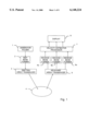
- FIG. 1 shows schematically a block diagram of the main components of the system.
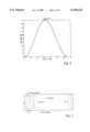
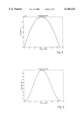
- FIG. 2 shows the amplitude scaling factors or equivalently the apodization used for the emit beam former.
- FIG. 3 shows a drawing of the linear array transducers used for emitting and also for receiving the field in the preferred embodiment.
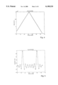
- FIG. 4 shows the time delay values for each element of the receiving transducer array used when making the left received signal.
- FIG. 5 shows the amplitude scaling factors for each element of the receiving transducer array used when making the left received signal.
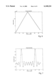
- FIG. 6 shows the time delay values for each element of the receiving transducer array used when making the right received signal.
- FIG. 7 shows the amplitude scaling factors for each element of the receiving transducer array used when making the right received signal.
- FIG. 8 shows the time delay values for each element of the receiving transducer array used when making the center received signal.
- FIG. 9 shows the amplitude scaling factors for each element of the receiving transducer array used when making the center received signal.
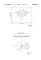
- FIG. 10 shows the lateral spatial oscillation of the pulsed field used in the preferred embodiment.
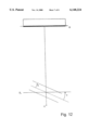
- FIG. 11 shows the definition of axial and lateral velocity for the computer experiment.
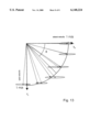
- FIG. 12 shows the simulation setup.
- FIG. 13 shows the resulting velocities when using this embodiment.
- FIG. 1 is shown an example of a preferred embodiment of an apparatus according to the invention.
- This embodiment of the invention has its application within diagnostic medical ultrasound for the measurement of blood flow velocity.
- a typical example is the determination of blood flow in peripheral vessels such as arteries in an arm, a leg, or in the carotid artery.
- Another example is estimation of blood flow of a major vessel in the thorax, where only a small window or aperture between the ribs is available.
- the blood flow is substantially parallel to the surface, i.e. the person's skin, and consequently transverse to the direction of the probing field, when the probe is placed directly on the skin.
- FIG. 1 the specific setup of the measuring apparatus itself is indicated schematically. It comprises a generator or pulser 1, an emit beam former 2, a linear array ultrasound emitting transducer 3, a linear array ultrasound receiving transducer 5, three receive beam formers 6a, 6b and 6c working in parallel and receiving signals from the receiving transducer 5, a microcomputer 7 for controlling the operation of the apparatus and calculating or estimating the velocities, and a color display 8.
- the pulser 1 generates a pulsed voltage signal with eight sinusoidal oscillations at a frequency of 3 MHz in each pulse, that is fed to the emit beam former 2.
- the emit beam former 2 splits up the signal from the pulser into a plurality of signals which are being fed to the respective elements of the emitting transducer array 3.
- the emit beam former 2 is capable of individually attenuating and delaying the signals to each of the elements of the transducer array 3. In this embodiment no delay is introduced during emission and in FIG. 2 the attenuation values are shown as a function of element number in the transducer.
- the same linear array transducer is used for both emitting and receiving the pulsed ultrasound field. It consists of 64 elements with an element width of 0.41 mm and a spacing between neighboring elements of 0.1 mm as shown in FIG. 3. The height of the elements is 5 mm.
- the emitted field from the transducer is scattered by the blood in the blood vessel 4 and part of the scattered field is received by the linear array transducer, and the signals from the individual elements are passed on to two of the receive beam formers, i.e. 6a and 6b.
- the signals from the elements are individually scaled in amplitude and individually delayed and are thereafter summed to yield a single output signal from each receive beam former.
- the first receive beam former 6a generates the left signal and the second receive beam former 6b generates the right signal.
- the delay values are shown as a function of transducer element number
- FIG. 5 the corresponding amplitude scaling factors are shown for the first receive beam former 6a.
- the delay values for the elements in the second receive beam former is shown in FIG. 6 and the corresponding amplitude scaling factors are shown in FIG. 7.
- the third receive beam former 6c generates the center signal with amplitude scaling factors shown in FIG. 8 and time delays in FIG. 9.
- Creating a field that oscillates spatially in the transverse direction of the propagation is consequently the basic element of the invention.
- the spatial oscillations are generated by the operation of the emit and/or the receive beam formers. They attenuate and delay the excitation signal to each individual transducer element in relationship to the others. This is called apodization.
- In transmit the delays are set to zero for all elements and the scaling factors are set to a Gaussian shape to reduce the sidelobes of the beam.
- the delays of the receive beam formers are operated so that two plane waves intersect each other at the place of investigation and the amplitude scaling is done with two sinc functions (sin(x-x 0 )/(x-x 0 ), where x is the lateral position on the aperture and x 0 is the position of the center of the peak in the sinc function, one centered at each half of the aperture.
- This generates a pulse-echo field that oscillates spatially in the transverse direction suitable for the velocity estimation. This is documented through the simulation of the field from which the lateral oscillation is shown in FIG. 10.
- One set of samples is taken for each pulsed field received, and the samples for one line is denoted x(i) and y(i).
- 50 pulsed fields have been emitted and received, so that 50 samples are available.
- the axial velocity is used for selecting the samples from the left and right signals from the two other beams formers.
- the samples taken from the left signals, denoted g t (t), are given by ##EQU2## so as to compensate for the influence from the axial movement of the blood.
- samples taken from the right signals, denoted g r (t) is given by ##EQU3##
- the functionality of the apparatus is examined for two-dimensional velocity vector measurement. It is the vector situated in the image plane.
- the two directions are called the axial and the lateral velocity as shown in FIG. 11.
- the axial velocity is parallel to the direction of propagation of the pulse.
- the lateral velocity is perpendicular to the direction of propagation and is situated in the image plane.
- the image plane coincides with the center line of the linear array.
- the functionality of the apparatus is experimentally documented by simulations.
- the simulation is performed using the impulse response method developed by Tupholme and by Stepanishen (Tupholme 1969; Stepanishen, 1970) in the implementation developed by Jensen and Svendsen (1992).
- the high accuracy of this approach, when compared to measurements, is described in Jensen (1991).
- the paper showed that the simulations were within 1% of the measured ultrasound fields.
- the simulation approach is applicable for pulsed fields and is used for three dimensional modeling the response of multiple scatterers.
- the simulated situation is shown in FIG. 12.
- a vessel of 10 mm diameter is placed 70 mm from the center the transducer array, i.e. on the axis of the transducer.
- the vessel contains plug flow (all blood scatterers have the same velocity) and the 15,000 scatterers in the vessel have a Gaussian amplitude distribution with zero mean value and unit variance. This ensures fully developed speckle in the response from the blood model.
- the simulation is done for constant velocity of 1 m/s and a varying angle ( ⁇ ) for the flow vector. The angles used are 0, 15, 35, 55, 75, and 90 degrees.
- the result of the simulation is shown in FIG. 13.
- the true velocity vectors are indicated by the individual arrows.
- the gray ellipses for each vector velocity estimate respectively indicate the standard deviation for both the axial estimation and the lateral estimation.
- the lateral standard deviation is the semi-major axis and the axial standard deviation is the semi-minor axis.
- the mean values are illustrated by the respective circles at the centers of the ellipses.
- the velocity estimation has only been done at a fixed distance from the transducer in the apparatus. Due to the use of a non-focused field it is easy to dynamically change the focusing of the three receive beam formers to generate the spatially oscillating field at other depths for the same pulse emitted.
- the apparatus described here only estimated the velocity in a plane, but it can easily be changed to give the full three dimensional velocity vector.
- a two-dimensional matrix transducer must then be used a described by Smith et al. (1990).
- the same emission field can be used since it is unfocused.
- An extra set of two receive beam formers must then be employed to make the velocity estimation in the y-direction perpendicular to both the z-and x-directions.
Landscapes
- Physics & Mathematics (AREA)
- Engineering & Computer Science (AREA)
- Radar, Positioning & Navigation (AREA)
- Remote Sensing (AREA)
- Acoustics & Sound (AREA)
- General Physics & Mathematics (AREA)
- Computer Networks & Wireless Communication (AREA)
- Multimedia (AREA)
- Aviation & Aerospace Engineering (AREA)
- Measurement Of Velocity Or Position Using Acoustic Or Ultrasonic Waves (AREA)
- Radar Systems Or Details Thereof (AREA)
- Ultra Sonic Daignosis Equipment (AREA)
Priority Applications (1)
| Application Number | Priority Date | Filing Date | Title |
|---|---|---|---|
| US09/222,773 US6148224A (en) | 1996-07-02 | 1998-12-30 | Apparatus and method for determining movements and velocities of moving objects |
Applications Claiming Priority (3)
| Application Number | Priority Date | Filing Date | Title |
|---|---|---|---|
| US2110196P | 1996-07-02 | 1996-07-02 | |
| PCT/DK1997/000287 WO1998000719A2 (fr) | 1996-07-02 | 1997-07-01 | Dispositif et procede pour determiner les deplacements et les vitesses d'objets en mouvement |
| US09/222,773 US6148224A (en) | 1996-07-02 | 1998-12-30 | Apparatus and method for determining movements and velocities of moving objects |
Related Parent Applications (1)
| Application Number | Title | Priority Date | Filing Date |
|---|---|---|---|
| PCT/DK1997/000287 Continuation WO1998000719A2 (fr) | 1996-07-02 | 1997-07-01 | Dispositif et procede pour determiner les deplacements et les vitesses d'objets en mouvement |
Publications (1)
| Publication Number | Publication Date |
|---|---|
| US6148224A true US6148224A (en) | 2000-11-14 |
Family
ID=21802345
Family Applications (1)
| Application Number | Title | Priority Date | Filing Date |
|---|---|---|---|
| US09/222,773 Expired - Lifetime US6148224A (en) | 1996-07-02 | 1998-12-30 | Apparatus and method for determining movements and velocities of moving objects |
Country Status (6)
| Country | Link |
|---|---|
| US (1) | US6148224A (fr) |
| EP (1) | EP0909395B1 (fr) |
| JP (1) | JP4100709B2 (fr) |
| AU (1) | AU3254897A (fr) |
| DE (1) | DE69710725T2 (fr) |
| WO (1) | WO1998000719A2 (fr) |
Cited By (44)
| Publication number | Priority date | Publication date | Assignee | Title |
|---|---|---|---|---|
| US6370264B1 (en) * | 1999-04-07 | 2002-04-09 | Steven C Leavitt | Method and apparatus for ultrasonic color flow imaging |
| US6725076B1 (en) * | 1999-05-10 | 2004-04-20 | B-K Medical A/S | Vector velocity estimation using directional beam forming and cross correlation |
| US6859659B1 (en) * | 1999-05-10 | 2005-02-22 | B-K Medical A/S | Estimation of vector velocity |
| US20050240123A1 (en) * | 2004-04-14 | 2005-10-27 | Mast T D | Ultrasound medical treatment system and method |
| US20050261610A1 (en) * | 2004-05-21 | 2005-11-24 | Mast T D | Transmit apodization of an ultrasound transducer array |
| US20070161904A1 (en) * | 2006-11-10 | 2007-07-12 | Penrith Corporation | Transducer array imaging system |
| US20080110266A1 (en) * | 2006-11-10 | 2008-05-15 | Penrith Corporation | Transducer array imaging system |
| US20080114245A1 (en) * | 2006-11-10 | 2008-05-15 | Randall Kevin S | Transducer array imaging system |
| US20080114251A1 (en) * | 2006-11-10 | 2008-05-15 | Penrith Corporation | Transducer array imaging system |
| US20080112265A1 (en) * | 2006-11-10 | 2008-05-15 | Penrith Corporation | Transducer array imaging system |
| US20080114249A1 (en) * | 2006-11-10 | 2008-05-15 | Penrith Corporation | Transducer array imaging system |
| US20080114239A1 (en) * | 2006-11-10 | 2008-05-15 | Penrith Corporation | Transducer array imaging system |
| US20080114255A1 (en) * | 2006-11-10 | 2008-05-15 | Penrith Corporation | Transducer array imaging system |
| US20080114241A1 (en) * | 2006-11-10 | 2008-05-15 | Penrith Corporation | Transducer array imaging system |
| US20080110261A1 (en) * | 2006-11-10 | 2008-05-15 | Penrith Corporation | Transducer array imaging system |
| US20080194964A1 (en) * | 2007-02-08 | 2008-08-14 | Randall Kevin S | Ultrasound imaging systems |
| US20080194963A1 (en) * | 2007-02-08 | 2008-08-14 | Randall Kevin S | Probes for ultrasound imaging systems |
| US20080194960A1 (en) * | 2007-02-08 | 2008-08-14 | Randall Kevin S | Probes for ultrasound imaging systems |
| US20080194962A1 (en) * | 2007-02-08 | 2008-08-14 | Randall Kevin S | Methods for verifying the integrity of probes for ultrasound imaging systems |
| US20080194961A1 (en) * | 2007-02-08 | 2008-08-14 | Randall Kevin S | Probes for ultrasound imaging systems |
| US7883468B2 (en) | 2004-05-18 | 2011-02-08 | Ethicon Endo-Surgery, Inc. | Medical system having an ultrasound source and an acoustic coupling medium |
| US7951095B2 (en) | 2004-05-20 | 2011-05-31 | Ethicon Endo-Surgery, Inc. | Ultrasound medical system |
| US8220334B2 (en) | 2006-11-10 | 2012-07-17 | Penrith Corporation | Transducer array imaging system |
| WO2013054149A1 (fr) * | 2011-10-11 | 2013-04-18 | B-K Medical Aps | Imagerie tridimensionnelle (3d) ultrasonore d'estimation de la vitesse vectorielle transversale d'oscillation |
| US8490489B2 (en) | 2006-11-10 | 2013-07-23 | Siemens Medical Solutions Usa, Inc. | Transducer array imaging system |
| US8499634B2 (en) | 2006-11-10 | 2013-08-06 | Siemens Medical Solutions Usa, Inc. | Transducer array imaging system |
| US8696573B2 (en) | 2008-11-10 | 2014-04-15 | Canon Kabushiki Kaisha | Ultrasonographic diagnostic system and ultrasonic diagnostic device |
| WO2014140657A1 (fr) * | 2013-03-13 | 2014-09-18 | B-K Medical Aps | Imagerie ultrasonore à flux vectoriel (vfi) avec tracé de courbe |
| US8911373B2 (en) | 2012-04-03 | 2014-12-16 | B-K Medical Aps | Vector flow ultrasound imaging |
| US9005144B2 (en) | 2001-05-29 | 2015-04-14 | Michael H. Slayton | Tissue-retaining systems for ultrasound medical treatment |
| US20150141832A1 (en) * | 2013-11-19 | 2015-05-21 | Versitech Limited | Apparatus for ultrasound flow vector imaging and methods thereof |
| US9132287B2 (en) | 2004-06-14 | 2015-09-15 | T. Douglas Mast | System and method for ultrasound treatment using grating lobes |
| US9170330B2 (en) | 2012-09-13 | 2015-10-27 | Analogic Corporation | Velocity estimation for vector flow imaging (VFI) in ultrasound |
| US20150331103A1 (en) * | 2012-11-28 | 2015-11-19 | B-K Medical Aps | Angle Independent Velocity Spectrum Determination |
| WO2015180069A1 (fr) * | 2014-05-28 | 2015-12-03 | 深圳迈瑞生物医疗电子股份有限公司 | Système et procédé d'imagerie échographique |
| US9261596B2 (en) | 2001-05-29 | 2016-02-16 | T. Douglas Mast | Method for monitoring of medical treatment using pulse-echo ultrasound |
| WO2016139515A1 (fr) | 2015-03-02 | 2016-09-09 | B-K Medical Aps | Estimation non-invasive de variations de pression intravasculaire par ultrasons (us) déterminant des vecteurs de vitesse |
| WO2016139506A1 (fr) | 2015-03-02 | 2016-09-09 | B-K Medical Aps | Estimation de vitesse de vecteur de flux en imagerie ultrasonore ayant une oscillation transversale directionnelle |
| US9474503B2 (en) | 2011-12-27 | 2016-10-25 | Samsung Medison Co., Ltd. | Ultrasound system and method for detecting vector information using transmission delays |
| US9726647B2 (en) | 2015-03-17 | 2017-08-08 | Hemosonics, Llc | Determining mechanical properties via ultrasound-induced resonance |
| WO2018087584A1 (fr) | 2016-11-11 | 2018-05-17 | B-K Medical Aps | Imagerie 3d et/ou estimation de flux comportant un réseau de transducteurs 2d adressé en rangée-colonne |
| US10302752B2 (en) | 2016-08-31 | 2019-05-28 | B-K Medical Aps | Vector velocity estimation using transverse oscillation (TO) and synthetic aperture sequential beamforming (SASB) |
| US10448926B2 (en) * | 2016-02-26 | 2019-10-22 | B-K Medical Aps | Transverse oscillation vector estimation in ultrasound imaging |
| US10962524B2 (en) | 2011-02-15 | 2021-03-30 | HomoSonics LLC | Characterization of blood hemostasis and oxygen transport parameters |
Families Citing this family (26)
| Publication number | Priority date | Publication date | Assignee | Title |
|---|---|---|---|---|
| GB9809943D0 (en) * | 1998-05-08 | 1998-07-08 | Amersham Pharm Biotech Ab | Microfluidic device |
| NL1010061C2 (nl) * | 1998-09-10 | 2000-03-13 | Universiteit Van Maastricht | Detectie van vectoriële snelheidsverdeling. |
| WO2007092054A2 (fr) | 2006-02-06 | 2007-08-16 | Specht Donald F | procEDE et appareil permettant de visualiser les artEres coronaires A l'aide d'ultrasons |
| EP2088932B1 (fr) | 2006-10-25 | 2020-04-08 | Maui Imaging, Inc. | Procédé et appareil de production d'images ultrasonores au moyen d'une pluralité d'orifices |
| US9282945B2 (en) | 2009-04-14 | 2016-03-15 | Maui Imaging, Inc. | Calibration of ultrasound probes |
| US9339256B2 (en) | 2007-10-01 | 2016-05-17 | Maui Imaging, Inc. | Determining material stiffness using multiple aperture ultrasound |
| US9247926B2 (en) | 2010-04-14 | 2016-02-02 | Maui Imaging, Inc. | Concave ultrasound transducers and 3D arrays |
| US9788813B2 (en) | 2010-10-13 | 2017-10-17 | Maui Imaging, Inc. | Multiple aperture probe internal apparatus and cable assemblies |
| KR101659910B1 (ko) | 2008-08-08 | 2016-09-27 | 마우이 이미징, 인코포레이티드 | 다중 구경 의료용 초음파를 통한 이미징 및 애드온 시스템의 동기화 |
| JP5485373B2 (ja) | 2009-04-14 | 2014-05-07 | マウイ イマギング,インコーポレーテッド | 複数開口の超音波アレイ位置合せ装置 |
| KR102322776B1 (ko) | 2010-02-18 | 2021-11-04 | 마우이 이미징, 인코포레이티드 | 초음파 이미지를 구성하는 방법 및 이를 위한 다중-개구 초음파 이미징 시스템 |
| JP6407719B2 (ja) | 2011-12-01 | 2018-10-17 | マウイ イマギング,インコーポレーテッド | ピングベース及び多数開口ドップラー超音波を用いた運動の検出 |
| JP2015503404A (ja) | 2011-12-29 | 2015-02-02 | マウイ イマギング,インコーポレーテッド | 任意経路のmモード超音波イメージング |
| KR20130102913A (ko) * | 2012-03-08 | 2013-09-23 | 삼성메디슨 주식회사 | 조직의 이동 속도 및 방향 획득 방법 및 장치 |
| EP2833791B1 (fr) | 2012-03-26 | 2022-12-21 | Maui Imaging, Inc. | Procédés pour l'amélioration de la qualité d'images ultrasonores par l'application de facteurs de pondération |
| CN104620128B (zh) | 2012-08-10 | 2017-06-23 | 毛伊图像公司 | 多孔径超声探头的校准 |
| CN103676827A (zh) | 2012-09-06 | 2014-03-26 | Ip音乐集团有限公司 | 用于远程控制音频设备的系统和方法 |
| US9986969B2 (en) | 2012-09-06 | 2018-06-05 | Maui Imaging, Inc. | Ultrasound imaging system memory architecture |
| WO2014160291A1 (fr) | 2013-03-13 | 2014-10-02 | Maui Imaging, Inc. | Alignement de groupements de transducteurs à ultrasons et ensemble de sonde à ouvertures multiples |
| US9883848B2 (en) | 2013-09-13 | 2018-02-06 | Maui Imaging, Inc. | Ultrasound imaging using apparent point-source transmit transducer |
| US10401493B2 (en) | 2014-08-18 | 2019-09-03 | Maui Imaging, Inc. | Network-based ultrasound imaging system |
| US9855022B2 (en) | 2015-01-19 | 2018-01-02 | B-K Medical Aps | 3-D flow estimation using row-column addressed transducer arrays |
| CN107613878B (zh) | 2015-03-30 | 2021-04-06 | 毛伊图像公司 | 用于检测物体运动的超声成像系统和方法 |
| EP4697068A3 (fr) | 2016-01-27 | 2026-04-22 | Maui Imaging, Inc. | Imagerie ultrasonore à sondes à matrice creuse |
| JP7724853B2 (ja) | 2020-10-21 | 2025-08-18 | マウイ イマギング,インコーポレーテッド | 多数開口超音波を用いた組織の特徴付けのためのシステム及び方法 |
| EP4236811A4 (fr) | 2020-11-02 | 2024-10-09 | Maui Imaging, Inc. | Systèmes et procédés d'amélioration de la qualité d'image ultrasonore |
Citations (12)
| Publication number | Priority date | Publication date | Assignee | Title |
|---|---|---|---|---|
| US4265126A (en) * | 1979-06-15 | 1981-05-05 | General Electric Company | Measurement of true blood velocity by an ultrasound system |
| US4327739A (en) * | 1979-03-22 | 1982-05-04 | Horst Chmiel | Noninvasive measurement of blood flow rate utilizing ultrasound |
| US4693319A (en) * | 1984-10-08 | 1987-09-15 | Fujitsu Limited | Correlation detection type ultrasound blood flowmeter |
| EP0270733A1 (fr) * | 1986-11-11 | 1988-06-15 | Applied Biometrics, Inc. | Appareil de mesure de l'écoulement du sang artériel |
| US4896674A (en) * | 1985-04-30 | 1990-01-30 | Kabushiki Kaisha Toshiba | Ultrasonic diagnosing system |
| US4979513A (en) * | 1987-10-14 | 1990-12-25 | Matsushita Electric Industrial Co., Ltd. | Ultrasonic diagnostic apparatus |
| EP0430093A2 (fr) * | 1989-11-27 | 1991-06-05 | Acoustic Imaging Technologies Corporation | Système d'imagerie doppler employant des ultrasons avec annuleur de signaux et contre-réaction analogique |
| US5320105A (en) * | 1991-12-11 | 1994-06-14 | U.S. Philips Corporation | Ultrasonic echograph for measuring high velocities of blood flows |
| US5349960A (en) * | 1991-10-01 | 1994-09-27 | Olympus Optical Co., Ltd. | Ultrasonic diagnosis apparatus |
| EP0638285A1 (fr) * | 1993-08-09 | 1995-02-15 | Hewlett-Packard Company | Système d'ultra-son dans le domaine de fréquences et méthode pour mesurer l'écoulement du fluide |
| US5390676A (en) * | 1990-08-31 | 1995-02-21 | Hitachi, Ltd. | Ultrasonic flowmeter |
| US5810731A (en) * | 1995-11-13 | 1998-09-22 | Artann Laboratories | Method and apparatus for elasticity imaging using remotely induced shear wave |
-
1997
- 1997-07-01 EP EP97928135A patent/EP0909395B1/fr not_active Expired - Lifetime
- 1997-07-01 JP JP50376798A patent/JP4100709B2/ja not_active Expired - Fee Related
- 1997-07-01 WO PCT/DK1997/000287 patent/WO1998000719A2/fr not_active Ceased
- 1997-07-01 AU AU32548/97A patent/AU3254897A/en not_active Abandoned
- 1997-07-01 DE DE69710725T patent/DE69710725T2/de not_active Expired - Lifetime
-
1998
- 1998-12-30 US US09/222,773 patent/US6148224A/en not_active Expired - Lifetime
Patent Citations (12)
| Publication number | Priority date | Publication date | Assignee | Title |
|---|---|---|---|---|
| US4327739A (en) * | 1979-03-22 | 1982-05-04 | Horst Chmiel | Noninvasive measurement of blood flow rate utilizing ultrasound |
| US4265126A (en) * | 1979-06-15 | 1981-05-05 | General Electric Company | Measurement of true blood velocity by an ultrasound system |
| US4693319A (en) * | 1984-10-08 | 1987-09-15 | Fujitsu Limited | Correlation detection type ultrasound blood flowmeter |
| US4896674A (en) * | 1985-04-30 | 1990-01-30 | Kabushiki Kaisha Toshiba | Ultrasonic diagnosing system |
| EP0270733A1 (fr) * | 1986-11-11 | 1988-06-15 | Applied Biometrics, Inc. | Appareil de mesure de l'écoulement du sang artériel |
| US4979513A (en) * | 1987-10-14 | 1990-12-25 | Matsushita Electric Industrial Co., Ltd. | Ultrasonic diagnostic apparatus |
| EP0430093A2 (fr) * | 1989-11-27 | 1991-06-05 | Acoustic Imaging Technologies Corporation | Système d'imagerie doppler employant des ultrasons avec annuleur de signaux et contre-réaction analogique |
| US5390676A (en) * | 1990-08-31 | 1995-02-21 | Hitachi, Ltd. | Ultrasonic flowmeter |
| US5349960A (en) * | 1991-10-01 | 1994-09-27 | Olympus Optical Co., Ltd. | Ultrasonic diagnosis apparatus |
| US5320105A (en) * | 1991-12-11 | 1994-06-14 | U.S. Philips Corporation | Ultrasonic echograph for measuring high velocities of blood flows |
| EP0638285A1 (fr) * | 1993-08-09 | 1995-02-15 | Hewlett-Packard Company | Système d'ultra-son dans le domaine de fréquences et méthode pour mesurer l'écoulement du fluide |
| US5810731A (en) * | 1995-11-13 | 1998-09-22 | Artann Laboratories | Method and apparatus for elasticity imaging using remotely induced shear wave |
Non-Patent Citations (2)
| Title |
|---|
| German Brockhaus Enzyklop a die, vol. 18, pp. 22 23, (1992). * |
| German Brockhaus Enzyklopadie, vol. 18, pp. 22-23, (1992). |
Cited By (77)
| Publication number | Priority date | Publication date | Assignee | Title |
|---|---|---|---|---|
| US6370264B1 (en) * | 1999-04-07 | 2002-04-09 | Steven C Leavitt | Method and apparatus for ultrasonic color flow imaging |
| US6725076B1 (en) * | 1999-05-10 | 2004-04-20 | B-K Medical A/S | Vector velocity estimation using directional beam forming and cross correlation |
| US6859659B1 (en) * | 1999-05-10 | 2005-02-22 | B-K Medical A/S | Estimation of vector velocity |
| US9261596B2 (en) | 2001-05-29 | 2016-02-16 | T. Douglas Mast | Method for monitoring of medical treatment using pulse-echo ultrasound |
| US9005144B2 (en) | 2001-05-29 | 2015-04-14 | Michael H. Slayton | Tissue-retaining systems for ultrasound medical treatment |
| US20050240123A1 (en) * | 2004-04-14 | 2005-10-27 | Mast T D | Ultrasound medical treatment system and method |
| US7883468B2 (en) | 2004-05-18 | 2011-02-08 | Ethicon Endo-Surgery, Inc. | Medical system having an ultrasound source and an acoustic coupling medium |
| US7951095B2 (en) | 2004-05-20 | 2011-05-31 | Ethicon Endo-Surgery, Inc. | Ultrasound medical system |
| US20050261610A1 (en) * | 2004-05-21 | 2005-11-24 | Mast T D | Transmit apodization of an ultrasound transducer array |
| US7695436B2 (en) * | 2004-05-21 | 2010-04-13 | Ethicon Endo-Surgery, Inc. | Transmit apodization of an ultrasound transducer array |
| US9132287B2 (en) | 2004-06-14 | 2015-09-15 | T. Douglas Mast | System and method for ultrasound treatment using grating lobes |
| US20080114239A1 (en) * | 2006-11-10 | 2008-05-15 | Penrith Corporation | Transducer array imaging system |
| US20080114245A1 (en) * | 2006-11-10 | 2008-05-15 | Randall Kevin S | Transducer array imaging system |
| US20080114255A1 (en) * | 2006-11-10 | 2008-05-15 | Penrith Corporation | Transducer array imaging system |
| US20080114241A1 (en) * | 2006-11-10 | 2008-05-15 | Penrith Corporation | Transducer array imaging system |
| US20080110261A1 (en) * | 2006-11-10 | 2008-05-15 | Penrith Corporation | Transducer array imaging system |
| US9295444B2 (en) | 2006-11-10 | 2016-03-29 | Siemens Medical Solutions Usa, Inc. | Transducer array imaging system |
| US20070161904A1 (en) * | 2006-11-10 | 2007-07-12 | Penrith Corporation | Transducer array imaging system |
| US9084574B2 (en) | 2006-11-10 | 2015-07-21 | Siemens Medical Solution Usa, Inc. | Transducer array imaging system |
| US20080110266A1 (en) * | 2006-11-10 | 2008-05-15 | Penrith Corporation | Transducer array imaging system |
| US20080114252A1 (en) * | 2006-11-10 | 2008-05-15 | Penrith Corporation | Transducer array imaging system |
| US20080114249A1 (en) * | 2006-11-10 | 2008-05-15 | Penrith Corporation | Transducer array imaging system |
| US20080112265A1 (en) * | 2006-11-10 | 2008-05-15 | Penrith Corporation | Transducer array imaging system |
| US8656783B2 (en) | 2006-11-10 | 2014-02-25 | Siemens Medical Solutions Usa, Inc. | Transducer array imaging system |
| US20080114251A1 (en) * | 2006-11-10 | 2008-05-15 | Penrith Corporation | Transducer array imaging system |
| US7984651B2 (en) | 2006-11-10 | 2011-07-26 | Penrith Corporation | Transducer array imaging system |
| US8079263B2 (en) | 2006-11-10 | 2011-12-20 | Penrith Corporation | Transducer array imaging system |
| US8166822B1 (en) | 2006-11-10 | 2012-05-01 | Penrith Corporation | Transducer array imaging system |
| US8220334B2 (en) | 2006-11-10 | 2012-07-17 | Penrith Corporation | Transducer array imaging system |
| US8312771B2 (en) | 2006-11-10 | 2012-11-20 | Siemens Medical Solutions Usa, Inc. | Transducer array imaging system |
| US8600299B2 (en) | 2006-11-10 | 2013-12-03 | Siemens Medical Solutions Usa, Inc. | Transducer array imaging system |
| US8490489B2 (en) | 2006-11-10 | 2013-07-23 | Siemens Medical Solutions Usa, Inc. | Transducer array imaging system |
| US8499634B2 (en) | 2006-11-10 | 2013-08-06 | Siemens Medical Solutions Usa, Inc. | Transducer array imaging system |
| US8499635B2 (en) | 2006-11-10 | 2013-08-06 | Siemens Medical Solutions Usa, Inc. | Transducer array imaging system |
| US20080194963A1 (en) * | 2007-02-08 | 2008-08-14 | Randall Kevin S | Probes for ultrasound imaging systems |
| US7891230B2 (en) | 2007-02-08 | 2011-02-22 | Penrith Corporation | Methods for verifying the integrity of probes for ultrasound imaging systems |
| US20080194964A1 (en) * | 2007-02-08 | 2008-08-14 | Randall Kevin S | Ultrasound imaging systems |
| US20080194962A1 (en) * | 2007-02-08 | 2008-08-14 | Randall Kevin S | Methods for verifying the integrity of probes for ultrasound imaging systems |
| US20080194961A1 (en) * | 2007-02-08 | 2008-08-14 | Randall Kevin S | Probes for ultrasound imaging systems |
| US20080194960A1 (en) * | 2007-02-08 | 2008-08-14 | Randall Kevin S | Probes for ultrasound imaging systems |
| US9706976B2 (en) | 2007-02-08 | 2017-07-18 | Siemens Medical Solutions Usa, Inc. | Ultrasound imaging systems and methods of performing ultrasound procedures |
| US8696573B2 (en) | 2008-11-10 | 2014-04-15 | Canon Kabushiki Kaisha | Ultrasonographic diagnostic system and ultrasonic diagnostic device |
| US11680940B2 (en) | 2011-02-15 | 2023-06-20 | Hemosonics Llc | Characterization of blood hemostasis and oxygen transport parameters |
| US10962524B2 (en) | 2011-02-15 | 2021-03-30 | HomoSonics LLC | Characterization of blood hemostasis and oxygen transport parameters |
| WO2013054149A1 (fr) * | 2011-10-11 | 2013-04-18 | B-K Medical Aps | Imagerie tridimensionnelle (3d) ultrasonore d'estimation de la vitesse vectorielle transversale d'oscillation |
| US9636086B2 (en) * | 2011-10-11 | 2017-05-02 | B-K Medical Aps | Three dimensional (3D) transverse oscillation vector velocity ultrasound imaging |
| US20140257103A1 (en) * | 2011-10-11 | 2014-09-11 | B-K Medical Aps | Three Dimensional (3D) Transverse Oscillation Vector Velocity Ultrasound Imaging |
| US9474503B2 (en) | 2011-12-27 | 2016-10-25 | Samsung Medison Co., Ltd. | Ultrasound system and method for detecting vector information using transmission delays |
| US8911373B2 (en) | 2012-04-03 | 2014-12-16 | B-K Medical Aps | Vector flow ultrasound imaging |
| US9170330B2 (en) | 2012-09-13 | 2015-10-27 | Analogic Corporation | Velocity estimation for vector flow imaging (VFI) in ultrasound |
| US10359515B2 (en) * | 2012-11-28 | 2019-07-23 | B-K Medical Aps | Angle independent velocity spectrum determination |
| US20150331103A1 (en) * | 2012-11-28 | 2015-11-19 | B-K Medical Aps | Angle Independent Velocity Spectrum Determination |
| US9702972B2 (en) * | 2012-11-28 | 2017-07-11 | B-K Medical Aps | Angle independent velocity spectrum determination |
| US20160015366A1 (en) * | 2013-03-13 | 2016-01-21 | B-K Medical Aps | Ultrasound vector flow imaging (vfi) with curve tracing |
| WO2014140657A1 (fr) * | 2013-03-13 | 2014-09-18 | B-K Medical Aps | Imagerie ultrasonore à flux vectoriel (vfi) avec tracé de courbe |
| US10716543B2 (en) * | 2013-03-13 | 2020-07-21 | B-K Medical Aps | Ultrasound vector flow imaging (VFI) with curve tracing |
| CN105120761B (zh) * | 2013-03-13 | 2020-02-07 | B-K医疗公司 | 具有曲线描迹的超声矢量流成像(vfi) |
| CN105120761A (zh) * | 2013-03-13 | 2015-12-02 | B-K医疗公司 | 具有曲线描迹的超声矢量流成像(vfi) |
| US10335113B2 (en) | 2013-11-19 | 2019-07-02 | Versitech Limited | Apparatus for ultrasound flow vector imaging and methods thereof |
| US10231695B2 (en) * | 2013-11-19 | 2019-03-19 | Versitech Limited | Apparatus for ultrasound flow vector imaging and methods thereof |
| CN106456118A (zh) * | 2013-11-19 | 2017-02-22 | 港大科桥有限公司 | 超声流体向量成像装置及其方法 |
| US11154272B2 (en) | 2013-11-19 | 2021-10-26 | Versitech Limited | Apparatus for ultrasound flow vector imaging and methods thereof |
| US20150141832A1 (en) * | 2013-11-19 | 2015-05-21 | Versitech Limited | Apparatus for ultrasound flow vector imaging and methods thereof |
| CN105530870B (zh) * | 2014-05-28 | 2019-02-22 | 深圳迈瑞生物医疗电子股份有限公司 | 一种超声成像方法和系统 |
| WO2015180069A1 (fr) * | 2014-05-28 | 2015-12-03 | 深圳迈瑞生物医疗电子股份有限公司 | Système et procédé d'imagerie échographique |
| US11259784B2 (en) | 2014-05-28 | 2022-03-01 | Shenzhen Mindray Bio-Medical Electronics Co., Ltd. | Ultrasound imaging method and system |
| US10945700B2 (en) | 2015-03-02 | 2021-03-16 | B-K Medical Aps | Non-invasive estimation of intravascular pressure changes using vector velocity ultrasound (US) |
| WO2016139506A1 (fr) | 2015-03-02 | 2016-09-09 | B-K Medical Aps | Estimation de vitesse de vecteur de flux en imagerie ultrasonore ayant une oscillation transversale directionnelle |
| WO2016139515A1 (fr) | 2015-03-02 | 2016-09-09 | B-K Medical Aps | Estimation non-invasive de variations de pression intravasculaire par ultrasons (us) déterminant des vecteurs de vitesse |
| US9726647B2 (en) | 2015-03-17 | 2017-08-08 | Hemosonics, Llc | Determining mechanical properties via ultrasound-induced resonance |
| US10495613B2 (en) | 2015-03-17 | 2019-12-03 | Hemosonics, Llc | Determining mechanical properties via ultrasound-induced resonance |
| US11002712B2 (en) | 2015-03-17 | 2021-05-11 | Hemosonics Llc | Determining mechanical properties via ultrasound-induced resonance |
| US11656206B2 (en) | 2015-03-17 | 2023-05-23 | Hemosonics Llc | Determining mechanical properties via ultrasound-induced resonance |
| US12163925B2 (en) | 2015-03-17 | 2024-12-10 | Hemosonics Llc | Determining mechanical properties via ultrasound-induced resonance |
| US10448926B2 (en) * | 2016-02-26 | 2019-10-22 | B-K Medical Aps | Transverse oscillation vector estimation in ultrasound imaging |
| US10302752B2 (en) | 2016-08-31 | 2019-05-28 | B-K Medical Aps | Vector velocity estimation using transverse oscillation (TO) and synthetic aperture sequential beamforming (SASB) |
| WO2018087584A1 (fr) | 2016-11-11 | 2018-05-17 | B-K Medical Aps | Imagerie 3d et/ou estimation de flux comportant un réseau de transducteurs 2d adressé en rangée-colonne |
Also Published As
| Publication number | Publication date |
|---|---|
| JP4100709B2 (ja) | 2008-06-11 |
| AU3254897A (en) | 1998-01-21 |
| EP0909395A2 (fr) | 1999-04-21 |
| DE69710725D1 (de) | 2002-04-04 |
| WO1998000719A2 (fr) | 1998-01-08 |
| WO1998000719A3 (fr) | 1998-03-12 |
| JP2001503853A (ja) | 2001-03-21 |
| DE69710725T2 (de) | 2002-11-21 |
| EP0909395B1 (fr) | 2002-02-27 |
Similar Documents
| Publication | Publication Date | Title |
|---|---|---|
| US6148224A (en) | Apparatus and method for determining movements and velocities of moving objects | |
| Jensen et al. | A new method for estimation of velocity vectors | |
| Tanter et al. | Ultrafast compound imaging for 2-D motion vector estimation: Application to transient elastography | |
| EP1175613B1 (fr) | Estimation de la vitesse vectorielle | |
| EP1175621B1 (fr) | Estimation de velocite par la mise en forme et la correlation croisee de faisceaux diriges | |
| Udesen et al. | Investigation of transverse oscillation method | |
| Jensen | A new estimator for vector velocity estimation [medical ultrasonics] | |
| EP0008517B1 (fr) | Système de représentation double de signaux ultrasoniques émis répétitivement par un convertisseur unique de modalité Doppler | |
| US7753847B2 (en) | Ultrasound vibrometry | |
| US7542790B2 (en) | Apparatus and method for velocity estimation in synthetic aperture imaging | |
| Jensen et al. | Directional synthetic aperture flow imaging | |
| EP1194920B1 (fr) | Imagerie ultrasonique recursive | |
| JP2849159B2 (ja) | 超音波診断装置 | |
| JP2001187054A (ja) | 超音波ビーム経路の数値的最適化方式 | |
| EP2766738B1 (fr) | Imagerie tridimensionnelle (3d) ultrasonore d'estimation de la vitesse vectorielle transversale d'oscillation | |
| Newhouse et al. | Three-dimensional vector flow estimation using two transducers and spectral width | |
| Tortoli et al. | Accurate Doppler angle estimation for vector flow measurements | |
| JPH0759774A (ja) | 流体流検知方法 | |
| US5373848A (en) | Ultrasonic time-domain method for sensing fluid flow | |
| JPH03155843A (ja) | 超音波診断装置 | |
| US20250271399A1 (en) | A method for determining the velocity of a natural shear wave propagating in a medium | |
| Katakura et al. | Ultrasonic vector velocity measurement by projection computed velocimetry | |
| Lupotti et al. | Decorrelation-based blood flow velocity estimation: effect of spread of flow velocity, linear flow velocity gradients, and parabolic flow | |
| Dunmire et al. | Brief history of vector Doppler | |
| Jensen et al. | An improved estimation and focusing scheme for vector velocity estimation |
Legal Events
| Date | Code | Title | Description |
|---|---|---|---|
| AS | Assignment |
Owner name: B-K MEDICAL A/S, DENMARK Free format text: ASSIGNMENT OF ASSIGNORS INTEREST;ASSIGNOR:JENSEN, JORGEN ARENDT;REEL/FRAME:009859/0874 Effective date: 19990305 |
|
| STCF | Information on status: patent grant |
Free format text: PATENTED CASE |
|
| FEPP | Fee payment procedure |
Free format text: PAYOR NUMBER ASSIGNED (ORIGINAL EVENT CODE: ASPN); ENTITY STATUS OF PATENT OWNER: LARGE ENTITY |
|
| FPAY | Fee payment |
Year of fee payment: 4 |
|
| REMI | Maintenance fee reminder mailed | ||
| FPAY | Fee payment |
Year of fee payment: 8 |
|
| SULP | Surcharge for late payment |
Year of fee payment: 7 |
|
| FEPP | Fee payment procedure |
Free format text: PAYER NUMBER DE-ASSIGNED (ORIGINAL EVENT CODE: RMPN); ENTITY STATUS OF PATENT OWNER: LARGE ENTITY Free format text: PAYOR NUMBER ASSIGNED (ORIGINAL EVENT CODE: ASPN); ENTITY STATUS OF PATENT OWNER: LARGE ENTITY |
|
| FPAY | Fee payment |
Year of fee payment: 12 |