US6148888A - Method and system for measuring and adjusting pressure of tires - Google Patents
Method and system for measuring and adjusting pressure of tires Download PDFInfo
- Publication number
- US6148888A US6148888A US08/836,661 US83666197A US6148888A US 6148888 A US6148888 A US 6148888A US 83666197 A US83666197 A US 83666197A US 6148888 A US6148888 A US 6148888A
- Authority
- US
- United States
- Prior art keywords
- pressure
- tire
- temperature
- air supplying
- valve
- Prior art date
- Legal status (The legal status is an assumption and is not a legal conclusion. Google has not performed a legal analysis and makes no representation as to the accuracy of the status listed.)
- Expired - Fee Related
Links
Images


Classifications
-
- B—PERFORMING OPERATIONS; TRANSPORTING
- B60—VEHICLES IN GENERAL
- B60S—SERVICING, CLEANING, REPAIRING, SUPPORTING, LIFTING, OR MANOEUVRING OF VEHICLES, NOT OTHERWISE PROVIDED FOR
- B60S5/00—Servicing, maintaining, repairing, or refitting of vehicles
- B60S5/04—Supplying air for tyre inflation
- B60S5/043—Supplying air for tyre inflation characterised by the inflation control means or the drive of the air pressure system
- B60S5/046—Supplying air for tyre inflation characterised by the inflation control means or the drive of the air pressure system using electrical or electronical means
-
- B—PERFORMING OPERATIONS; TRANSPORTING
- B60—VEHICLES IN GENERAL
- B60C—VEHICLE TYRES; TYRE INFLATION; TYRE CHANGING; CONNECTING VALVES TO INFLATABLE ELASTIC BODIES IN GENERAL; DEVICES OR ARRANGEMENTS RELATED TO TYRES
- B60C23/00—Devices for measuring, signalling, controlling, or distributing tyre pressure or temperature, specially adapted for mounting on vehicles; Arrangement of tyre inflating devices on vehicles, e.g. of pumps or of tanks; Tyre cooling arrangements
- B60C23/02—Signalling devices actuated by tyre pressure
- B60C23/04—Signalling devices actuated by tyre pressure mounted on the wheel or tyre
- B60C23/0408—Signalling devices actuated by tyre pressure mounted on the wheel or tyre transmitting the signals by non-mechanical means from the wheel or tyre to a vehicle body mounted receiver
- B60C23/0422—Signalling devices actuated by tyre pressure mounted on the wheel or tyre transmitting the signals by non-mechanical means from the wheel or tyre to a vehicle body mounted receiver characterised by the type of signal transmission means
- B60C23/0433—Radio signals
Definitions
- the present invention relates, as its title indicates, to a method which allows to measure tire pressure and adjust it to reference values, taking into account the variations which may have been produced in said reference values due to changes in tire temperature.
- the problem for the user when checking the pressure is that he has to obtain the pressure values corresponding to front and rear wheels; however these values vary depending upon whether the tires are cold or warm. As the quantification of these factors is subjective, the user usually chooses an average pressure or a reference pressure value that he considers the most suitable.
- the system which is object of this invention has been developed, which allows to determine the pressure equivalent to the nominal pressure given by the tire manufacturer, as a function of the temperature of the tire at the moment of carrying out the reading and to supply said equivalent pressure by means of a pressured-air machine, which forms part of the system.
- the equivalent pressure is therefore a pressure which under temperature conditions different from the environmental temperature would be the appropriate one for the use of the tire.
- the method of the invention therefore permits, during the pressure checking and during the adjustment of the same, to know which is the present pressure of the tire, the temperature inside the same and the corresponding pressure that it should have, as a function of the temperature inside the tire as well as the nominal pressure at environmental temperature given by the manufacturer.
- the user can effect the pressure adjustment either manually, or by using an automatic adjustment procedure.
- the system of the invention uses a sensor mechanism installed inside the tire.
- the system consists of a valve which may be the conventional inflating valve which incorporates a thermocouple, a portable pressure tester and a pressured-air supplying machine.
- the valve incorporates a thermocouple which emerges out from the back zone of the valve, thereby permitting the thermocouple remain located inside the tire when the valve is mounted thereon, the conductors of the thermocouple having at the ends thereof a pair of contact points outside the valve at the front zone of the same.
- the portable pressure tester of digital type, has a mouthpiece for connection with the valve, and contact points which may be connected to the contact points of the valve thermocouple, the tester being capable of reading the pressure of the tire and the temperature inside the same simultaneously.
- the tester has several push-buttons by means of which the nominal pressure value of the tire at ambient temperature, which is a value given by the manufacturer, is is introduced therein; and a display on which nominal pressure values, temperature detected by the thermocouple, present pressure of the tire and the correct pressure of the tire are visualized.
- the later is calculated from the data corresponding to the nominal pressure at environmental temperature and the detected temperature, by means of a microprocessor included in the tester.
- Tire volume variation is negligible in spite of pressure changes, as the pressure variation affects the rigidity of the tire and the inside canvas frame avoids a substantial change of volume.
- P 0 is the nominal pressure recommended by the manufacturer at environmental temperature (293 K, equal to 20° C.).
- P 1 is the corrected equivalent pressure in terms of temperature
- T is temperature (in °C.) measured inside the tire by the thermocouple
- P 0 is the pressure at ambient temperature (293 K) recommended by the vehicle manufacturer.
- the system of this invention further comprises an air supplying machine to adjust tire pressure, taking into consideration the temperature inside the same.
- This machine has a connection mouth for connection with the tire valve, provided with contact means suitable for making contact with the contact points of the thermocouple when the connection mouth is connected to the valve, the machine thus performing simultaneous reading of values corresponding to the present pressure of tire and the present temperature inside the same.
- the air supplying machine has a keyboard, by means of which the nominal pressure value is introduced; a microprocessor adapted to calculate an equivalent pressure, using data from the nominal pressure and the temperature inside the tire; and a display on which data regarding nominal pressure, present pressure, temperature and equivalent pressure are visualized.
- connection mouth for connection with the valve further has means to effect a safe blocking on the valve when said connection mouth is fixed on the same.
- the arrangement of the blocking means is such as to permit the mouth to remain firmly attached to the valve during the operation of pressure adjustment, whereas when the operation is ended, it can be easily unblocked by the user by pulling from an external case of the same.
- This disposition is made possible due to the use of a generally cylindrical body with longitudinal grooves which allow said body to be subject to perimeteral compression, thus reducing its diameter, thereby making possible a firm grip of the same over a valve.
- said air supplying machine optionally incorporates an auxiliary tool which permits to screw or to unscrew the core of the valve if deemed necessary.
- Said tool consists of an essentially cylindrical body which has a cavity at one end, axially disposed to allow the placing of a rod shaped element therein whose free end has a configuration suitable for being coupled to a core.
- Said tool further has, at the opposite end thereof, another cavity axially arranged, which has a wrench-like configuration which permits the manipulation of valves, end caps or any element related to this field.
- the tire pressure adjustment is carried out by a pneumatic equipment included within the machine, said equipment being activated either by a control circuit governed by the microprocessor if the user chooses the equivalent pressure calculated by the machine; or manually by means of using push-buttons (+) and (-), in case that the user prefers to put a pressure different to the calculated one.
- the process of checking the present temperature and pressure of the tire is carried out by means of a sensor and emitter device attached to the surface of the rim of the tire which remains inside the tire, so that in operation conditions, it can directly detect said present pressure and temperature of the tire.
- Thw data obtaines are subsequently converted into electronic signals which are then converted into radiofrequency waves and are transmitted towards the outside of the tire.
- Said radiofrequency waves are later received by a portable receiver set arranged as a remote control apparatus which also serves for switching said receiver and emitter device on.
- Said remote control apparatus further has several push-buttons by means of which the nominal pressure value of the tire at ambient temperature, which is a value given by the manufacturer, is manually introduced therein; and a display means for displaying values of the nominal pressure, the present temperature and pressure both detected by the sensor device, as well as the equivalent pressure of the tire which is calculated by a microprocessor included in the remote control apparatus in the same manner as described hereinbefore in the case of the pressure portable tester.
- the user introduces this data into an air supplying machine with characteristics as mentioned above, in order to adjust the tire pressure.
- the air supplying mouth would not need the use of contact means to perform the proper reading of the present temperature and pressure inside the tire.
- the receiver and emitter device essentially consists of at least one thermocouple, a pressure detector, a circuit for reception and emission radiofrequency waves, a circuit for converting radiofrequency waves into electronic signals and vice versa and a power supply circuit which operates by using electronic energy supplying batteries.
- the air supplying machine incorporates means for receiving radiofrequency signals emitted from said remote control apparatus in order to detect said signals and process them to obtain data related to the equivalent pressure which has to be supplied to the tire by the air supplying machine itself.
- said machine may incorporate a radiofrequency waves receiver and a converter for converting radiofrequency waves into electronic signals which are later supplied to the microprocessor incorporated in the air supplying machine.
- the user will initially use the remote control apparatus to detect the present temperature and pressure of the tire, calculate the equivalent pressure to be given to the tire, and transmit the value thereof to the air supplying machine, which after receiving said value, starts the operation of adjusting the tire pressure in accordance with the equivalent pressure.
- the remote control apparatus may be incorporated in the front panel inside the vehicle where the user can control and check the pressure and the temperature of the tire without having to get out of the vehicle, or even perform the controlling and checking during the driving.
- the remote control apparatus will effect the measurement of present pressure and temperature of each tire of vehicle separately and it will visualize them successively, or by according to the selection choice of the user.
- the microprocessor of the remote control apparatus must be programmed to effect independant readings of each one of the wheels.
- the method and system for vehicle tire pressure measuring and adjusting described above further allows the automatic execution of certain functions, without a direct intervention of the user.
- One of said functions is to perform the pressure measurement and adjustment of each tire of the vehicle using a valve locating mechanism and a subsequent connection of the air supplying mouth-pieces to each valve.
- the wheels of the vehicle are located on rollers operated by means of a motor or a similar mechanism so that their synchronized rotation makes the vehicle wheel rotate untill its valve is placed at a pre-determined position where it will receive an air supplying mouth-piece which carries out the measurement and the further adjustment of tire pressure.
- FIG. 1 shows a front view of the valve which forms a part of the system for measurement and adjustment of tire pressure, mounted on a tire, wherein the peripheral material of the same has been longitudinally cross-sectioned to allow the observation of the thermocouple.
- FIG. 2 shows a front view of the pressure tester, wherein the connection mouth of the same has been partially cross-sectioned.
- FIG. 3 represents a partially cross-sectioned front view of the connection mouth of the pressured-air supplying machine.
- FIG. 4 shows a front view of the air supplying machine.
- FIG. 5 shows a block diagram of the air supplying machine.
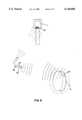
- FIG. 6 shows a diagram of the setting of a sensor and emitter device on a wheel rim as well as the remote control apparatus in relation to the tire and the air supplying machine.
- FIG. 7 is a block diagram of the main components of a sensor and emitter device.
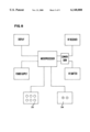
- FIG. 8 is a block diagram of a remote control apparatus.
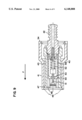
- FIG. 9 is a front view of an air supplying mouth with blocking means axially cross-sectioned according to a vertical plane.
- FIG. 9(a) is a perspective view of a blocking body of the mouth of FIG. 9.
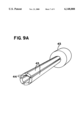
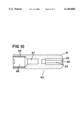
- FIG. 10 is a front view of an auxiliary tool employed to screw and to unscrew the valve core of a valve, axially cross-sectioned according to a vertical plane.
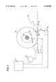
- FIG. 11 is a diagram of an automatic pressure measurement and adjustment system using rotatable rollers.
- the tire pressure measuring and adjusting system consists of a valve (1), a pressure tester (2) and an air supplying machine (3).
- the valve (1) incorporates a thermocouple (4) which juts out the rear zone of the same such that the thermocouple (4) remains located inside the tire (5); one of the conductors (6) of the thermocouple is connected to a cylindrical-shape metal body (7) of the valve (1) whereas the other conductor (8) is connected to a peripheral ring (9) embeded inside the insulating material which evolves the metallic body (7), thereby, both contact means (7) and (9) remain separated and electronically isolated.
- the pressure tester (2) has a tip (10), which can be coupled to the valve (1) to read the inner pressure of the tire (5); this tip has an extension made of insulating material (11) and a central conductive part (12).
- the present pressure and temperature values are registered by a microprocessor inside the tester (2).
- the tester has several push-buttons (14) externally which have pre-determined values assigned thereto, corresponding to the pressure values most commonly used. By switching on the corresponding push-button (14) the nominal pressure value, at environmental temperature, given by the vehicle manufacturer, is introduced in the microprocessor.
- the tester (2) further has two other push-buttons (15) which allow to increase or reduce the nominal pressure value as provided by means of any of the push-buttons (14), these being employed to introduce the nominal pressure value in the microprocessor in the case where said value would not coincide with anyone of those assigned to the push-buttons (14).
- the microprocessor of the tester (2) When the microprocessor of the tester (2) already has the nominal pressure values of the tire, the temperature inside the same and its present pressure, it calculates the pressure equivalent to the nominal one bearing in mind the temperature variation and it visualizes all data on the display (16) of the tester, so that user can check if the present pressure corresponds to the calculated equivalent pressure.
- the machine (3) in charge of adjusting tire pressure incorporates a host (17) which ends at a mouthpiece (18), suitable to be coupled onto the valve (1).
- the mouthpiece (18) defines an external isolating part (19), from which a contact means (20) emerges, and an inner part (21) made of conductive material which forms another contact means; such that when the mouthpiece (18) of the machine (3) is coupled onto the valve (1), contact means (20) and (21) of the mouthpiece (18) are connected to those (7) and (9) of the thermocouple, the machine (3) simultaneously performing the registration of the temperature and pressure in a microprocessor located inside the same.
- the mouthpiece (40) consists of a evolving body (41) which has a cylindric portion with a larger diameter over the surface of which there are several ribs presented to facilitate the handling of the mouthpiece and another cylindrical portion with a smaller diameter which forms together with the first portion the evolving body inside which the mouthpiece components are located.
- Said components include an outlet tip (42) which is threaded at an end inside a blocking body (43).
- This blocking body (43) has a generally cylindrical configuration which, in one end where said outlet tip (42) is threaded, has a longer diameter and along the remaining surface has several longitudinal grooves (44) as can be seen in FIG. 9(a). Said grooves allow the mobility of movable portions (45) adjacent to the same as the blocking body (43) is made of a preferably metallic material with certain flexibility in a radial direction.
- the blocking body (43) has mobility in an axial direction inside the evolving body (41) whereas movable portions (45) remain located in the same.
- Said evolving body (41) has at its end opposite to the outlet tip (42) and on its inner surface, a perimetric recess (46). Additionally, the blocking body (43) has in the free ends of each one of the mobile portions (45) a salient portion (47).
- the blocking body (43) has mobility inside the evolving body (41) untill the point of coincidence of salients (47) with the perimetric recess (46). At this point salients (47) fit into perimetric recess (46) due to the effect of mobile portions (45) which tend to open outwards in a radial direction thereby obtaining a larger diameter in the opening part (48). Therefore, when the end of a tire valve is introduced into the opening (48) of the blocking body (43) when the latter is in a situation of the opening (48) having its larger diameter, the evolving body (41) slides over the blocking body (43) in a direction opposite to the entry of the valve, for example in the direction of arrow "F" in FIG. 9. Said movement makes the salient portions (47) of the blocking body (43) to move out of the perimeteral recess (46) thereby reducing the diameter of the opening (48) which has the end of the tire valve inside.
- Said diameter reduction of opening (48) on the valve produces the blocking effect of the blocking body (43) on the valve.
- the evolving body (41) slides in a direction opposite to arrow "F” untill salient portions (47) again fit into the perimeteral recess (46), thereby increasing the diameter of opening (48) which allows the valve of the same to be moved out.
- the mouthpiece (40) further consists of a series of pieces which allow its functionality such as a cylindrical sleeve (49) which at a first end thereof is attached to the outlet tip (42) and at another end has a base surface (50) with a central orifice through which rod (51) passes.
- a cylindrical sleeve (49) which at a first end thereof is attached to the outlet tip (42) and at another end has a base surface (50) with a central orifice through which rod (51) passes.
- This latter at the end corresponding to the entry of the tire valve, has a plane base which rests over the valve core, and at the opposite end it has a cubic or rectangular-prismatic configuration which permits the passage of air and which rsts on an end of a spring (52) whose effect is that rod (51) exerts pressure on valve core.
- an elastic joint (53), made of rubber for example, is arranged whose objective is to provide sealing when the valve is introduced into the opening (48) and lays on the joint (53). Additionally the cervoclip (54) arranged in the opening corresponding to outlet tip (42) tends to avoid the inside mechanism of the evolving body (41) from moving out.
- the air supplying machine (3) optionally has an additional tool which permits the threading and unthreading the core of tire valves.
- Said tool (60), as shown in FIG. 10 consists of an essentially cylindrical body (61) which has at an end a cavity (62) axially disposed to permit the lodging of a rod shaped utensil (63), whose free end (64) has a suitable configuration to couple on a core. Said rod (63) remains fixed inside the cylindrical body (61).
- tool (60) has another cavity (65) axially disposed which has a first portion (66) with a larger diameter and a keyshaped configuration which permits operation on valves, end caps or any element related to the field of tires.
- Said cavity (65) also consists of a second portion (67) intended to allow the introduction of the ends of valves while they are being manipulated by means of the first keyshaped portion (66).
- the machine (3) in the same manner as that of the tester, externally has push-buttons (22) which have specific values assigned thereto corresponding to the pressure values mostly used. Each one of said push-buttons (22) may preferably have a colour specially assigned to its pressure value.
- the corresponding push-button (22) By activating the corresponding push-button (22), the nominal pressure value of tire at environmental temperature as given by the vehicle manufacturer, is introduced into the microprocessor, the microprocessor making the calculation of the pressure equivalent to the nominal depending on temperature.
- the machine (3) further incorporates two push-buttons (23) which permit to adjust the nominal pressure value in the case where it would not coincide with any push-button (22).
- the microprocessor of the machine is connected to a display (24), on which data regarding nominal pressure, present pressure, equivalent pressure and temperature are displayed; and to a control circuit (25) which controls a pneumatic equipment (26) in charge of adjusting the tire pressure by introducing or extracting air in and out of the same respectively, by means of the hose (17).
- the microprocessor calculates the equivalent pressure and acts on the pneumatic equipment (26) by means of control circuit (25), adjusting the tire pressure to the calculated equivalent pressure value.
- the machine then providing the selected pressure, as if it were a conventional machine.
- FIGS. 6, 7 and 8 an alternative embodiment of the object of the invention is described, according to which a sensor and emitter device (30) is attached to the surface of a tire rim (31) so that when said rim carries the corresponding pneumatic tire (shown in broken lines), said device (30) remains inside the tire to effect the detection of the present pressure and temperature of tire.
- Said device as it can be seen in FIG. 7, consists of a microprocessor which governs the operation of the same, a radiofrequency wave receiver and emitter, a converter of radiofrequency waves into electronic signals and vice versa, a pressure meter and a thermocouple.
- the remote control apparatus (32) consists of a microprocessor, a display device (DISPLAY), a radiofrequency wave receiver and emitter, a converter of radiofrequency waves into electronic signals and vice versa, a supply device, normally a battery, a keyboard (33) and several push-buttons (34) to increase and decrease values shown in the display.
- the user uses the keyboard (33) to send the correspondig signal for commanding the sensor and emitter device (30) so that the latter performs the corresponding readings of pressure and temperature.
- said command is carried out through radiofrequency waves which are transmitted through the transmitter set of the remote control apparatus and which are received by the receiver of the sensor and emitter device (30).
- Said radiofrequency waves are later converted into electronic signals by means of the converter of said device (30), which are sent to the microprocessor of the same.
- the latter having received the corresponding signal, effects the measurement of the pressure by the pressure meter, and of the temperature by the thermocouple of the sensor and emitter device (30).
- the microprocessor sends the signals corresponding to measured data to the converter for their convertion into radiofrequency waves which are emitted towards the outside by the radiofrequency emitter of the sensor and emitter device (30).
- the waves emitted by said device (30) are received by the radiofrequency receiver of the remote control apparatus (32) and once converted into electronic signals by the converter of said apparatus, they are sent to the microprocessor of the same. This latter, according to the received values calculates the equivalent pressure with which the tire is to be provided. All data related to the present pressure and temperature and nominal pressure can be visualized through the display of the remote control apparatus (32).
- the air supplying machine (3) incorporates a radiofrequency waves receiver device (35) capable of receiving the waves emitted by the remote control apparatus (32) as it is shown in FIG. 6.
- a radiofrequency waves receiver device (35) capable of receiving the waves emitted by the remote control apparatus (32) as it is shown in FIG. 6.
- the user directs the remote control apparatus towards the air supplying machine (3) and by pressing the corresponding push-button, the user immediately sends by way of radiofrequency waves the value of the equivalent pressure to the receiver device (35) of the air supplying machine (3).
- Said receiver device (35) provides the microprocessor of the air supplying machine (3) with the value of the equivalent pressure by means of electronic signals, the microprocessor thus automatically starting to supply the equivalent pressure to the tire.
- the process for the reception of radiofrequency waves untill their sending to the microprocessor is similar to that of the sensor and emitter device (30) and that of the remote control apparatus (32) for which in order to avoid repetitions its detailed description is ommited.
- the air supplying machine may carry out, by means of its microprocessor, the calculation of the pressure equivalent to the nominal, so that in this case this task would not be carried out in the remote control apparatus; the latter therefore would only be limited to the sending of the values of the present temperature and pressure of tire to the air supplying machine.
- the remote control apparatus (32) may be installed into the vehicle, for example in the front panel of the inner space of the same, in such a manner that the user, for example the driver, while driving can effect the checking of the present pressure and temperature of each tire of the vehicle.
- the method for measurement and calculation of the equivalent pressure is similar to that of the previous case except that in this case the remote control apparatus would emit and receive radiofrequency waves related to each wheel through independent activator devices installed nearby each tire and intended to activating a sensor and emitter device (30) of each corresponding wheel.
- Said independent activator devices are installed in the bodywork of the vehicle and are connected by cables to the remote control apparatus installed inside the vehicle.
- the remote control apparatus displays the values corresponding to each wheel independently, either successively or by pushing a key corresponding to a wheel and further keys corresponding to other wheels.
- the method and the system for pressure measurement and adjustment described hereinabove further permit the execution of certain functions in an automatic manner and without the direct intervention of the user.
- One of said functions is to effect the pressure measurement and adjustment of all the tires of the vehicle automatically.
- said localization mechanism (70) consists of several rollers (71) arranged to allow the wheel (72) to be situated thereon, while they are capable of rotating around a respective axis (73) by means of the activation of a motor (79) or a similar system, in such a way that their synchronized rotation forces the wheel (72) to rotate around its axis (74).
- valve (75) Due to said rotation of the wheel (72), the tire valve (75) moves in a circular path untill a proximity detection device (76) detects its presence. The detection of the presence of valve (75) is communicated by electronic signals to a control equipment (77).
- Said equipment uses a microprocessor (not shown in figure) which governs the automatic operation of the whole system.
- valve (75) remains situated in a pre-determined position to later receive the air supplying mouthpiece (80).
- the microprocessor of the control equipment (77) commands a mechanism (78) for activating the air supplying mouthpiece (80) to make the latter move and be placed on the valve (75).
- This automatic operation system may be installed in places where vehicles call in order to obtain services such as a car wash, a vehicle technical inspection station, etc.
Landscapes
- Engineering & Computer Science (AREA)
- Mechanical Engineering (AREA)
- Measuring Fluid Pressure (AREA)
- Vehicle Cleaning, Maintenance, Repair, Refitting, And Outriggers (AREA)
Applications Claiming Priority (1)
| Application Number | Priority Date | Filing Date | Title |
|---|---|---|---|
| PCT/ES1995/000103 WO1997009187A1 (es) | 1995-09-01 | 1995-09-01 | Metodo y sistema de medicion y ajuste de presion de los neumaticos |
Publications (1)
| Publication Number | Publication Date |
|---|---|
| US6148888A true US6148888A (en) | 2000-11-21 |
Family
ID=8289214
Family Applications (1)
| Application Number | Title | Priority Date | Filing Date |
|---|---|---|---|
| US08/836,661 Expired - Fee Related US6148888A (en) | 1995-09-01 | 1995-09-01 | Method and system for measuring and adjusting pressure of tires |
Country Status (12)
| Country | Link |
|---|---|
| US (1) | US6148888A (de) |
| JP (1) | JPH10509934A (de) |
| AT (1) | ATE235385T1 (de) |
| AU (1) | AU711149B2 (de) |
| DE (1) | DE69530102T2 (de) |
| DK (1) | DK0791488T3 (de) |
| NZ (1) | NZ292925A (de) |
| PE (1) | PE20796A1 (de) |
| PT (1) | PT791488E (de) |
| TN (1) | TNSN96111A1 (de) |
| TR (1) | TR199501545A2 (de) |
| ZA (1) | ZA958149B (de) |
Cited By (19)
| Publication number | Priority date | Publication date | Assignee | Title |
|---|---|---|---|---|
| US6218937B1 (en) * | 1999-05-20 | 2001-04-17 | Sagem S.A. | System for monitoring the pressure of tires |
| US20030058118A1 (en) * | 2001-05-15 | 2003-03-27 | Wilson Kitchener C. | Vehicle and vehicle tire monitoring system, apparatus and method |
| US6630885B2 (en) | 2000-07-26 | 2003-10-07 | Bridgestone/Firestone North American Tire, Llc | Electronic tire management system |
| US20040127937A1 (en) * | 1998-07-25 | 2004-07-01 | Newton Michael David | Identification and communication system for inflatable devices |
| US20040153281A1 (en) * | 2003-02-05 | 2004-08-05 | Jaynes Harry M. | Temperature corrected tire pressure gauge and method |
| US20050033351A1 (en) * | 1998-07-25 | 2005-02-10 | Newton Michael David | Identification and communication system for inflatable devices |
| FR2862928A1 (fr) * | 2003-12-01 | 2005-06-03 | Emic | Systeme automatise et securise de gonflage pour vehicules equipes de pneumatiques |
| US20060002800A1 (en) * | 2004-06-30 | 2006-01-05 | Klein Christopher D | Compressor control apparatus |
| US20060055522A1 (en) * | 2004-09-13 | 2006-03-16 | Rimkus Robert A | Tire pressure characterization method and key fob |
| US7161476B2 (en) | 2000-07-26 | 2007-01-09 | Bridgestone Firestone North American Tire, Llc | Electronic tire management system |
| US20080133081A1 (en) * | 2006-11-30 | 2008-06-05 | Hunter Engineering Company | Integrated Tire Pressure Diagnostic System and Method |
| US7789112B1 (en) * | 2006-11-09 | 2010-09-07 | Wise Robert W | Method and system for inflating an inflatable object |
| US20120086098A1 (en) * | 2010-10-07 | 2012-04-12 | Texas Instruments Incorporated | Ionic isolation ring |
| US8266465B2 (en) | 2000-07-26 | 2012-09-11 | Bridgestone Americas Tire Operation, LLC | System for conserving battery life in a battery operated device |
| US8330579B2 (en) | 2007-07-05 | 2012-12-11 | Baxter International Inc. | Radio-frequency auto-identification system for dialysis systems |
| EP3056362A1 (de) * | 2015-02-12 | 2016-08-17 | MAN Truck & Bus AG | Verfahren und vorrichtung zur unterstützung eines fahrers eines fahrzeugs, insbesondere eines nutzfahrzeugs |
| CN107323436A (zh) * | 2017-05-25 | 2017-11-07 | 浙江绿源电动车有限公司 | 充气系统及其控制方法 |
| DE10164333B4 (de) | 2001-01-02 | 2019-05-09 | Trw Inc. | Einem Fahrzeug zugeordnetes ferngesteuertes Bequemlichkeits- und Informations- übertragungssystem |
| US20210091578A1 (en) * | 2014-09-09 | 2021-03-25 | Halo2Cloud, LLC | Portable power charger with air compressor |
Families Citing this family (4)
| Publication number | Priority date | Publication date | Assignee | Title |
|---|---|---|---|---|
| DE19851563A1 (de) * | 1998-11-09 | 2000-05-18 | Bosch Gmbh Robert | Automatisches Fahrzeug-Reifendruckmeß/-einstellsystem und Fahrzeug-Reifendruckmeß/-einstellverfahren |
| DE102005037600A1 (de) * | 2005-08-05 | 2007-02-08 | Drescher, Rüdiger | Ventilklappe |
| TWI460086B (zh) | 2010-12-17 | 2014-11-11 | Orange Electronic Co Ltd | Standard pressure setting method for wireless tire pressure sensor |
| DE102018212838A1 (de) * | 2018-08-01 | 2020-02-06 | Ford Global Technologies, Llc | System und ein Verfahren zum Überwachen eines Reifendrucks |
Citations (8)
| Publication number | Priority date | Publication date | Assignee | Title |
|---|---|---|---|---|
| US3913632A (en) * | 1974-03-04 | 1975-10-21 | Walter H Dudar | Vehicle tire inflating system |
| US4334215A (en) * | 1979-04-27 | 1982-06-08 | Tire-Tronics, Inc. | Continuous heat and pressure surveillance system for pneumatic tires |
| FR2548780A1 (fr) * | 1983-07-04 | 1985-01-11 | Pingeot Bardin Ets | Manometre de controle de la pression d'un pneumatique et dispositif de gonflage equipe d'un tel manometre |
| EP0284895A1 (de) * | 1987-03-17 | 1988-10-05 | Bayerische Motoren Werke Aktiengesellschaft, Patentabteilung AJ-3 | Verfahren zum fülldruckrichtigen Befüllen eines Luftreifens eines Fahrzeuges mit einer Luftreifenfülldrucküberwachungseinrichtung |
| EP0301443A1 (de) * | 1987-07-23 | 1989-02-01 | Bridgestone Corporation | Reifenprüfeinrichtung |
| US5179981A (en) * | 1988-05-25 | 1993-01-19 | Eaton Corporation | Fault detection method for central tire inflation system |
| WO1994003349A1 (es) * | 1992-08-04 | 1994-02-17 | Loureiro Benimeli Fermin Jaime | Systema para hinchar neumaticos |
| WO1994004398A1 (de) * | 1992-08-12 | 1994-03-03 | Georg Ackermann | Einrichtung zum befüllen eines fahrzeugreifens |
-
1995
- 1995-09-01 NZ NZ292925A patent/NZ292925A/xx unknown
- 1995-09-01 US US08/836,661 patent/US6148888A/en not_active Expired - Fee Related
- 1995-09-01 AT AT95932024T patent/ATE235385T1/de not_active IP Right Cessation
- 1995-09-01 AU AU35235/95A patent/AU711149B2/en not_active Ceased
- 1995-09-01 DE DE69530102T patent/DE69530102T2/de not_active Expired - Fee Related
- 1995-09-01 JP JP9510879A patent/JPH10509934A/ja active Pending
- 1995-09-01 DK DK95932024T patent/DK0791488T3/da active
- 1995-09-01 PT PT95932024T patent/PT791488E/pt unknown
- 1995-09-14 PE PE1995278988A patent/PE20796A1/es not_active Application Discontinuation
- 1995-09-27 ZA ZA958149A patent/ZA958149B/xx unknown
- 1995-12-07 TR TR95/01545A patent/TR199501545A2/xx unknown
-
1996
- 1996-08-30 TN TNTNSN96111A patent/TNSN96111A1/fr unknown
Patent Citations (8)
| Publication number | Priority date | Publication date | Assignee | Title |
|---|---|---|---|---|
| US3913632A (en) * | 1974-03-04 | 1975-10-21 | Walter H Dudar | Vehicle tire inflating system |
| US4334215A (en) * | 1979-04-27 | 1982-06-08 | Tire-Tronics, Inc. | Continuous heat and pressure surveillance system for pneumatic tires |
| FR2548780A1 (fr) * | 1983-07-04 | 1985-01-11 | Pingeot Bardin Ets | Manometre de controle de la pression d'un pneumatique et dispositif de gonflage equipe d'un tel manometre |
| EP0284895A1 (de) * | 1987-03-17 | 1988-10-05 | Bayerische Motoren Werke Aktiengesellschaft, Patentabteilung AJ-3 | Verfahren zum fülldruckrichtigen Befüllen eines Luftreifens eines Fahrzeuges mit einer Luftreifenfülldrucküberwachungseinrichtung |
| EP0301443A1 (de) * | 1987-07-23 | 1989-02-01 | Bridgestone Corporation | Reifenprüfeinrichtung |
| US5179981A (en) * | 1988-05-25 | 1993-01-19 | Eaton Corporation | Fault detection method for central tire inflation system |
| WO1994003349A1 (es) * | 1992-08-04 | 1994-02-17 | Loureiro Benimeli Fermin Jaime | Systema para hinchar neumaticos |
| WO1994004398A1 (de) * | 1992-08-12 | 1994-03-03 | Georg Ackermann | Einrichtung zum befüllen eines fahrzeugreifens |
Cited By (32)
| Publication number | Priority date | Publication date | Assignee | Title |
|---|---|---|---|---|
| US20040127937A1 (en) * | 1998-07-25 | 2004-07-01 | Newton Michael David | Identification and communication system for inflatable devices |
| US20050033351A1 (en) * | 1998-07-25 | 2005-02-10 | Newton Michael David | Identification and communication system for inflatable devices |
| US6884255B1 (en) * | 1998-07-25 | 2005-04-26 | Huntleigh Technology, Plc | Identification and communication system for inflatable devices |
| US7398803B2 (en) | 1998-07-25 | 2008-07-15 | Huntleigh Technology Ltd | Identification and communication system for inflatable devices |
| US6218937B1 (en) * | 1999-05-20 | 2001-04-17 | Sagem S.A. | System for monitoring the pressure of tires |
| US7161476B2 (en) | 2000-07-26 | 2007-01-09 | Bridgestone Firestone North American Tire, Llc | Electronic tire management system |
| US6630885B2 (en) | 2000-07-26 | 2003-10-07 | Bridgestone/Firestone North American Tire, Llc | Electronic tire management system |
| US8151127B2 (en) | 2000-07-26 | 2012-04-03 | Bridgestone Americas Tire Operations, Llc | System for conserving battery life in a battery operated device |
| US8266465B2 (en) | 2000-07-26 | 2012-09-11 | Bridgestone Americas Tire Operation, LLC | System for conserving battery life in a battery operated device |
| DE10164333B4 (de) | 2001-01-02 | 2019-05-09 | Trw Inc. | Einem Fahrzeug zugeordnetes ferngesteuertes Bequemlichkeits- und Informations- übertragungssystem |
| US20030058118A1 (en) * | 2001-05-15 | 2003-03-27 | Wilson Kitchener C. | Vehicle and vehicle tire monitoring system, apparatus and method |
| US6983209B2 (en) * | 2003-02-05 | 2006-01-03 | Jaynes Harry M | Temperature corrected tire pressure gauge and method |
| US20040153281A1 (en) * | 2003-02-05 | 2004-08-05 | Jaynes Harry M. | Temperature corrected tire pressure gauge and method |
| FR2862928A1 (fr) * | 2003-12-01 | 2005-06-03 | Emic | Systeme automatise et securise de gonflage pour vehicules equipes de pneumatiques |
| US20060002800A1 (en) * | 2004-06-30 | 2006-01-05 | Klein Christopher D | Compressor control apparatus |
| US7556478B2 (en) | 2004-06-30 | 2009-07-07 | Campbell Hausfeld/Scott Fetzer Company | Compressor control apparatus |
| US7215243B2 (en) * | 2004-09-13 | 2007-05-08 | General Motors Corporation | Tire pressure characterization method and key fob |
| US20060055522A1 (en) * | 2004-09-13 | 2006-03-16 | Rimkus Robert A | Tire pressure characterization method and key fob |
| US7789112B1 (en) * | 2006-11-09 | 2010-09-07 | Wise Robert W | Method and system for inflating an inflatable object |
| US20080133081A1 (en) * | 2006-11-30 | 2008-06-05 | Hunter Engineering Company | Integrated Tire Pressure Diagnostic System and Method |
| US8392048B2 (en) * | 2006-11-30 | 2013-03-05 | Hunter Engineering Company | Integrated tire pressure diagnostic system and method |
| US8330579B2 (en) | 2007-07-05 | 2012-12-11 | Baxter International Inc. | Radio-frequency auto-identification system for dialysis systems |
| US8546903B2 (en) * | 2010-10-07 | 2013-10-01 | Texas Instruments Incorporated | Ionic isolation ring |
| US20120086098A1 (en) * | 2010-10-07 | 2012-04-12 | Texas Instruments Incorporated | Ionic isolation ring |
| US11824383B2 (en) * | 2014-09-09 | 2023-11-21 | Bollinger Industries, Inc. | Portable power charger with air compressor |
| US20210091578A1 (en) * | 2014-09-09 | 2021-03-25 | Halo2Cloud, LLC | Portable power charger with air compressor |
| US9963003B2 (en) | 2015-02-12 | 2018-05-08 | Man Truck & Bus Ag | Method and device for assisting a driver of a vehicle, in particular a commercial vehicle |
| RU2705886C2 (ru) * | 2015-02-12 | 2019-11-12 | Ман Трак Унд Бас Аг | Способ и устройство для оказания поддержки водителю транспортного средства, в частности автомобиля промышленного назначения |
| EP4119365A1 (de) * | 2015-02-12 | 2023-01-18 | MAN Truck & Bus SE | Luftventil für fahrzeugreifen |
| EP3056362A1 (de) * | 2015-02-12 | 2016-08-17 | MAN Truck & Bus AG | Verfahren und vorrichtung zur unterstützung eines fahrers eines fahrzeugs, insbesondere eines nutzfahrzeugs |
| CN107323436B (zh) * | 2017-05-25 | 2020-04-10 | 浙江绿源电动车有限公司 | 充气系统及其控制方法 |
| CN107323436A (zh) * | 2017-05-25 | 2017-11-07 | 浙江绿源电动车有限公司 | 充气系统及其控制方法 |
Also Published As
| Publication number | Publication date |
|---|---|
| PT791488E (pt) | 2003-08-29 |
| ATE235385T1 (de) | 2003-04-15 |
| TR199501545A2 (tr) | 1997-03-21 |
| DK0791488T3 (da) | 2003-07-21 |
| AU3523595A (en) | 1997-03-27 |
| TNSN96111A1 (fr) | 1998-12-31 |
| NZ292925A (en) | 1999-01-28 |
| JPH10509934A (ja) | 1998-09-29 |
| DE69530102D1 (de) | 2003-04-30 |
| AU711149B2 (en) | 1999-10-07 |
| PE20796A1 (es) | 1996-05-30 |
| ZA958149B (en) | 1997-03-27 |
| DE69530102T2 (de) | 2004-01-29 |
Similar Documents
| Publication | Publication Date | Title |
|---|---|---|
| US6148888A (en) | Method and system for measuring and adjusting pressure of tires | |
| EP1323552B1 (de) | Reifenzustandsüberwachungsgerät | |
| EP1215056B1 (de) | Vorrichtung und Verfahren zur Reifenzustandüberwachung | |
| US6414592B1 (en) | Tire condition sensor communication with tire location provided via manually inputted update | |
| EP0263251B1 (de) | Reifendruckfüller und Luftzufuhr, um einen gewünschten Reifendruck zu gewährleisten | |
| US6750761B1 (en) | Method for monitoring tire parameters | |
| US6826951B1 (en) | Tire management system and method for surveying and servicing a vehicle tire | |
| US6774778B2 (en) | Tire pressure monitoring device and code learning method therefor | |
| EP0791488A1 (de) | Verfahren und system zur messung und einstellung von reifendruck | |
| US8674821B2 (en) | Tire pressure monitoring apparatus | |
| US6737965B2 (en) | Tire condition monitoring apparatus | |
| EP1336512B1 (de) | Apparat zur Überwachung von Reifenbedingungen | |
| CA2263396A1 (en) | Off-the-road tire temperature and pressure monitoring system | |
| JP2009053089A (ja) | 車輪位置検出用の送受信機、車輪位置検出装置およびそれを備えたタイヤ空気圧検出装置 | |
| US7039508B2 (en) | Tire monitoring system with a wireless setting capability | |
| JP3945578B2 (ja) | タイヤ状態監視装置 | |
| CA2204138A1 (en) | Method and system for measuring and adjusting pressure of tyres | |
| US6954141B2 (en) | Apparatus and method for tire monitoring system | |
| WO1999036850A1 (en) | Tire management system and method for surveying and servicing a vehicle tire | |
| JP2000153703A (ja) | タイヤ空気圧警報装置及び送信信号を任意に操作できる制御治具 | |
| CN112406419A (zh) | 一种胎压控制设备及胎压控制方法 | |
| RU97108784A (ru) | Способ и система для измерения и регулировки давления в шине | |
| KR20070080888A (ko) | 타이어 압력 모니터링 시스템의 저주파수 시동기 일체형타이어 압력 모니티링 시스템 수신기 및 타이어 위치 학습방법 | |
| KR0167500B1 (ko) | 포터블 전자식 타이어 플랫 감지기 | |
| JPH01128200A (ja) | 水道用バルブにおける無線・有線両用式トルク計測装置 |
Legal Events
| Date | Code | Title | Description |
|---|---|---|---|
| AS | Assignment |
Owner name: FAST AIR, S.L., SPAIN Free format text: ASSIGNMENT OF ASSIGNORS INTEREST;ASSIGNOR:BENIMELI, FERMIN JAIME LOUREIRO;REEL/FRAME:008593/0889 Effective date: 19970521 |
|
| REMI | Maintenance fee reminder mailed | ||
| LAPS | Lapse for failure to pay maintenance fees | ||
| STCH | Information on status: patent discontinuation |
Free format text: PATENT EXPIRED DUE TO NONPAYMENT OF MAINTENANCE FEES UNDER 37 CFR 1.362 |
|
| FP | Lapsed due to failure to pay maintenance fee |
Effective date: 20041121 |