US6149126A - Valve for the metered introduction of evaporated fuel - Google Patents
Valve for the metered introduction of evaporated fuel Download PDFInfo
- Publication number
- US6149126A US6149126A US09/230,360 US23036099A US6149126A US 6149126 A US6149126 A US 6149126A US 23036099 A US23036099 A US 23036099A US 6149126 A US6149126 A US 6149126A
- Authority
- US
- United States
- Prior art keywords
- valve
- section
- nozzle
- valve seat
- cross
- Prior art date
- Legal status (The legal status is an assumption and is not a legal conclusion. Google has not performed a legal analysis and makes no representation as to the accuracy of the status listed.)
- Expired - Fee Related
Links
- 239000000446 fuel Substances 0.000 title claims abstract description 14
- 239000002828 fuel tank Substances 0.000 claims abstract description 10
- 238000002485 combustion reaction Methods 0.000 claims abstract description 5
- 238000007789 sealing Methods 0.000 claims description 5
- 238000001179 sorption measurement Methods 0.000 claims description 3
- 230000007704 transition Effects 0.000 claims 2
- 238000009423 ventilation Methods 0.000 abstract description 3
- 230000033228 biological regulation Effects 0.000 abstract description 2
- OKTJSMMVPCPJKN-UHFFFAOYSA-N Carbon Chemical compound [C] OKTJSMMVPCPJKN-UHFFFAOYSA-N 0.000 description 2
- 230000006978 adaptation Effects 0.000 description 2
- 230000008020 evaporation Effects 0.000 description 2
- 238000001704 evaporation Methods 0.000 description 2
- 230000005284 excitation Effects 0.000 description 2
- 230000014759 maintenance of location Effects 0.000 description 2
- 230000000295 complement effect Effects 0.000 description 1
- 239000006185 dispersion Substances 0.000 description 1
- 230000000694 effects Effects 0.000 description 1
- 239000013013 elastic material Substances 0.000 description 1
- 229920001971 elastomer Polymers 0.000 description 1
- 239000000806 elastomer Substances 0.000 description 1
- 239000000696 magnetic material Substances 0.000 description 1
- 230000001172 regenerating effect Effects 0.000 description 1
- 239000013589 supplement Substances 0.000 description 1
- 230000001960 triggered effect Effects 0.000 description 1
- 238000003466 welding Methods 0.000 description 1
Images

Classifications
-
- F—MECHANICAL ENGINEERING; LIGHTING; HEATING; WEAPONS; BLASTING
- F02—COMBUSTION ENGINES; HOT-GAS OR COMBUSTION-PRODUCT ENGINE PLANTS
- F02M—SUPPLYING COMBUSTION ENGINES IN GENERAL WITH COMBUSTIBLE MIXTURES OR CONSTITUENTS THEREOF
- F02M25/00—Engine-pertinent apparatus for adding non-fuel substances or small quantities of secondary fuel to combustion-air, main fuel or fuel-air mixture
- F02M25/08—Engine-pertinent apparatus for adding non-fuel substances or small quantities of secondary fuel to combustion-air, main fuel or fuel-air mixture adding fuel vapours drawn from engine fuel reservoir
-
- F—MECHANICAL ENGINEERING; LIGHTING; HEATING; WEAPONS; BLASTING
- F02—COMBUSTION ENGINES; HOT-GAS OR COMBUSTION-PRODUCT ENGINE PLANTS
- F02M—SUPPLYING COMBUSTION ENGINES IN GENERAL WITH COMBUSTIBLE MIXTURES OR CONSTITUENTS THEREOF
- F02M25/00—Engine-pertinent apparatus for adding non-fuel substances or small quantities of secondary fuel to combustion-air, main fuel or fuel-air mixture
- F02M25/08—Engine-pertinent apparatus for adding non-fuel substances or small quantities of secondary fuel to combustion-air, main fuel or fuel-air mixture adding fuel vapours drawn from engine fuel reservoir
- F02M25/0836—Arrangement of valves controlling the admission of fuel vapour to an engine, e.g. valve being disposed between fuel tank or absorption canister and intake manifold
Definitions
- the invention is based on a valve for the metered introduction of fuel evaporated from a fuel tank of an internal combustion engine into an intake tube of the engine.
- a valve of this kind has already been disclosed (DE-PS 42 29 110), which has a valve seat that is formed on an edge of an inlet cross section of a Laval nozzle, which a cylindrical valve member, which can be actuated by an electromagnet, rests against in the closed position.
- the valve seat consequently also represents an axial boundary of the Laval nozzle.
- the embodiment of the nozzle as a Laval nozzle makes it possible to achieve a comparatively high through flow speed in order to thus produce only a relatively low flow resistance at a given flow rate of the valve.
- the valve according to the invention has the advantage over the prior art that even with high through flows, only relatively low pressure differentials are needed at the valve. It is particularly advantageous that only a small valve stroke is required to control the through flow so that a valve can be produced which switches particularly rapidly and in which additionally, only slight dispersions of the through flow quantity occur.
- a valve characteristic curve can be produced in which, depending on the pressure differential, there is a quicker rise in the through flow characteristic curve at lesser pressure differentials and there is a uniform through flow at higher pressure differentials.
- valve characteristic curve of the valve according to the invention can be easily changed.
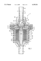
- FIG. 1 is a longitudinal section through the valve according to the invention
- FIG. 2 is a perspective representation of a valve seat body of the valve according to a first embodiment
- FIG. 3 is a bottom view of a valve seat body of the valve according to a second embodiment.
- the valve 1 schematically represented in the longitudinal section in FIG. 1 is used for the metered introduction of fuel evaporated from a fuel tank of an internal combustion engine into an intake tube of the engine and is part of a fuel evaporation retention system, not shown in detail, of a mixture-compressing internal combustion engine with externally supplied ignition.
- the design and the function of this kind of fuel evaporation retention systems can be taken, for example, from the Bosch Technical Instruction, Motormanagement Motronic [Motor Management & Motor Electronics], second edition, August 1993, pp. 48 and 49.
- valve 1 of this kind which is also called a regenerating valve or a tank ventilation valve, is furthermore known to one skilled in the art from the German Patent Disclosure 40 23 044, whose disclosure is intended to be a component of the current patent application.
- the valve 1 Coaxial to a valve longitudinal axis 2, the valve 1 has a two-part valve housing with a cylindrically stepped, sleeve-shaped lower housing part 4 and a cover-shaped upper housing part 5.
- the upper housing part 5, for example, is placed onto the lower housing part 4 and thereby engages the lower housing part 4 on its outer surface.
- Both housing parts 4, 5 are preferably comprised of plastic and are, for example, non-detachably connected, e.g. by means of ultrasonic welding or also detachably connected, e.g. by means of a detent connection.
- the lower housing part 4 has an inflow fitting 8 for connecting to a ventilation fitting, not shown, of a fuel tank of the engine or to an adsorption filter that follows the fuel tank.
- the adsorption filter is used in a known manner for temporarily storing evaporated fuel vapor from the fuel tank and is filled, for example, with activated charcoal.
- the upper housing part 5 has an outflow fitting 9 for connecting to an intake tube of the engine.
- the inflow fitting 8 and the outflow fitting 9 are respectively disposed axially in the housing parts 4 and 5, approximately flush with each other.
- An electromagnet 12 is disposed on the inside of the lower housing part 4. It has a cup-shaped magnet housing 14 with a coaxial, hollow cylindrical magnet core 15 that passes through a bottom 25 of the magnet housing 14, and a cylindrical excitation coil 16, which sits on a coil support 17 and rests in the magnet housing 14, encompassing the magnet core 15.
- An outwardly protruding threaded fitting 18 with an internal thread 19 is embodied of one piece at the bottom 25 of the magnet housing 14 and an externally threaded section 20 on the hollow cylindrical magnet core 15 is screwed into this internal thread.
- the magnet core 15 By turning the magnet core 15, it can be moved axially in the magnet housing 14 for adjustment purposes.
- the magnet core 15 has an axial through opening 21 that is defined by the hollow magnet core 15 so that fuel vapor in the through opening 21 can flow from the inflow fitting 8 to the outflow fitting 9.
- the magnet housing 14 with the magnet core 15 is inserted into the lower housing part 4 so that axial conduits 24 remain between an outer jacket 22 of the magnet housing 14 and an inner wall 23 of the lower housing part 4, and these axial conduits are offset from one another, for example in the circumference direction, by equal angles so that as shown in FIG. 1, for example, only two axial conduits 24 can be seen.
- the axial conduits 24 communicate with the inflow fitting 8 by way of an annular chamber 27 disposed in the lower housing part 4 between the bottom 25 of the magnet housing 14 and the inflow fitting 8 and on the other end, they communicate with the inside of the magnet housing 14 downstream of the excitation coil 16 by means of bores 28 that are let into the magnet housing 14 close to the open end of the magnet housing 14.
- the fuel vapor entering the inflow fitting 8 can also flow around the magnet housing 14 by means of these axial conduits 24 and can thus dissipate heat produced here.
- the magnet housing 14 has a curved rim 29, which is used as a support flange for a yoke-shaped valve seat body 31.
- the valve seat body 31 constitutes the magnetic yoke of the electromagnet 12.
- the valve seat body 31 partially covers the magnet housing 14 and is fastened to the lower housing part 4 by means of at least two alignment holes 47 depicted in FIGS. 2 and 3.
- the valve seat body 31 disposed on the rim 29 is thereby received in an elastic, annular bearing receptacle 32 with a U-shaped cross section, which for its part, is clamped between the two housing parts 4 and 5.
- a valve member 36 comprised of magnetic material simultaneously constitutes the armature of the electromagnet 12 and is fastened to a leaf spring 33, which is clamped on the rim end between the valve seat body 31 and the rim 29.
- the valve seat body 31 has at least one valve opening 34.
- two gap-shaped valve openings 34 are provided which, as shown in FIG. 2, have a semicircular shape, for example, and are disposed opposite each other so that they supplement each other to form an imaginary circular shape. It is, however, also possible, as depicted in FIG. 3, a top view of the valve seat body 31 embodied according to a second embodiment type, to embody the valve openings 34 in a U-shape, which can complement each other to form an imaginary rectangle.
- the two valve openings 34 can be closed by the valve member 36 so that a double valve seat 37 is produced.
- a through opening 38 is provided in the valve member 36 and extends coaxially in relation to the hollow cylindrical magnet core 15, and fuel flowing from the inflow fitting 8 by way of the through opening 21 of the magnet core 15 can flow by way of this through opening 38 into the outflow fitting 9 when the valve openings 34 are open.
- the valve member 36 is acted on in the valve closing direction toward the outflow fitting 9 by a valve closing spring 43, which is supported on the one end against the valve member 36 and on the other end, is supported against a sleeve-shaped end 41 of the magnet core 15.
- the valve member 36 On its end oriented toward the double valve seat 37, the valve member 36 has a seal 42 made of elastic material, for example elastomer.
- the seal 42 also lines the through opening 38 and protrudes slightly beyond a side of the valve member 36 remote from the double valve seat 37.
- the valve closing spring 43 presses the valve member 36 with the seal 42 onto the double valve seat 37 and thereby closes the valve openings 34.
- the valve member 36 When the electromagnet 12 is supplied with current, the valve member 36 is pressed with its seal 42, which protrudes from the through opening 38, against the end 41 of the magnet core 15, which forms a stop 44 for the stroke motion of the valve member 36.
- the stop 44 can be moved axially and as a result, the through flow quantity when the valve member 36 is maximally lifted from the double valve seat 37 can be determined.
- the valve closing spring 43 is weakly dimensioned since when there is a pressure drop between the outflow fitting 9 and the inflow fitting 8, a suction effect is exerted on the valve member 36 in the direction of closing the valve and the closing action of the valve closing spring 43 is encouraged.
- the electromagnet 12 is triggered cyclically by the control electronics of a control device that is not shown in detail, and a plug connection 50 for this purpose is provided on the upper housing part 5.
- the clock pulse rate is predetermined by the operating state of the engine so that the through flow quantity of evaporated fuel vapor traveling from the inflow fitting 8 into the outflow fitting 9 by way of valve openings 34 can be correspondingly metered.
- a sealing ring 51 rests against the side 49 of the valve seat body 31 oriented toward the outflow fitting 9 and seals an outer annular chamber 52 between the valve seat body 31 and the upper housing part 5 from an internal chamber 53 that is disposed in the outflow fitting 9 and communicates with the valve openings 34.
- the conduit that passes through the outflow fitting 9 is embodied in the form of a Laval nozzle 55, which is comprised in a known manner of a convergent part 56 and a divergent part 57.
- the Laval nozzle 55 tapers from a first entry cross section 60 in the downstream vicinity of the valve seat body 31, down to a narrowest cross section 61 and then from this narrowest cross section 61, widens to an end cross section 62 on the downstream end.
- the embodiment of the cross sections 60, 61, 62 is executed in such a way that the entry cross section 60 is at least equal to or greater than the end cross section 62.
- the entry cross section 60 is 1.1 to 2 times greater than the end cross section 62.
- the narrowest cross section 61 is preferably embodied as 2 to 4 times smaller than the entry cross section 60.
- the length of the Laval nozzle 55 measured between the entry cross section 60 and the end cross section 62 is for example 3 to 5 times greater than a diameter at the entry cross section 60.
- the side 49 of the valve seat body 31, in the direction of the valve longitudinal axis 2, has a spacing from the entry side of the outflow fitting 9 that has the entry cross section 60 so that an intermediary space 63 is formed between the side 49, the entry side of the outflow fitting 9, and the sealing ring 51, which has at least one lateral extension perpendicular to the valve longitudinal axis 2, that is as great as the diameter of the entry cross section 60 and the valve openings 34 feed into this intermediary space 63.
- valve member 36 Since only the two valve openings 34 of the valve seat body 31 have to be covered by the valve member 36 for the diversion, it is possible, by means of a simple change to the valve stroke of the valve member 36, to optimally adapt it to the narrowest cross section 61 of the Laval nozzle 55 without requiring a change in the dimensional ratios of the cross sections of the Laval nozzle 55 for this purpose.
- the cross sections of the two valve openings 34 are essentially embodied as smaller than an entry cross section 60 of the Laval nozzle 55.
- the two cross sections together amount to only approx. 10 to 20 percent of the entry cross section 60. Due to the relatively small cross section of the two valve openings 34, the interruption of the fuel flow by means of the valve member 36 can be carried out at a high speed so that a valve 1 can be produced that switches particularly rapidly.
- the adaptation to desired through flow quantities of the valve 1 is possible by means of a simple change to the valve stroke or by means of turning the magnet core 15 in the magnet housing 14.
Landscapes
- Engineering & Computer Science (AREA)
- Chemical & Material Sciences (AREA)
- Combustion & Propulsion (AREA)
- Mechanical Engineering (AREA)
- General Engineering & Computer Science (AREA)
- Magnetically Actuated Valves (AREA)
Applications Claiming Priority (3)
| Application Number | Priority Date | Filing Date | Title |
|---|---|---|---|
| DE19721562A DE19721562A1 (de) | 1997-05-23 | 1997-05-23 | Ventil zum dosierten Einleiten von verflüchtigtem Brennstoff |
| DE19721562 | 1997-05-23 | ||
| PCT/DE1998/000472 WO1998053195A1 (de) | 1997-05-23 | 1998-02-18 | Ventil zum dosierten einleiten von verflüchtigtem brennstoff |
Publications (1)
| Publication Number | Publication Date |
|---|---|
| US6149126A true US6149126A (en) | 2000-11-21 |
Family
ID=7830256
Family Applications (1)
| Application Number | Title | Priority Date | Filing Date |
|---|---|---|---|
| US09/230,360 Expired - Fee Related US6149126A (en) | 1997-05-23 | 1998-02-18 | Valve for the metered introduction of evaporated fuel |
Country Status (8)
| Country | Link |
|---|---|
| US (1) | US6149126A (de) |
| EP (1) | EP0914552B1 (de) |
| JP (1) | JP2000515606A (de) |
| KR (1) | KR20000029436A (de) |
| BR (1) | BR9804944A (de) |
| DE (2) | DE19721562A1 (de) |
| RU (1) | RU2195571C2 (de) |
| WO (1) | WO1998053195A1 (de) |
Cited By (20)
| Publication number | Priority date | Publication date | Assignee | Title |
|---|---|---|---|---|
| US6253789B1 (en) * | 1998-08-29 | 2001-07-03 | Robert Bosch Gmbh | Valve for metered introduction of volatilized fuel |
| US6415817B1 (en) * | 1999-01-14 | 2002-07-09 | Robert Bosch Gmbh | Valve for dosing the admission of volatilized fuel |
| US6450152B1 (en) * | 2001-06-15 | 2002-09-17 | Siemens Automotive Inc. | Low-profile fuel tank isolation valve |
| US6530558B1 (en) * | 1999-07-27 | 2003-03-11 | Robert Bosch Gmbh | Valve for metered introduction of evaporated fuel into an intake conduit of an internal combustion engine |
| US6548837B1 (en) * | 1999-06-08 | 2003-04-15 | Johnson Controls Automotive Electronics | Solenoid bleed valve for a device for the disposal of vapours |
| EP1314880A1 (de) * | 2001-11-15 | 2003-05-28 | Carl Freudenberg KG | Regenerierventil für eine Tankentlüftungsanlage |
| US20040255916A1 (en) * | 2003-04-04 | 2004-12-23 | Kirk Ivens | Permanent magnet digital purge valve |
| WO2004113712A3 (en) * | 2003-06-20 | 2005-03-17 | Siemens Vdo Automotive Inc | Purge valve including a permanent magnet linear actuator |
| WO2005064149A1 (de) * | 2003-12-23 | 2005-07-14 | Robert Bosch Gmbh | Brennstoffeinspritzventil |
| CN1295431C (zh) * | 2004-01-02 | 2007-01-17 | 沈开华 | 发动机多功能数码滤清器 |
| US20080000456A1 (en) * | 2006-06-30 | 2008-01-03 | Siemens Canada Limited | Cost-optimized canister purge valve |
| US20080061082A1 (en) * | 2005-02-15 | 2008-03-13 | Reckitt Benckiser (Uk) Limited | Holder for a Spray Container |
| US20080099483A1 (en) * | 2005-02-15 | 2008-05-01 | Reckitt Benckiser (Uk) Limited | Seal Assembly for a Pressurised Container |
| US20080156896A1 (en) * | 2005-02-15 | 2008-07-03 | Reckitt Benckiser (Uk) Limited | Spray Device |
| US20080272208A1 (en) * | 2005-10-18 | 2008-11-06 | Reckitt Benckiser (Uk) Limited | Spraying Device |
| US20100140298A1 (en) * | 2006-11-18 | 2010-06-10 | Reckitt Benckiser (Uk) Limited | Dispensing Device, Refill Cartridge and Jacket Assembly |
| US20120001108A1 (en) * | 2009-02-20 | 2012-01-05 | Xiamen Koge Micro Tech Co., Ltd. | Electromagnetic linear valve |
| US20160090945A1 (en) * | 2014-09-25 | 2016-03-31 | Denso Corporation | Two-stage changeover valve |
| US11054040B2 (en) * | 2018-07-18 | 2021-07-06 | Mikuni Corporation | Electromagnetic valve |
| US20240175514A1 (en) * | 2022-11-24 | 2024-05-30 | Hydrotek Corporation | Solenoid valve |
Families Citing this family (6)
| Publication number | Priority date | Publication date | Assignee | Title |
|---|---|---|---|---|
| FR2788324A1 (fr) * | 1999-01-08 | 2000-07-13 | Sagem | Siege de clapet d'electrovanne |
| DE19928207A1 (de) * | 1999-06-19 | 2000-12-21 | Bosch Gmbh Robert | Magnetventil |
| ES2167275B1 (es) * | 2000-10-20 | 2003-10-16 | Bitron Ind Espana Sa | Electrovalvula reguladora de caudal de aire. |
| JP2005155712A (ja) * | 2003-11-21 | 2005-06-16 | Mitsubishi Electric Corp | 電磁弁 |
| JP4166779B2 (ja) * | 2005-11-28 | 2008-10-15 | 三菱電機株式会社 | 内燃機関制御装置 |
| JP5414088B2 (ja) * | 2008-06-17 | 2014-02-12 | サンデン株式会社 | 圧縮機 |
Citations (9)
| Publication number | Priority date | Publication date | Assignee | Title |
|---|---|---|---|---|
| US4763635A (en) * | 1985-05-30 | 1988-08-16 | Robert Bosch Gmbh | Discharge system for introducing volatilized fuel into an internal combustion engine |
| US4901702A (en) * | 1988-01-29 | 1990-02-20 | Firma Carl Freudenberg | Apparatus for the measured feeding of volatile fuel components to the intake tube of an internal combustion engine |
| US4986246A (en) * | 1988-12-31 | 1991-01-22 | Robert Bosch Gmbh | Valve for the metered admixture of volatilized fuel to the fuel-air mixture of an internal combustion engine |
| US5178116A (en) * | 1990-07-20 | 1993-01-12 | Robert Bosch Gmbh | Valve for metered admixing of volatilized fuel to the fuel/air mixture of an internal combustion engine |
| US5188141A (en) * | 1991-12-03 | 1993-02-23 | Siemens Automotive Limited | Vacuum boost valve |
| US5269278A (en) * | 1991-12-04 | 1993-12-14 | Firma Carl Freudenberg | Device for storing and feeding fuel vapors |
| US5460137A (en) * | 1992-09-01 | 1995-10-24 | Firma Carl Freudenberg | Apparatus for the temporary storage and controlled feeding of volatile fuel components to an internal combustion engine |
| US5560585A (en) * | 1992-12-24 | 1996-10-01 | Robert Bosch Gmbh | Valve for metering introduction of evaporated fuel into an induction duct of an internal combustion engine |
| US5630403A (en) * | 1996-06-13 | 1997-05-20 | Siemens Electric Limited | Force-balanced sonic flow emission control valve |
Family Cites Families (1)
| Publication number | Priority date | Publication date | Assignee | Title |
|---|---|---|---|---|
| JPS62110087A (ja) * | 1985-11-06 | 1987-05-21 | Aisin Seiki Co Ltd | 切替弁装置 |
-
1997
- 1997-05-23 DE DE19721562A patent/DE19721562A1/de not_active Withdrawn
-
1998
- 1998-02-18 DE DE59808243T patent/DE59808243D1/de not_active Expired - Fee Related
- 1998-02-18 JP JP10549767A patent/JP2000515606A/ja not_active Abandoned
- 1998-02-18 WO PCT/DE1998/000472 patent/WO1998053195A1/de not_active Ceased
- 1998-02-18 BR BR9804944A patent/BR9804944A/pt not_active IP Right Cessation
- 1998-02-18 US US09/230,360 patent/US6149126A/en not_active Expired - Fee Related
- 1998-02-18 RU RU99103122/06A patent/RU2195571C2/ru not_active IP Right Cessation
- 1998-02-18 EP EP98912262A patent/EP0914552B1/de not_active Expired - Lifetime
- 1998-02-18 KR KR1019997000379A patent/KR20000029436A/ko not_active Withdrawn
Patent Citations (9)
| Publication number | Priority date | Publication date | Assignee | Title |
|---|---|---|---|---|
| US4763635A (en) * | 1985-05-30 | 1988-08-16 | Robert Bosch Gmbh | Discharge system for introducing volatilized fuel into an internal combustion engine |
| US4901702A (en) * | 1988-01-29 | 1990-02-20 | Firma Carl Freudenberg | Apparatus for the measured feeding of volatile fuel components to the intake tube of an internal combustion engine |
| US4986246A (en) * | 1988-12-31 | 1991-01-22 | Robert Bosch Gmbh | Valve for the metered admixture of volatilized fuel to the fuel-air mixture of an internal combustion engine |
| US5178116A (en) * | 1990-07-20 | 1993-01-12 | Robert Bosch Gmbh | Valve for metered admixing of volatilized fuel to the fuel/air mixture of an internal combustion engine |
| US5188141A (en) * | 1991-12-03 | 1993-02-23 | Siemens Automotive Limited | Vacuum boost valve |
| US5269278A (en) * | 1991-12-04 | 1993-12-14 | Firma Carl Freudenberg | Device for storing and feeding fuel vapors |
| US5460137A (en) * | 1992-09-01 | 1995-10-24 | Firma Carl Freudenberg | Apparatus for the temporary storage and controlled feeding of volatile fuel components to an internal combustion engine |
| US5560585A (en) * | 1992-12-24 | 1996-10-01 | Robert Bosch Gmbh | Valve for metering introduction of evaporated fuel into an induction duct of an internal combustion engine |
| US5630403A (en) * | 1996-06-13 | 1997-05-20 | Siemens Electric Limited | Force-balanced sonic flow emission control valve |
Cited By (27)
| Publication number | Priority date | Publication date | Assignee | Title |
|---|---|---|---|---|
| US6253789B1 (en) * | 1998-08-29 | 2001-07-03 | Robert Bosch Gmbh | Valve for metered introduction of volatilized fuel |
| US6415817B1 (en) * | 1999-01-14 | 2002-07-09 | Robert Bosch Gmbh | Valve for dosing the admission of volatilized fuel |
| US6548837B1 (en) * | 1999-06-08 | 2003-04-15 | Johnson Controls Automotive Electronics | Solenoid bleed valve for a device for the disposal of vapours |
| US6530558B1 (en) * | 1999-07-27 | 2003-03-11 | Robert Bosch Gmbh | Valve for metered introduction of evaporated fuel into an intake conduit of an internal combustion engine |
| US6450152B1 (en) * | 2001-06-15 | 2002-09-17 | Siemens Automotive Inc. | Low-profile fuel tank isolation valve |
| EP1314880A1 (de) * | 2001-11-15 | 2003-05-28 | Carl Freudenberg KG | Regenerierventil für eine Tankentlüftungsanlage |
| US20040255916A1 (en) * | 2003-04-04 | 2004-12-23 | Kirk Ivens | Permanent magnet digital purge valve |
| US7086383B2 (en) | 2003-04-04 | 2006-08-08 | Siemens Vdo Automotive Inc. | Permanent magnet digital purge valve |
| WO2004113712A3 (en) * | 2003-06-20 | 2005-03-17 | Siemens Vdo Automotive Inc | Purge valve including a permanent magnet linear actuator |
| WO2005064149A1 (de) * | 2003-12-23 | 2005-07-14 | Robert Bosch Gmbh | Brennstoffeinspritzventil |
| CN1295431C (zh) * | 2004-01-02 | 2007-01-17 | 沈开华 | 发动机多功能数码滤清器 |
| US20080061082A1 (en) * | 2005-02-15 | 2008-03-13 | Reckitt Benckiser (Uk) Limited | Holder for a Spray Container |
| US20100237108A1 (en) * | 2005-02-15 | 2010-09-23 | Reckitt Benckiser (Uk) Limited | Spray Device |
| US20080099483A1 (en) * | 2005-02-15 | 2008-05-01 | Reckitt Benckiser (Uk) Limited | Seal Assembly for a Pressurised Container |
| US20080156896A1 (en) * | 2005-02-15 | 2008-07-03 | Reckitt Benckiser (Uk) Limited | Spray Device |
| US8814008B2 (en) | 2005-02-15 | 2014-08-26 | Reckitt Benckiser (Uk) Limited | Seal assembly for a pressurised container |
| US8079498B2 (en) | 2005-02-15 | 2011-12-20 | Reckitt Benckiser (Uk) Limited | Holder for a spray container |
| US20080272208A1 (en) * | 2005-10-18 | 2008-11-06 | Reckitt Benckiser (Uk) Limited | Spraying Device |
| US20080000456A1 (en) * | 2006-06-30 | 2008-01-03 | Siemens Canada Limited | Cost-optimized canister purge valve |
| US20100140298A1 (en) * | 2006-11-18 | 2010-06-10 | Reckitt Benckiser (Uk) Limited | Dispensing Device, Refill Cartridge and Jacket Assembly |
| US20120001108A1 (en) * | 2009-02-20 | 2012-01-05 | Xiamen Koge Micro Tech Co., Ltd. | Electromagnetic linear valve |
| US9068663B2 (en) * | 2009-02-20 | 2015-06-30 | Xiamen Koge Micro Tech Co., Ltd. | Electromagnetic linear valve |
| US20160090945A1 (en) * | 2014-09-25 | 2016-03-31 | Denso Corporation | Two-stage changeover valve |
| US9840986B2 (en) * | 2014-09-25 | 2017-12-12 | Denso Corporation | Two-stage changeover valve |
| US11054040B2 (en) * | 2018-07-18 | 2021-07-06 | Mikuni Corporation | Electromagnetic valve |
| US20240175514A1 (en) * | 2022-11-24 | 2024-05-30 | Hydrotek Corporation | Solenoid valve |
| US12404948B2 (en) * | 2022-11-24 | 2025-09-02 | Hydrotek Corporation | Solenoid valve |
Also Published As
| Publication number | Publication date |
|---|---|
| EP0914552B1 (de) | 2003-05-07 |
| KR20000029436A (ko) | 2000-05-25 |
| EP0914552A1 (de) | 1999-05-12 |
| BR9804944A (pt) | 1999-08-24 |
| DE19721562A1 (de) | 1998-11-26 |
| RU2195571C2 (ru) | 2002-12-27 |
| DE59808243D1 (de) | 2003-06-12 |
| WO1998053195A1 (de) | 1998-11-26 |
| JP2000515606A (ja) | 2000-11-21 |
Similar Documents
| Publication | Publication Date | Title |
|---|---|---|
| US6149126A (en) | Valve for the metered introduction of evaporated fuel | |
| EP0740741B2 (de) | Abführungssystem mit abführungsventil für einen behälter | |
| US4395988A (en) | Fuel injection system | |
| US5809977A (en) | Valve for metered introduction of volatilized fuel | |
| US5657962A (en) | Solenoid valve closure part and recycling circuit for the petrol vapours of internal combustion engines | |
| US5901742A (en) | Pressure control valve | |
| US5927322A (en) | Quantity regulating valve for controlling liquids | |
| US5878991A (en) | Magnet valve for fuel tank ventilation | |
| US5765538A (en) | Pump device for a fuel vapor retention system of an internal combustion engine | |
| US5791318A (en) | Valve for the metered introduction of fuel vapor evaporated from a fuel tank of an internal combustion engine | |
| US4394973A (en) | Injection valve | |
| US4421278A (en) | Injection valve | |
| US6253789B1 (en) | Valve for metered introduction of volatilized fuel | |
| US5769328A (en) | Fuel interconnect for fuel injector | |
| US6415817B1 (en) | Valve for dosing the admission of volatilized fuel | |
| US7712453B2 (en) | Depressurizing valve and fuel injection device | |
| EP0971124A3 (de) | Filter für Brennstoffeinspritzdüse | |
| JPH076461B2 (ja) | 気化燃料を内燃機関内に案内するための排出装置 | |
| US5823444A (en) | Fuel injection valve | |
| US6321725B1 (en) | Valve for metered introduction of evaporated fuel | |
| JP2016065526A (ja) | 二段切替弁 | |
| CZ292331B6 (cs) | Ventilové zařízení | |
| JPS58163881A (ja) | 電磁弁 | |
| KR20010072485A (ko) | 솔레노이드 밸브 | |
| US4317542A (en) | Fuel injector |
Legal Events
| Date | Code | Title | Description |
|---|---|---|---|
| AS | Assignment |
Owner name: ROBERT BOSCH GMBH, GERMANY Free format text: ASSIGNMENT OF ASSIGNORS INTEREST;ASSIGNORS:KRIMMER, ERWIN;SCHULZ, WOLFGANG;MIEHLE, TILMAN;AND OTHERS;REEL/FRAME:009904/0888 Effective date: 19990119 |
|
| FEPP | Fee payment procedure |
Free format text: PAYOR NUMBER ASSIGNED (ORIGINAL EVENT CODE: ASPN); ENTITY STATUS OF PATENT OWNER: LARGE ENTITY |
|
| FPAY | Fee payment |
Year of fee payment: 4 |
|
| REMI | Maintenance fee reminder mailed | ||
| LAPS | Lapse for failure to pay maintenance fees | ||
| STCH | Information on status: patent discontinuation |
Free format text: PATENT EXPIRED DUE TO NONPAYMENT OF MAINTENANCE FEES UNDER 37 CFR 1.362 |
|
| FP | Lapsed due to failure to pay maintenance fee |
Effective date: 20081121 |