US6149714A - Process for enriched combustion using solid electrolyte ionic conductor systems - Google Patents
Process for enriched combustion using solid electrolyte ionic conductor systems Download PDFInfo
- Publication number
- US6149714A US6149714A US09/280,340 US28034099A US6149714A US 6149714 A US6149714 A US 6149714A US 28034099 A US28034099 A US 28034099A US 6149714 A US6149714 A US 6149714A
- Authority
- US
- United States
- Prior art keywords
- oxygen
- gas stream
- stream
- ion transport
- combustion
- Prior art date
- Legal status (The legal status is an assumption and is not a legal conclusion. Google has not performed a legal analysis and makes no representation as to the accuracy of the status listed.)
- Expired - Lifetime
Links
- 238000002485 combustion reaction Methods 0.000 title claims abstract description 114
- 238000000034 method Methods 0.000 title abstract description 59
- 230000008569 process Effects 0.000 title abstract description 54
- 239000010416 ion conductor Substances 0.000 title description 12
- 239000007784 solid electrolyte Substances 0.000 title description 10
- 239000007789 gas Substances 0.000 claims abstract description 257
- 239000001301 oxygen Substances 0.000 claims abstract description 215
- 229910052760 oxygen Inorganic materials 0.000 claims abstract description 215
- QVGXLLKOCUKJST-UHFFFAOYSA-N atomic oxygen Chemical compound [O] QVGXLLKOCUKJST-UHFFFAOYSA-N 0.000 claims abstract description 207
- 230000037427 ion transport Effects 0.000 claims abstract description 150
- 239000012528 membrane Substances 0.000 claims abstract description 128
- IJGRMHOSHXDMSA-UHFFFAOYSA-N Atomic nitrogen Chemical compound N#N IJGRMHOSHXDMSA-UHFFFAOYSA-N 0.000 claims abstract description 125
- 239000012466 permeate Substances 0.000 claims abstract description 101
- 239000012465 retentate Substances 0.000 claims abstract description 61
- 229910052757 nitrogen Inorganic materials 0.000 claims abstract description 60
- 238000010926 purge Methods 0.000 claims abstract description 53
- 239000000446 fuel Substances 0.000 claims abstract description 50
- 239000000047 product Substances 0.000 claims abstract description 37
- 230000001590 oxidative effect Effects 0.000 claims abstract description 23
- 239000007800 oxidant agent Substances 0.000 claims abstract description 22
- MYMOFIZGZYHOMD-UHFFFAOYSA-N Dioxygen Chemical compound O=O MYMOFIZGZYHOMD-UHFFFAOYSA-N 0.000 claims abstract description 7
- 230000000779 depleting effect Effects 0.000 claims abstract description 5
- 229910001882 dioxygen Inorganic materials 0.000 claims abstract description 5
- UGFAIRIUMAVXCW-UHFFFAOYSA-N Carbon monoxide Chemical compound [O+]#[C-] UGFAIRIUMAVXCW-UHFFFAOYSA-N 0.000 claims description 53
- 239000003546 flue gas Substances 0.000 claims description 48
- XLYOFNOQVPJJNP-UHFFFAOYSA-N water Substances O XLYOFNOQVPJJNP-UHFFFAOYSA-N 0.000 claims description 18
- 238000010438 heat treatment Methods 0.000 claims description 16
- 238000012546 transfer Methods 0.000 claims description 12
- CURLTUGMZLYLDI-UHFFFAOYSA-N Carbon dioxide Chemical compound O=C=O CURLTUGMZLYLDI-UHFFFAOYSA-N 0.000 claims description 10
- 229910002092 carbon dioxide Inorganic materials 0.000 claims description 6
- 238000001816 cooling Methods 0.000 claims description 6
- 229910001873 dinitrogen Inorganic materials 0.000 claims description 5
- 239000001569 carbon dioxide Substances 0.000 claims description 4
- 238000003303 reheating Methods 0.000 claims description 4
- 230000003134 recirculating effect Effects 0.000 claims 2
- 230000003647 oxidation Effects 0.000 abstract description 7
- 238000007254 oxidation reaction Methods 0.000 abstract description 7
- 238000006243 chemical reaction Methods 0.000 abstract description 4
- 239000003570 air Substances 0.000 description 61
- 239000000203 mixture Substances 0.000 description 23
- MWUXSHHQAYIFBG-UHFFFAOYSA-N nitrogen oxide Inorganic materials O=[N] MWUXSHHQAYIFBG-UHFFFAOYSA-N 0.000 description 23
- 238000011143 downstream manufacturing Methods 0.000 description 21
- 239000002737 fuel gas Substances 0.000 description 21
- UFHFLCQGNIYNRP-UHFFFAOYSA-N Hydrogen Chemical compound [H][H] UFHFLCQGNIYNRP-UHFFFAOYSA-N 0.000 description 15
- 239000000463 material Substances 0.000 description 15
- 239000002912 waste gas Substances 0.000 description 15
- 238000000926 separation method Methods 0.000 description 11
- 230000008901 benefit Effects 0.000 description 10
- 230000004907 flux Effects 0.000 description 10
- 238000004519 manufacturing process Methods 0.000 description 10
- 238000010586 diagram Methods 0.000 description 9
- 230000010354 integration Effects 0.000 description 9
- -1 oxygen ions Chemical class 0.000 description 9
- 230000032258 transport Effects 0.000 description 9
- 239000000919 ceramic Substances 0.000 description 8
- 150000002500 ions Chemical class 0.000 description 8
- MRELNEQAGSRDBK-UHFFFAOYSA-N lanthanum(3+);oxygen(2-) Chemical compound [O-2].[O-2].[O-2].[La+3].[La+3] MRELNEQAGSRDBK-UHFFFAOYSA-N 0.000 description 8
- 239000011533 mixed conductor Substances 0.000 description 8
- IATRAKWUXMZMIY-UHFFFAOYSA-N strontium oxide Chemical compound [O-2].[Sr+2] IATRAKWUXMZMIY-UHFFFAOYSA-N 0.000 description 8
- 229910002091 carbon monoxide Inorganic materials 0.000 description 7
- 229910000428 cobalt oxide Inorganic materials 0.000 description 6
- IVMYJDGYRUAWML-UHFFFAOYSA-N cobalt(ii) oxide Chemical compound [Co]=O IVMYJDGYRUAWML-UHFFFAOYSA-N 0.000 description 6
- 230000009467 reduction Effects 0.000 description 6
- 230000015572 biosynthetic process Effects 0.000 description 5
- 238000005516 engineering process Methods 0.000 description 5
- 238000011084 recovery Methods 0.000 description 5
- 238000011144 upstream manufacturing Methods 0.000 description 5
- XKRFYHLGVUSROY-UHFFFAOYSA-N Argon Chemical compound [Ar] XKRFYHLGVUSROY-UHFFFAOYSA-N 0.000 description 4
- 229910052747 lanthanoid Inorganic materials 0.000 description 4
- 150000002602 lanthanoids Chemical class 0.000 description 4
- 229910052751 metal Inorganic materials 0.000 description 4
- 239000002184 metal Substances 0.000 description 4
- VNWKTOKETHGBQD-UHFFFAOYSA-N methane Chemical compound C VNWKTOKETHGBQD-UHFFFAOYSA-N 0.000 description 4
- 238000001179 sorption measurement Methods 0.000 description 4
- 229910052712 strontium Inorganic materials 0.000 description 4
- 229910000416 bismuth oxide Inorganic materials 0.000 description 3
- 230000003197 catalytic effect Effects 0.000 description 3
- 229910000420 cerium oxide Inorganic materials 0.000 description 3
- 239000002131 composite material Substances 0.000 description 3
- 238000010276 construction Methods 0.000 description 3
- 229910052802 copper Inorganic materials 0.000 description 3
- 238000013461 design Methods 0.000 description 3
- TYIXMATWDRGMPF-UHFFFAOYSA-N dibismuth;oxygen(2-) Chemical compound [O-2].[O-2].[O-2].[Bi+3].[Bi+3] TYIXMATWDRGMPF-UHFFFAOYSA-N 0.000 description 3
- 230000000694 effects Effects 0.000 description 3
- 229910052742 iron Inorganic materials 0.000 description 3
- 238000002844 melting Methods 0.000 description 3
- 230000008018 melting Effects 0.000 description 3
- 238000002156 mixing Methods 0.000 description 3
- 238000012986 modification Methods 0.000 description 3
- 230000004048 modification Effects 0.000 description 3
- BMMGVYCKOGBVEV-UHFFFAOYSA-N oxo(oxoceriooxy)cerium Chemical compound [Ce]=O.O=[Ce]=O BMMGVYCKOGBVEV-UHFFFAOYSA-N 0.000 description 3
- 229910052697 platinum Inorganic materials 0.000 description 3
- 238000010248 power generation Methods 0.000 description 3
- 239000007787 solid Substances 0.000 description 3
- 239000002699 waste material Substances 0.000 description 3
- OKTJSMMVPCPJKN-UHFFFAOYSA-N Carbon Chemical compound [C] OKTJSMMVPCPJKN-UHFFFAOYSA-N 0.000 description 2
- 229910052786 argon Inorganic materials 0.000 description 2
- 229910052797 bismuth Inorganic materials 0.000 description 2
- WUKWITHWXAAZEY-UHFFFAOYSA-L calcium difluoride Chemical compound [F-].[F-].[Ca+2] WUKWITHWXAAZEY-UHFFFAOYSA-L 0.000 description 2
- 229910052799 carbon Inorganic materials 0.000 description 2
- 230000006835 compression Effects 0.000 description 2
- 238000007906 compression Methods 0.000 description 2
- 230000007423 decrease Effects 0.000 description 2
- 238000011161 development Methods 0.000 description 2
- 239000010436 fluorite Substances 0.000 description 2
- 239000011521 glass Substances 0.000 description 2
- 230000020169 heat generation Effects 0.000 description 2
- 229910052739 hydrogen Inorganic materials 0.000 description 2
- 239000001257 hydrogen Substances 0.000 description 2
- 230000006872 improvement Effects 0.000 description 2
- 229910052809 inorganic oxide Inorganic materials 0.000 description 2
- 229910052746 lanthanum Inorganic materials 0.000 description 2
- 150000002739 metals Chemical class 0.000 description 2
- 239000003345 natural gas Substances 0.000 description 2
- 229910052759 nickel Inorganic materials 0.000 description 2
- 238000005457 optimization Methods 0.000 description 2
- 229910052574 oxide ceramic Inorganic materials 0.000 description 2
- 239000003208 petroleum Substances 0.000 description 2
- 238000011160 research Methods 0.000 description 2
- 229910052709 silver Inorganic materials 0.000 description 2
- 239000000126 substance Substances 0.000 description 2
- 239000000758 substrate Substances 0.000 description 2
- 229910052715 tantalum Inorganic materials 0.000 description 2
- 229910052719 titanium Inorganic materials 0.000 description 2
- 229910052726 zirconium Inorganic materials 0.000 description 2
- 101150058765 BACE1 gene Proteins 0.000 description 1
- 229910052691 Erbium Inorganic materials 0.000 description 1
- 229910020785 La—Ce Inorganic materials 0.000 description 1
- WHXSMMKQMYFTQS-UHFFFAOYSA-N Lithium Chemical compound [Li] WHXSMMKQMYFTQS-UHFFFAOYSA-N 0.000 description 1
- 229910052765 Lutetium Inorganic materials 0.000 description 1
- 229910052779 Neodymium Inorganic materials 0.000 description 1
- CBENFWSGALASAD-UHFFFAOYSA-N Ozone Chemical compound [O-][O+]=O CBENFWSGALASAD-UHFFFAOYSA-N 0.000 description 1
- 229910052777 Praseodymium Inorganic materials 0.000 description 1
- 229910052772 Samarium Inorganic materials 0.000 description 1
- BQCADISMDOOEFD-UHFFFAOYSA-N Silver Chemical compound [Ag] BQCADISMDOOEFD-UHFFFAOYSA-N 0.000 description 1
- 229910000831 Steel Inorganic materials 0.000 description 1
- 229910052771 Terbium Inorganic materials 0.000 description 1
- 229910052776 Thorium Inorganic materials 0.000 description 1
- 229910052775 Thulium Inorganic materials 0.000 description 1
- 229910052769 Ytterbium Inorganic materials 0.000 description 1
- QCWXUUIWCKQGHC-UHFFFAOYSA-N Zirconium Chemical compound [Zr] QCWXUUIWCKQGHC-UHFFFAOYSA-N 0.000 description 1
- 229910052784 alkaline earth metal Inorganic materials 0.000 description 1
- 150000001342 alkaline earth metals Chemical class 0.000 description 1
- 229910052782 aluminium Inorganic materials 0.000 description 1
- XAGFODPZIPBFFR-UHFFFAOYSA-N aluminium Chemical compound [Al] XAGFODPZIPBFFR-UHFFFAOYSA-N 0.000 description 1
- 239000012080 ambient air Substances 0.000 description 1
- 238000004458 analytical method Methods 0.000 description 1
- 238000000137 annealing Methods 0.000 description 1
- 230000009286 beneficial effect Effects 0.000 description 1
- JCXGWMGPZLAOME-UHFFFAOYSA-N bismuth atom Chemical compound [Bi] JCXGWMGPZLAOME-UHFFFAOYSA-N 0.000 description 1
- 239000006227 byproduct Substances 0.000 description 1
- 229910052791 calcium Inorganic materials 0.000 description 1
- 229910010293 ceramic material Inorganic materials 0.000 description 1
- 229910052804 chromium Inorganic materials 0.000 description 1
- 238000009841 combustion method Methods 0.000 description 1
- 239000004020 conductor Substances 0.000 description 1
- 238000005336 cracking Methods 0.000 description 1
- 239000013078 crystal Substances 0.000 description 1
- 230000001419 dependent effect Effects 0.000 description 1
- 230000001627 detrimental effect Effects 0.000 description 1
- 239000003085 diluting agent Substances 0.000 description 1
- 238000004821 distillation Methods 0.000 description 1
- 230000009977 dual effect Effects 0.000 description 1
- 238000011234 economic evaluation Methods 0.000 description 1
- 239000003792 electrolyte Substances 0.000 description 1
- 239000003344 environmental pollutant Substances 0.000 description 1
- 238000000605 extraction Methods 0.000 description 1
- 239000010408 film Substances 0.000 description 1
- 239000012530 fluid Substances 0.000 description 1
- 229910052737 gold Inorganic materials 0.000 description 1
- 229910052735 hafnium Inorganic materials 0.000 description 1
- 229910052738 indium Inorganic materials 0.000 description 1
- 230000008595 infiltration Effects 0.000 description 1
- 238000001764 infiltration Methods 0.000 description 1
- 238000009434 installation Methods 0.000 description 1
- 229910052745 lead Inorganic materials 0.000 description 1
- 239000007788 liquid Substances 0.000 description 1
- 229910052744 lithium Inorganic materials 0.000 description 1
- 229910052748 manganese Inorganic materials 0.000 description 1
- 238000013178 mathematical model Methods 0.000 description 1
- 229910044991 metal oxide Inorganic materials 0.000 description 1
- 150000004706 metal oxides Chemical class 0.000 description 1
- 229910003455 mixed metal oxide Inorganic materials 0.000 description 1
- 229910052758 niobium Inorganic materials 0.000 description 1
- 229920000620 organic polymer Polymers 0.000 description 1
- 125000004430 oxygen atom Chemical group O* 0.000 description 1
- 229910052763 palladium Inorganic materials 0.000 description 1
- 230000000737 periodic effect Effects 0.000 description 1
- 231100000719 pollutant Toxicity 0.000 description 1
- 238000012545 processing Methods 0.000 description 1
- 230000009257 reactivity Effects 0.000 description 1
- 229910052707 ruthenium Inorganic materials 0.000 description 1
- 239000004332 silver Substances 0.000 description 1
- 239000010959 steel Substances 0.000 description 1
- 238000010408 sweeping Methods 0.000 description 1
- 230000002195 synergetic effect Effects 0.000 description 1
- 239000010409 thin film Substances 0.000 description 1
- 229910052718 tin Inorganic materials 0.000 description 1
- 229910052723 transition metal Inorganic materials 0.000 description 1
- 150000003624 transition metals Chemical class 0.000 description 1
- 229910052721 tungsten Inorganic materials 0.000 description 1
- 229910052720 vanadium Inorganic materials 0.000 description 1
- 239000006200 vaporizer Substances 0.000 description 1
- 229910052727 yttrium Inorganic materials 0.000 description 1
Images

Classifications
-
- B—PERFORMING OPERATIONS; TRANSPORTING
- B01—PHYSICAL OR CHEMICAL PROCESSES OR APPARATUS IN GENERAL
- B01D—SEPARATION
- B01D53/00—Separation of gases or vapours; Recovering vapours of volatile solvents from gases; Chemical or biological purification of waste gases, e.g. engine exhaust gases, smoke, fumes, flue gases, aerosols
- B01D53/32—Separation of gases or vapours; Recovering vapours of volatile solvents from gases; Chemical or biological purification of waste gases, e.g. engine exhaust gases, smoke, fumes, flue gases, aerosols by electrical effects other than those provided for in group B01D61/00
- B01D53/326—Separation of gases or vapours; Recovering vapours of volatile solvents from gases; Chemical or biological purification of waste gases, e.g. engine exhaust gases, smoke, fumes, flue gases, aerosols by electrical effects other than those provided for in group B01D61/00 in electrochemical cells
-
- B—PERFORMING OPERATIONS; TRANSPORTING
- B01—PHYSICAL OR CHEMICAL PROCESSES OR APPARATUS IN GENERAL
- B01D—SEPARATION
- B01D53/00—Separation of gases or vapours; Recovering vapours of volatile solvents from gases; Chemical or biological purification of waste gases, e.g. engine exhaust gases, smoke, fumes, flue gases, aerosols
- B01D53/22—Separation of gases or vapours; Recovering vapours of volatile solvents from gases; Chemical or biological purification of waste gases, e.g. engine exhaust gases, smoke, fumes, flue gases, aerosols by diffusion
-
- B—PERFORMING OPERATIONS; TRANSPORTING
- B01—PHYSICAL OR CHEMICAL PROCESSES OR APPARATUS IN GENERAL
- B01D—SEPARATION
- B01D53/00—Separation of gases or vapours; Recovering vapours of volatile solvents from gases; Chemical or biological purification of waste gases, e.g. engine exhaust gases, smoke, fumes, flue gases, aerosols
- B01D53/22—Separation of gases or vapours; Recovering vapours of volatile solvents from gases; Chemical or biological purification of waste gases, e.g. engine exhaust gases, smoke, fumes, flue gases, aerosols by diffusion
- B01D53/228—Separation of gases or vapours; Recovering vapours of volatile solvents from gases; Chemical or biological purification of waste gases, e.g. engine exhaust gases, smoke, fumes, flue gases, aerosols by diffusion characterised by specific membranes
-
- B—PERFORMING OPERATIONS; TRANSPORTING
- B01—PHYSICAL OR CHEMICAL PROCESSES OR APPARATUS IN GENERAL
- B01D—SEPARATION
- B01D53/00—Separation of gases or vapours; Recovering vapours of volatile solvents from gases; Chemical or biological purification of waste gases, e.g. engine exhaust gases, smoke, fumes, flue gases, aerosols
- B01D53/32—Separation of gases or vapours; Recovering vapours of volatile solvents from gases; Chemical or biological purification of waste gases, e.g. engine exhaust gases, smoke, fumes, flue gases, aerosols by electrical effects other than those provided for in group B01D61/00
-
- C—CHEMISTRY; METALLURGY
- C01—INORGANIC CHEMISTRY
- C01B—NON-METALLIC ELEMENTS; COMPOUNDS THEREOF; METALLOIDS OR COMPOUNDS THEREOF NOT COVERED BY SUBCLASS C01C
- C01B13/00—Oxygen; Ozone; Oxides or hydroxides in general
- C01B13/02—Preparation of oxygen
- C01B13/0229—Purification or separation processes
- C01B13/0248—Physical processing only
- C01B13/0251—Physical processing only by making use of membranes
-
- F—MECHANICAL ENGINEERING; LIGHTING; HEATING; WEAPONS; BLASTING
- F23—COMBUSTION APPARATUS; COMBUSTION PROCESSES
- F23L—SUPPLYING AIR OR NON-COMBUSTIBLE LIQUIDS OR GASES TO COMBUSTION APPARATUS IN GENERAL ; VALVES OR DAMPERS SPECIALLY ADAPTED FOR CONTROLLING AIR SUPPLY OR DRAUGHT IN COMBUSTION APPARATUS; INDUCING DRAUGHT IN COMBUSTION APPARATUS; TOPS FOR CHIMNEYS OR VENTILATING SHAFTS; TERMINALS FOR FLUES
- F23L7/00—Supplying non-combustible liquids or gases, other than air, to the fire, e.g. oxygen, steam
- F23L7/007—Supplying oxygen or oxygen-enriched air
-
- C—CHEMISTRY; METALLURGY
- C01—INORGANIC CHEMISTRY
- C01B—NON-METALLIC ELEMENTS; COMPOUNDS THEREOF; METALLOIDS OR COMPOUNDS THEREOF NOT COVERED BY SUBCLASS C01C
- C01B2210/00—Purification or separation of specific gases
- C01B2210/0043—Impurity removed
- C01B2210/0046—Nitrogen
-
- F—MECHANICAL ENGINEERING; LIGHTING; HEATING; WEAPONS; BLASTING
- F23—COMBUSTION APPARATUS; COMBUSTION PROCESSES
- F23L—SUPPLYING AIR OR NON-COMBUSTIBLE LIQUIDS OR GASES TO COMBUSTION APPARATUS IN GENERAL ; VALVES OR DAMPERS SPECIALLY ADAPTED FOR CONTROLLING AIR SUPPLY OR DRAUGHT IN COMBUSTION APPARATUS; INDUCING DRAUGHT IN COMBUSTION APPARATUS; TOPS FOR CHIMNEYS OR VENTILATING SHAFTS; TERMINALS FOR FLUES
- F23L2900/00—Special arrangements for supplying or treating air or oxidant for combustion; Injecting inert gas, water or steam into the combustion chamber
- F23L2900/07001—Injecting synthetic air, i.e. a combustion supporting mixture made of pure oxygen and an inert gas, e.g. nitrogen or recycled fumes
-
- Y—GENERAL TAGGING OF NEW TECHNOLOGICAL DEVELOPMENTS; GENERAL TAGGING OF CROSS-SECTIONAL TECHNOLOGIES SPANNING OVER SEVERAL SECTIONS OF THE IPC; TECHNICAL SUBJECTS COVERED BY FORMER USPC CROSS-REFERENCE ART COLLECTIONS [XRACs] AND DIGESTS
- Y02—TECHNOLOGIES OR APPLICATIONS FOR MITIGATION OR ADAPTATION AGAINST CLIMATE CHANGE
- Y02E—REDUCTION OF GREENHOUSE GAS [GHG] EMISSIONS, RELATED TO ENERGY GENERATION, TRANSMISSION OR DISTRIBUTION
- Y02E20/00—Combustion technologies with mitigation potential
- Y02E20/32—Direct CO2 mitigation
-
- Y—GENERAL TAGGING OF NEW TECHNOLOGICAL DEVELOPMENTS; GENERAL TAGGING OF CROSS-SECTIONAL TECHNOLOGIES SPANNING OVER SEVERAL SECTIONS OF THE IPC; TECHNICAL SUBJECTS COVERED BY FORMER USPC CROSS-REFERENCE ART COLLECTIONS [XRACs] AND DIGESTS
- Y02—TECHNOLOGIES OR APPLICATIONS FOR MITIGATION OR ADAPTATION AGAINST CLIMATE CHANGE
- Y02E—REDUCTION OF GREENHOUSE GAS [GHG] EMISSIONS, RELATED TO ENERGY GENERATION, TRANSMISSION OR DISTRIBUTION
- Y02E20/00—Combustion technologies with mitigation potential
- Y02E20/34—Indirect CO2mitigation, i.e. by acting on non CO2directly related matters of the process, e.g. pre-heating or heat recovery
Definitions
- the invention relates to the integration of oxygen enhanced combustion with oxygen separation processes that employ solid electrolyte ionic conductor membranes, and more particularly, to the integration of these processes to improve the economics, efficiency and pollution-related problems of combustion processes using a dilute oxygen stream as the oxidant.
- Air is a mixture of gases which may contain varying amounts of water vapor and, at sea level, has the following approximate composition by volume: oxygen (20.9%), nitrogen (78%), argon (0.94%), with the balance consisting of other trace gases.
- An entirely different type of membrane can be made from certain inorganic oxides. These solid electrolyte membranes are made from inorganic oxides, typified by calcium- or yttrium-stabilized zirconium and analogous oxides having a fluorite or perovskite structure.
- Some of these solid oxides have the ability to conduct oxygen ions at elevated temperatures if an electric potential is applied across the membrane, that is, they are electrically-driven or ionic conductors only. Recent research has led to the development of solid oxides which have the ability to conduct oxygen ions at elevated temperatures if a chemical driving potential is applied. These pressure-driven ionic conductors or mixed conductors may be used as membranes for the extraction of oxygen from oxygen-containing gas streams if a sufficient partial oxygen pressure ratio is applied to provide the chemical driving potential. Since the selectivity of these materials for oxygen is infinite and oxygen fluxes generally several orders of magnitude higher than for conventional membranes can be obtained, attractive opportunities are created for the production of oxygen using these ion transport membranes.
- Combustion processes usually operate at high temperature and therefore there is the potential for efficiently integrating ion transport systems with oxygen enhanced combustion processes and the present invention involves novel schemes for the integration of ion transport systems with oxygen enhanced combustion processes.
- Literature related to ion transport conductor technology for use in separating oxygen from a gas stream includes:
- Hegarty U.S. Pat. No. 4,545,787, entitled Process for Producing By-Product Oxygen from Turbine Power Generation, relates to a method of generating power from a compressed and heated air stream by removing oxygen from the air stream, combusting a portion of the resultant air stream with a fuel stream, combining the combustion effluent with another portion of the resultant air stream, and expanding the final combustion product through a turbine to generate power.
- Hegarty mentions the use of silver composite membranes and composite metal oxide solid electrolyte membranes for removing oxygen from the air stream.
- Kang et al. U.S. Pat. No. 5,516,359, entitled Integrated High Temperature Method for Oxygen Production, relates to a process for separating oxygen from heated and compressed air using a solid electrolyte ionic conductor membrane where the nonpermeate product is heated further and passed through a turbine for power generation.
- Oxygen-enriched or enhanced combustion include the above-mentioned U.S. Dept. of Energy reports authored by H. Kobayashi and H. Kobayashi, J. G. Boyle, J. G. Keller, J. B. Patton and R. C. Jain, Technical and Economic Evaluation of Oxygen Enriched Combustion Systems for Industrial Furnace Applications, in Proceedings of the 1986 Symposium on Industrial Combustion Technologies, Chicago, Ill., Apr. 29-30, 1986, ed. M. A. Lukasiewics, American Society for Metals, Metals Park, Ohio, which discusses the various technical and economic aspects of oxygen-enhanced combustion systems.
- Oxygen-enriched combustion has been commercially practiced using oxygen manufactured by either cryogenic distillation or noncryogenic processes such as pressure swing adsorption (PSA). All of these processes operate at or below 100° C. and therefore are difficult to thermally integrate with combustion processes.
- PSA pressure swing adsorption
- Oxygen is too expensive to use for most boiler applications.
- air is fed at a pressure of several inches of H 2 O into the combustion chamber that operates at about the atmospheric pressure. Compressing air to a low pressure of even a few psig is considered too costly due to the increased power requirement for compression and a consequent loss of power generation efficiency.
- Ceramic materials are susceptible in developing stress cracks when used at high temperatures, and especially under changing temperature conditions. Therefore, it is highly desirable to develop a robust ceramic membrane system that can continue to operate efficiently and effectively despite ceramic membrane tube cracks due to thermal and mechanical stress.
- the invention comprises a combustion or partial oxidation process for using an oxidant with a low nitrogen concentration.
- An oxygen-containing gas is introduced into an ion transport module including an ion transport membrane having a retentate side with a first pressure and a permeate side with a second pressure to separate a purified oxygen gas stream on the permeate side and correspondingly depleting the oxygen on the retentate side to produce the oxygen-depleted gas stream.
- a purge gas stream containing a low concentration of nitrogen is passed to the permeate side to form an oxidant stream containing less than about 80% oxygen.
- the oxidant stream and a fuel are then introduced into a combustion or reaction chamber to produce heat and products of combustion or partial oxidation.
- air is used as the oxygen-containing gas.
- the ratio of the first pressure to the second pressure is less than 4.78, preferably between 0.5 to 4.0, more preferably between 0.8 to 2.0, and most preferably between 0.9 and 1.5.
- the oxidant stream comprises between 1% to 40% oxygen, more preferably between 2% to 15% oxygen, and most preferably between 3% to 10% oxygen.
- the purge gas comprises less than 10% nitrogen, preferably less than 5% nitrogen.
- the temperature of the oxidant stream is preferably above 500° C. and the oxidant stream is introduced into the combustion or reaction chamber without substantial cooling.
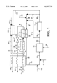
- FIG. 1 is a schematic diagram showing the integration of ion transport oxygen production with oxygen-enriched combustion and a downstream process
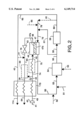
- FIG. 2 is a schematic diagram showing the integration of ion transport oxygen production with oxygen-enriched combustion and a downstream process similar to FIG. 1;
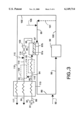
- FIG. 3 is a schematic diagram similar to FIG. 2 where the combustor is integrated with the ion transport module;
- FIG. 4 is a schematic diagram showing how the ion transport process, combustor, and downstream process are integrated in a single module
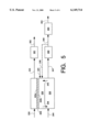
- FIG. 5 is a schematic diagram showing an embodiment of the ion transport process, combustor, and downstream process integrated in a single module
- FIG. 6 is a schematic diagram showing an embodiment of two separate ion transport membrane processes in which no flue gas recirculation is used in one of the processes.
- the present invention discloses process configurations that enable the economically attractive integration of ion transport oxygen production with oxygen-enriched combustion (OEC).
- OEC oxygen-enriched combustion
- pressure-driven processes for ion transport membranes are preferred because of the simplicity of their design, the concepts described herein are applicable to membrane systems utilizing either an ionic-conductor-only membrane having electrodes and an external circuit for electron return or a mixed conductor membrane.
- the essence of the current process configuration is an ion transport membrane that employs a solid oxygen ion conducting or mixed conducting membrane to separate oxygen from an oxygen-containing gas, typically, but not necessarily, air, and to utilize the oxygen separated in a downstream process including, but not limited to, oxygen-enriched combustion.
- an oxygen-depleted gas for example, waste gases from the combustion process or any downstream process
- purging greatly enhances the driving force across the ion transport membrane and effects a high oxygen flux and a lower membrane area requirement.
- Recirculation of the combustion exhaust gas is also beneficial because it provides a diluent stream that is important for controlling the temperature in the combustor and minimizing NO x formation (for example, from nitrogen contained in infiltrating ambient air). Efficiency of this process could also be enhanced by adding fuel to the flue gas entering the oxygen separator. This further reduces the partial pressure oxygen on the permeate side, resulting in even higher oxygen fluxes in the ion transport separator.
- the ion transport module can also function as the combustor, thereby eliminating the need for a separate combustor, unless the application requires a gas stream exiting the combustor at a temperature above 1100° C., the maximum operating temperature of many current ion transport membranes.
- the heat necessary to maintain the temperature of the ion transport module within the operating range can come from a variety of sources known to those skilled in the art, including, for example, heat generated in an afterburner and recirculated hot combustion product gases, among others.
- FIG. 1 is a schematic diagram showing the integration of ion transport oxygen production with oxygen-enriched combustion.
- feed gas stream 1 containing elemental oxygen, usually air is compressed to a relatively low pressure in blower or compressor 2 to produce compressed feed gas stream 3 which is heated in heat exchanger 33 against waste gas stream 31 and product nitrogen gas stream 37 to produce warmed feed gas stream 4.
- Gas stream 28 may be divided from warmed feed gas stream 4 and used in optional afterburner 26 to leave feed gas stream 5 which is optionally heated in heater 34 to produce hot feed gas stream 6.
- Hot feed gas stream 6 then enters the feed side of ion transport module 35 employing ion transport membrane 7 having a retentate side 7a and a permeate side 7b.
- a portion of the oxygen in hot feed gas stream 6 is removed in ion transport module 35 and the exiting gas stream 8 becomes nitrogen-enriched with respect to feed gas stream 1.
- the permeate side 7b of ion transport membrane 7 is purged using purge gas stream 9 containing products of combustion.
- Permeate gas stream 10 contains oxygen and this gas stream 10 is later mixed with fuel gas stream 11. Air, oxygen or oxygen enriched air stream 12 can be optionally added to gas stream 10.
- Combustible gas stream 13 after passing through an optional blower (not shown), then enters combustor 14.
- fuel gas stream 15 can be fed directly to combustor or furnace 14 to generate heat and transfer heat to a furnace charge or to heat transfer surfaces.
- the oxygen concentration in exhaust gas stream 16 can be maintained at low levels.
- exhaust gas stream 16 from combustor 14 is split into two portions, gas stream 17 and gas stream 18.
- Gas stream 18 is used optionally in downstream process 19 that requires heat input and the relatively cooler exhaust gas stream 20 from downstream process 19 may also be split into two portions, exhaust gas stream 21 and exhaust gas stream 22.
- Fuel gas stream 25 may be added to exhaust gas stream 21 to produce gas stream 38.
- Gas stream 38 can be added to gas stream 17 to produce gas stream 9 which enters ion transport module 35 and is used to purge the permeate side 7b of ion transport membrane 7.
- gas stream 17 or combustor 14 can be used to heat feed air 3 and/or warmed feed gas stream 5 by heat exchange to produce hot feed gas stream 6 rather than using heat exchanger 33 and/or optional heater 34.
- Exhaust gas stream 22 optionally fed into an optional afterburner 26 where air stream 27 or gas stream 28 is optionally added to produce hot waste gas stream 29.
- Hot waste gas stream 29 may become gas stream 30 or gas stream 31.
- gas stream 31 is used in heat exchanger 33 to heat compressed feed gas stream 3 to produce waste gas stream 32.
- Gas stream 30 may be mixed with nitrogen-rich retentate gas stream 8 if nitrogen is not to be used as a co-product and if the temperature of exhaust gas stream 30 is adequately high.
- Retentate gas stream 8 is at a higher pressure than exhaust gas stream 30 and it may be necessary to release the excess pressure of retentate gas stream 8 using expansion valve 23 to produce retentate gas stream 36 before it is mixed with gas stream 30.
- the pressure of stream 8 exceeds 2 atm, it is advantageous to replace expansion valve 23 with an expansion turbine to extract shaft work or to generate power. If retentate gas stream 24 is desired as a nitrogen-rich product gas stream, gas streams 36 and 30 are not mixed.
- an oxygen-depleted purge gas stream 9 in ion transport module 35 will greatly lower the oxygen partial pressure on the permeate side 7b of ion transport membrane 7 and enable rapid oxygen transport through membrane 7.
- Fuel gas streams 11, 15, and 25 can be introduced into the process configuration at any or all of the points shown in FIG. 1 to obtain the benefits of the invention; the use of at least one fuel gas stream is essential for the invention. For example, it may be desirable to add fuel gas stream 25 upstream of ion transport module 35 to greatly reduce the oxygen partial pressure on the permeate side 7b of ion transport membrane 7. This would also result in some heat generation in ion transport module 35 due to fuel combustion, thereby offsetting some of the heating requirements of the oxygen transport process.
- the exiting nitrogen-rich gas stream 8 from ion transport module 35 could be made hotter. This would make the heat transfer in heat exchanger 33 more efficient, thereby reducing the area required for the heat exchange and potentially eliminating the need for heater 34 upstream of ion transport module 35. If enough fuel can be combusted in ion transport module 35 on the purge or permeate side 7b of ion transport membrane 7, it may altogether eliminate the need for a separate combustor 14, that is, ion transport module 35 would also serve as the combustor (as described in FIG. 3). In such a situation, significant system simplification and cost reduction may result.
- Reactive purge arrangements are disclosed in "Reactive Purge for Solid Electrolyte Membrane Gas Separation", U.S. Ser. No. 08/567,699, filed Dec. 5, 1995, now U.S. Pat. No. 5,837,125 and incorporated herein by reference.
- Preferred configuration for ion transport modules utilizing a reactive purge are disclosed in "Solid Electrolyte Ionic Conductor Reactor Design", U.S. Ser. No. 08/848,204, filed Apr. 29, 1997, U.S. Pat. No. 5,820,655 and also incorporated herein by reference. Both applications are commonly owned with the present application.
- gas stream 17 is optionally used to purge the permeate side 7b of ion transport membrane 7.
- hydrogen gas is a highly reducing gas with a higher reactivity than many other gaseous fuels, and its presence in ion transport module 35 will result in an extremely low oxygen partial pressure on the purge side 7b of ion transport membrane 7 and this will enable an even more rapid transport of oxygen through ion transport membrane 7.
- afterburner 26 (perhaps catalytic) to which excess air 27 is added to burn off the carbon monoxide and hydrogen gas if their concentration is sufficiently high.
- Gas stream 28 of warmed feed gas stream 4 could also be added to afterburner 26 to provide for the afterburner requirements.
- Typical ranges for operating parameters of the ion transport module used in the invention are as follows.
- Temperature Typically in the 400-1000° C. range, and preferably in the 400-800° C. range.
- the purge side pressure will be typically in 1-3 atm. range.
- the feed side pressure will be 0.8-3 atm. if nitrogen is not a co-product, and 1-20 atm. if nitrogen is a co-product.
- the ion transport membrane can be employed in the form of a dense film, or a thin film supported on a porous substrate.
- the thickness (t) of the ion transport membrane/layer will be typically less than 5000 microns; preferably less than 1000 microns, and most preferably less than 100 microns.
- the ion transport membrane elements may be tubular or planar.
- asymmetric or composite ion transport membranes that is, pressure-driven membranes
- the following properties are based on typical values reported in the literature for such membranes as could be used in the present invention.
- Standard mathematical models have been employed to determine the operating conditions for the process shown in FIG. 1, that is, the membrane area requirement and the power and thermal energy inputs required at various points.
- This example modeling a process using a configuration of FIG. 1, is for illustrative purposes only and no attempt has been made to optimize the process configuration. The major reason why optimization is not attempted is that optimization is generally based on economic considerations and the commercial production of ion transport membrane systems is yet far from being mature, and no reliable cost estimates are presently available on such systems.
- fuel is added only to the process as fuel gas stream 11.
- optional gas stream 17 is not considered, that is, gas streams 16 and 18 are identical.
- nitrogen is not sought as a co-product and retentate gas stream 36, obtained from retentate gas stream 8 after reducing the excess pressure of the retentate using release valve 23, is mixed with gas stream 30, taken from exhaust gas stream 29. In general, however, it is not effective to lower the pressure of retentate gas stream 8 or to add gas stream 30 to retentate gas stream 8 upstream of heat exchanger 33. Since exhaust gas stream 22 does not contain carbon monoxide and hydrogen gas, afterburner 26 is not installed.
- FIG. 2 is a schematic diagram similar to FIG. 1 showing a more efficient alternative using the catalytic afterburner installation.
- feed gas stream 41 containing elemental oxygen usually air
- blower or compressor 42 to produce compressed feed gas stream 43 which is heated in heat exchanger 73 against hot waste gas stream 40 and product nitrogen gas stream 64 to produce warmed feed gas stream 44.
- Gas stream 70 may be divided from warmed feed gas stream 44 and used in optional afterburner 69 to leave feed gas stream 74 which is optionally heated in heater 75 to produce hot feed gas stream 45.
- Hot feed gas stream 45 then enters the feed side of ion transport module 46 employing ion transport membrane 47 having a retentate side 47a and a permeate side 47b. A portion of the oxygen in hot feed gas stream 45 is removed in ion transport module 46 and the exiting gas stream 48 becomes nitrogen-enriched with respect to feed gas stream 41.
- Permeate gas stream 50 contains oxygen and this gas stream 50 is later mixed with fuel gas stream 51.
- Air, oxygen or oxygen enriched air stream 52 can be optionally added to gas stream 50.
- Combustible gas stream 53 after passing through an optional blower (not shown), then enters combustor or furnace 54.
- fuel gas stream 55 can be fed directly to combustor 54.
- heat is transferred to a charge or heat transfer surfaces.
- Exhaust gas stream 56 from combustor 54 may be split into two portions, gas stream 57 and gas stream 58.
- Gas stream 58 is used in downstream process 59 that requires heat input and the relatively cooler exhaust gas stream 60 from downstream process 59 may also be split into two portions, exhaust gas stream 61 and exhaust gas stream 62.
- Fuel gas stream 65 may be added to exhaust gas stream 61 to produce gas stream 78.
- Gas stream 78 can be added to gas stream 57 to produce gas stream 79 which enters ion transport module 46 and is used to purge the permeate side 47b of ion transport membrane 47.
- Exhaust gas stream 62 may optionally be divided into two portions, hot waste gas stream 40 and gas stream 77.
- hot waste gas stream 40 is used in heat exchanger 73 to heat compressed feed gas stream 43 to produce waste gas stream 174.
- Gas stream 77 may be mixed with nitrogen-rich retentate gas stream 48 if nitrogen is not to be used as a co-product and if the temperature of exhaust gas stream 77 is adequately high. The reason for this step is to remove any unreacted fuel in exhaust gas stream 62 by combustion in afterburner 69 and to also generate heat energy to improve the efficiency of heat exchanger 73.
- Retentate gas stream 48 is likely to be at a higher pressure than exhaust gas stream 77 and it may be necessary to release the excess pressure of retentate gas stream 48 using expansion valve 63 to produce retentate gas stream 76 before it is mixed with gas stream 77 to produce gas stream 80.
- Gas stream 80 is fed into optional afterburner 69 where gas stream 70 is optionally added to produce hot waste gas stream 39. In this case one would need to make sure that stream 80 contains enough oxygen for the combustion to proceed to completion.
- gas stream 70 taken from warmed feed gas stream 44 can be optionally added to afterburner 69 to ensure this. It should be noted that the flow rate of the combined stream is increased by blending the exhaust gases from ion transport module 46 and downstream process 59. This improves the capacity ratio in heat exchanger 73 and increases the heat transfer to compressed feed gas stream 43.
- Product gas stream 64 will contain oxygen (used in excess to ensure complete combustion) and products of combustion if afterburner 69 is used and product gas stream 64 is generally discarded as a waste stream.
- an oxygen-depleted purge gas stream 79 in ion transport module 46 will greatly lower the oxygen partial pressure on the permeate side 47b of ion transport membrane 47 and enable rapid oxygen transport through membrane 47.
- Fuel gas streams 51, 55, and 65 can be introduced into the process configuration at any or all of the points shown in FIG. 2 to obtain the benefits of the invention and the use of at least one fuel gas stream is essential for the invention. As before, it may be desirable to add fuel gas stream 65 upstream of ion transport module 46 to greatly reduce the oxygen partial pressure on the permeate side 47b of ion transport membrane 47.
- gas stream 57 is optionally used to purge the permeate side 47b of ion transport membrane 47 and the presence of hydrogen gas in ion transport module 46 will result in an extremely low oxygen partial pressure on the purge side 47b of ion transport membrane 47 and this will enable an even more rapid transport of oxygen through ion transport membrane 47.
- the use of a fuel-rich feed to combustor 54 produces hydrogen gas as a part of the process cycle.
- afterburner 69 perhaps catalytic
- FIG. 3 is a schematic diagram showing another embodiment of the invention where the combustor is integrated with the ion transport module, that is, where the ion transport module itself serves as the combustor.
- feed gas stream 81 containing elemental oxygen, usually air is compressed to a relatively low pressure in blower or compressor 82 to produce compressed feed gas stream 83 which is heated in heat exchanger 113 against hot waste gas stream 116 and product nitrogen gas stream 93 to produce warmed feed gas stream 95.
- Gas stream 110 may be divided from warmed feed gas stream 95 and used in optional afterburner 109 to leave feed gas stream 84 which is optionally heated in heater 114 to produce hot feed gas stream 85.
- Hot feed gas stream 85 then enters the feed side of ion transport-combustor module 86 employing ion transport membrane 87 having a retentate side 87a and a permeate side 87b. A portion of the oxygen in hot feed gas stream 85 is removed in ion transport-combustor module 86 and the exiting gas stream 88 becomes nitrogen-enriched with respect to feed gas stream 81.
- the permeate side 87b of ion transport membrane 87 is purged using purge gas stream 89 containing products of combustion and fuel.
- Permeate gas stream 90 contains oxygen and air stream 92 can be optionally added to gas stream 90 to produce gas stream 98.
- the oxygen concentration in exhaust gas stream 90 can be maintained at low levels.
- Gas stream 98 is used in downstream process 99 that requires heat input and the relatively cooler exhaust gas stream 100 from downstream process 99 is also be split into two portions, exhaust gas stream 101 and exhaust gas stream 102.
- Fuel gas stream 105 preferably is added to exhaust gas stream 101 to produce gas stream 89 which enters ion transport-combustor module 86 and is used to purge the permeate side 87b of ion transport membrane 87.
- Exhaust gas stream 102 may optionally be divided into two portions, hot waste gas stream 116 and gas stream 115.
- hot waste gas stream 116 is used in heat exchanger 113 to heat compressed feed gas stream 83 to produce waste gas stream 117.
- Gas stream 115 may be mixed with nitrogen-rich retentate gas stream 88 if nitrogen is not to be used as a co-product and if the temperature of exhaust gas stream 115 is adequately high. The reason for this step is to remove any unreacted fuel in exhaust gas stream 102 by combustion in afterburner 109 and to also generate heat energy to improve the efficiency of heat exchanger 113.
- Retentate gas stream 88 is likely to be at a higher pressure than exhaust gas stream 115 and it may be necessary to release the excess pressure of retentate gas stream 88 using expansion valve 103 to produce retentate gas stream 118 before it is mixed with gas stream 115 to produce gas stream 119.
- Gas stream 119 is fed into optional afterburner 109 where gas stream 110 is optionally added to produce hot waste gas stream 93. In this case one would need to make sure that stream 119 contains enough oxygen for the combustion to proceed to completion.
- gas stream 110 taken from warmed feed gas stream 95 can be optionally added to afterburner 109 to ensure this. It should be noted that the flow rate of the combined stream is increased by blending the exhaust gases from ion transport-combustor module 86 and downstream process 99. This improves the capacity ratio in heat exchanger 113 and increases the heat transfer to compressed feed gas stream 83.
- Gas stream 94 will contain oxygen (used in excess to ensure complete combustion) and products of combustion if afterburner 109 is used and gas stream 94 is generally discarded as a waste stream.
- ion transport membrane 87 may be formed as tubes with reactive purge gas stream 89 flowing inside the tubes. Owing to the heat generated on the purge side 87b of ion transport membrane 87 formed as tubes, the tubes will be at a high temperature and will act as heating elements. The ion transport membrane 87 tubes will radiate to the retentate side 87a or permeate side 87b where a process such as glass melting or metal annealing could be carried out.
- a part of the heat generated in ion transport module 86 could be used to preheat compressed feed gas stream 85 and purge gas stream 89, possibly obviating the need for heat exchanger 113 and heater 114.
- the furnace load will be placed on the permeate side 87b of ion transport membrane 87 (that is, the side with the oxidizing gas) in this case.
- ion transport-combustor module with an internal circulation of the flue (furnace) gas. If the furnace and the ion transport-combustor module operate at about the same temperature (for example, between 800°-1200° C.), then the ion transport-combustor module can be placed directly inside the furnace provided that the furnace atmosphere is "clean", that is, it does not contain any species detrimental to the ion transport membrane.
- FIG. 4 One way of implementing this idea is shown in FIG. 4 in which the ion transport process, combustor, and downstream process are all integrated in a single unit. Feed stream 132 such as heated air is directed against cathode side 120a of membrane 120 to produce hot, oxygen-depleted retentate 134 such as nitrogen.
- Downstream process 130 (for example, a furnace load) is shown on the permeate or anode side 120b of ion transport membrane 120.
- fuel gas stream 121 is fed close to the surface of permeate side 120b, thus sweeping away and/or efficiently consuming oxygen transported across ion transport membrane 120.
- the combustion products in hot zone 138 could be recirculated in the furnace against anode side 120b by natural or forced convection; for the construction shown in FIG. 4, combustion products stream 146, preferably obtained from furnace 130 as shown in phantom by stream 146a, and the fuel gas stream 121 are optionally fed through porous fuel distributor layer 122 adjacent to permeate side 120b of ion transport membrane 120.
- distributor layer 122 defines at least one passage or chamber to more uniformly distribute fuel across the membrane 120.
- Reacted permeate 136 containing oxygen and combustion products is directed to furnace 130 through hot zone 138.
- a portion of hot nitrogen 140 is directed through valve 142 to provide an inerting atmosphere over the furnace 130.
- Additional fuel 144 may be added to furnace 130 as desired.
- the ion transport membrane 120 is part of a separate module that is external to the furnace 130.
- a two-stage ion transport system can be established in which the anode side of the first stage is purged by the retentate stream from the first stage to produce a diluted oxygen permeate stream while the anode side of the second stage is reactively purged to produce a fuel-rich permeate stream
- the two permeate streams are used in a furnace for combustion with or without use of the hot nitrogen retentate streams in the furnace atmosphere.
- a furnace zone with the "right" temperature may be selected for ion transport operation (for example, preheat section of a continuous reheat furnace), or a special chamber with proper heat sinks to control the temperature can be created.
- the furnace heat loads that is, water or oil tubes
- a large amount of flue gas is circulated through this zone to continuously purge oxygen and keep the oxygen concentration low.
- Low oxygen concentration and high furnace gas circulation provide a synergy with the dilute oxygen combustion method.
- the oxygen for the OEC can be extracted from a low pressure feed gas stream by using the exhaust gas stream for purging and this should result in low power requirement for the oxygen separation process.
- the separate combustor unit can be eliminated. This would yield significant system simplification and cost savings.
- the nitrogen-rich stream retentate from the ion transport module can be used as a product. This may be most attractive if some fuel is added, for example, fuel gas stream 11. If nitrogen is desired as a co-product, it may be advantageous to compress the feed gas stream to the pressure required for product nitrogen supply.
- the retentate gas stream from the ion transport module may not be mixed with the exhaust gas stream from the downstream process. In this case, either a separate heat exchanger can be installed to recover heat from the exhaust gas stream, or no heat recovery may be attempted since generally exhaust gas stream will be much smaller and colder as compared to the retentate gas stream.
- the use of the purge gas stream decreases the oxygen concentration on the permeate side of the ion transport membrane.
- the reduced oxygen concentration makes the design of the ion transport module and of the downstream components (for example, combustor) on the purge side considerably easier from a materials standpoint.
- essentially pure oxygen would be produced on the permeate side of the ion transport membrane. Safe handling of such a high purity oxygen stream poses a significant challenge, especially at elevated temperature.
- the concentration of the oxygen in the purge exhaust can be easily controlled by a number of techniques: for example, varying the feed gas stream flowrate, varying the purge gas stream flowrate (increased recycle of the combustion products), changing the ion transport module operating temperature, or varying the membrane area of the ion transport stage. These techniques are also effective in controlling the total amount of oxygen separated and could be used for load tracking purposes.
- the use of the ion transport separator would eliminate the need for a stand-alone oxygen generator (for example, PSA) or an oxygen supply system (for example, liquid tank and vaporizer). This is expected to yield substantial reduction in capital cost and in the cost of the oxygen produced.
- a stand-alone oxygen generator for example, PSA
- an oxygen supply system for example, liquid tank and vaporizer
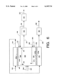
- FIG. 5 An embodiment particularly directed to this invention is shown in FIG. 5.
- the feed stream or air 232 is preheated to a suitable temperature of about 500° C. to 1000° C.
- the feed stream or air preferably contains a relatively high oxygen concentration of typically greater than 15% oxygen.
- the feed stream or air 232 is then introduced to the retentate side 220a of ion transport membrane 220 through permeate side 220b to the permeate chamber 238, which is connected to the main combustion chamber or furnace 230.
- the temperature of the main chamber is determined by the requirement of the heating process and can be higher or lower than the temperature of the permeate chamber 238.
- a significant portion of flue gas generated in furnace 230 is recirculated as stream 246, to permeate chamber 238.
- Stream 246 causes the oxygen concentration in the permeate side 220b of the ion transport membrane 220 to be low and increases oxygen flux through oxygen transport membrane 220.
- fuel stream 221 can be introduced to permeate chamber 238 to reduce the oxygen concentration of recirculated stream 246 and/or to reactively purge the permeate side 220b and also to provide heat to raise the air temperature on the retentate side.
- Permeate chamber 238 is optionally segmented into a two stage ion transport membrane system using a reactive purge in the first stage and a flue gas purge in the second stage (not shown).
- Fuel stream 221 is preferably injected at high velocity to induce proper circulation of hot flue gas stream 246 from furnace 230 by the aspiration effect of high velocity jets.
- Other means of hot flue gas recirculation including, but not limited to, a circulation fan and an eductor using compressed flue gas or steam can be used.
- external recirculation stream 248 may be used.
- flue gas stream 247 from furnace 230 is cooled in heat exchanger 260 and cooled side stream 248 is compressed and injected into first chamber 238 to induce proper circulation of the hot flue gas stream 246.
- the process can be used for many industrial furnaces such as metal heat treating, steel reheating, glass melting and aluminum melting furnaces, but it is particularly suitable for boilers to generate steam and for process fluid heating furnaces such as petroleum heaters, cracking furnaces and steam-methane reformer furnaces.
- process fluid heating furnaces such as petroleum heaters, cracking furnaces and steam-methane reformer furnaces.
- the purge gas preferably contains a low concentration of nitrogen, which through transport to the permeate side of the ion transport membrane forms oxidant stream 236 containing between 1% to 40% oxygen, preferably between 2% to 15% oxygen, and most preferably between 3% to 10% oxygen.
- the ion transport membrane 220 effectively forms two sides of the reactive area having a same or different pressure, the retentate side 220a having a first pressure and a permeate side 220b having a second pressure.
- the ratio of the first pressure to the second pressure is less than 4.78, preferably between 0.5 to 4.0, more preferably between 0.8 to 2.0, and most preferably between 0.9 to 1.5.
- feed air has to be compressed to a minimum pressure at 4.78 atm in order to achieve an oxygen partial pressure of 1 atm in the retentate side.
- a theoretical minimum pressure ratio of 4.78 is required to produce pure oxygen at 1 atm in the permeate side.
- this invention allows permeation of oxygen through the ion transport membrane even when the pressure ratio is less than 1, i.e., the pressure of the retentate side is lower than that of the permeate side. It is because the permeation of oxygen is driven by the ratio of the oxygen partial pressure of the retentate side to that of the permeate side. By keeping the oxygen partial pressure low in the permeate side, it is possible to achieve an oxygen partial pressure ratio of greater than 2 while maintaining the total pressure ratio near or below 1.
- fuel jets are optionally used to recirculate hot flue gas from the furnace 230 into the permeate chamber 238.
- Steam jets or other gas jets such as compressed cooled flue gas stream 248, can be used to provide additional purge gas and to facilitate the circulation of flue gas through the jet pump effect.
- the fuel jet reacts with the oxygen contained in the recirculated flue gas and oxygen permeated from the ion transport membrane tubes, reducing the oxygen concentration in permeate chamber 238 and generating heat.
- Boiler tubes, steam super heater tubes and/or steam reheat tubes may be optionally placed in the permeate chamber 238 as heat sinks to control the chamber temperature.
- the temperature of the membrane tube in the permeate chamber 238 is preferably maintained at an optimum membrane temperature, typically between 600° C. and 1000° C., by controlling the flow rate of feed air 232, the flow rate of fuel 221 injected into this permeate chamber 238 and the amount of recirculated hot flue gas 246.
- the average oxygen concentration in the oxidant mixture 236, which consists of combustion products of fuel 221, oxygen transported through the ion transport membrane 220, and recirculated flue gas 246, at the exit of the permeate chamber 238 may be controlled from 1% to 40% oxygen, preferably 2% to 10%, and most preferably between 3 to 10% oxygen. This mixture is circulated to the combustion chamber 230, preferably without cooling.
- the air flow through the retentate side of the ion transport membrane tubes and the fuel/flue gas flow in the permeate side can be arranged in a counter current fashion to maximize the oxygen flux through the ion transport membrane tubes.
- Lower oxygen concentration in the permeate side 220b is generally preferred to increase the oxygen permeation rate of the ion transport membrane.
- a large volume of flue gas has to be recirculated to keep the oxygen concentration low. Thus, the above mentioned range is preferred.
- furnace 230 fuel 244 is injected and mixed with the hot dilute oxygen stream 236 from permeate chamber 238 for combustion to generate steam in the conventional fashion for the radiant section of a steam boiler.
- the dilute oxygen combustion process as described in H. M. Ryan, et al., Development of the Dilute Oxygen Combustion Burner for High Temperature Furnace Applications, Proceedings of the Fourth International Conference on Technologies and Combustion or Clean Environment, Jul. 7-10, 1997 and U.S. Pat. No. 5,076,779 disclose the preferred combustion process to achieve low NO x emissions and high thermal efficiency.
- Flue gas stream 249 is optionally passed through a condensing heat exchanger 264 to recover the latent heat of water vapor in the flue gas.
- the full recovery of the latent heat of water vapor in flue gas provides a theoretical energy improvement of about 10% for natural gas combustion, in addition to the efficiency improvement as a result of reduced sensible heat in cooled flue gas stream 263.
- Oxygen combustion provides a unique advantage over air combustion for the recovery of latent heat due to the high concentration of water vapor in flue gas.
- the concentration of water vapor in the flue gas from natural gas-oxygen combustion is about 65% and the dew point is about 88° C.
- the concentration of water vapor is reduced to 13% by volume.
- about 93% of water vapor can be condensed.
- the concentration of water vapor in the flue gas from natural gas-air combustion is about 18% and the dew point is about 58° C.
- the flue gas is about 49° C., about 41% of water vapor can be condensed. Further cooling to 32° C. is required to condense about 77% of water vapor in natural gas-air combustion.
- an unexpectedly large fraction of water vapor contained in flue gas can be condensed at relatively high temperature when natural gas or a fuel with a high hydrogen to carbon atomic ratio is combusted with oxygen.
- By condensing water vapor the flue gas volume is further reduced and the carbon dioxide rich stream is produced for potential recovery and production of carbon dioxide.
- Hot nitrogen-rich stream 234 from retentate chamber is passed through a convective heat transfer unit 261 to heat feed water and optionally provide heat for steam generation, super heating or reheating. Alternatively this hot stream 234 can be used to preheat feed air, as shown in FIGS. 1 to 3.
- a high purity nitrogen stream can be produced using a two stage ion transport membrane system with a reactive purge in the first stage and a flue gas purge in the second stage.
- Heating of feed air stream 232 can also be done indirectly in a heat exchanger (not shown) with hot flue gas stream 247 and/or by placing air heating tubes in furnace 230 and/or in permeate chamber 238.
- an in-line combustor (not shown) can be used to heat air to a higher temperature.
- Tables IV and V show an example of specifications of an integrated ion transport membrane-combustion process depicted in FIG. 5.
- a large amount of hot flue gas is recirculated to keep the oxygen concentration in the permeate side of the membrane at 7.43%, which helps to increase the oxygen flux through the membrane without compressing air feed stream to a high pressure.
- substantially all of oxygen contained in feed air stream 232 permeates through ion transport membrane 220 and used for combustion with fuel streams 221 and 244.
- the flow rate of air feed is 44,290 SCFH as compared 165,400 SCFH in the previous example shown in Table II.
- the large reduction in the air feed rate reduces the amount of heat required to heat feed air and the power required in feed air blower.
- the blower power required in this example is 9.3 kw and 11,740 SCFH of oxygen is separated by the ion transport membrane, corresponding to 0.079 kw of power per 100 SCFH of oxygen.
- the previous example consumes 58 kw of power to produce 11,600 SCFH of oxygen, corresponding to 0.5 kw of power per 100 SCFH.
- the current state-of-the-art air separation technologies consume about 0.8 kw of power to produce 100 SCFH industrial grade oxygen at 90% to 95% oxygen purity and at 1 atmosphere.
- the integrated ion transport membrane-combustion processes of this invention reduce the power consumption to separate air for oxygen combustion by as much as 90%.
- FIG. 5 embodiment 232 and 332 provides for a process where no flue gas recirculation is used in a reactively purged ion transport membrane chamber of a two-membrane chamber combustion process depicted in FIG. 6.
- Certain common features in both FIGS. 5 and 6 are not repeated herein, and the common features may be referred to in the description of the FIG. 5 embodiment 232 and 332; 220 and 320; 220a and 320a; 220b and 320b; 221 and 321; 248 and 348; 246 and 346; 247 and 347; 249 and 349; 263 and 363; and 264 and 364.
- hot nitrogen-rich stream 334 from the first rententate chamber is introduced into the second retentate side 372a of the ion transport membrane 372 in the second retentate chamber 370.
- Oxygen permeates through the second permeate side 372b of the ion transport membrane 372 into the second permeate chamber 350, in which reactively purged high oxygen flux is achieved even when nitrogen feed stream 334 contains low concentration of oxygen.
- Fuel stream 355 is injected into the second permeate chamber 350 to react with the oxygen flux from the second permeate side 372b of the ion transport membrane 372, thereby forming hot syngas stream 373, a gas stream containing combustible gases such as hydrogen and carbon monoxide.
- recycled flue gas or steam 356 may is injected into the second permeate chamber 350 to modulate the temperature.
- Hot syngas stream 373 is introduced into furnace 330 and mixed with hot oxidant stream 336 from the first permeate chamber 338, which provides the oxygen for combustion.
- additional air or oxygen stream 357 is injected into furnace 330 to combust the hot syngas stream 373 and to provide heat to the process.
- Nitrogen-rich stream 334 is enriched as it passes across the second retentate side 372a, where oxygen is removed as it passes through second ion transport membrane 372 into second permeate chamber 350, and a stream of high purity nitrogen 365 is formed. High purity nitrogen stream 365 then passes through convective heat transfer unit 361 to recover cool nitrogen stream 362 for use or further processing.
- solid electrolyte ionic conductor solid electrolyte
- ionic conductor ionic conductor
- ion transport membrane ion transport membrane
- nitrogen will usually mean oxygen-depleted gas, that is, oxygen-depleted relative to the feed gas.
- oxygen-depleted gas that is, oxygen-depleted relative to the feed gas.
- the ion transport membrane only allows oxygen permeation. Therefore, the composition of the retentate will depend on the composition of the feed gas.
- the feed gas will be depleted of oxygen but will retain nitrogen and any other gases (for example, argon) present in the feed gas.
- any other gases for example, argon
- elemental oxygen means any oxygen that is uncombined with any other element in the Periodic Table. While typically in diatomic form, elemental oxygen includes single oxygen atoms, triatomic ozone, and other forms uncombined with other elements.
- high purity refers to a product stream which contains less than five percent by volume of undesired gases.
- the product is at least 98.0% pure, more preferably 99.9% pure, and most preferably at least 99.99% pure, where "pure" indicates an absence of undesired gases.
- PSA Pressure-swing adsorption
- adsorption materials which are selective for a gas, typically nitrogen, to separate that gas from other gases.
- Such materials include rate-selective PSA materials, which are usually carbon-containing and provide high pressure nitrogen and low pressure oxygen, and equilibrium-selective PSA materials, which are usually lithium-containing and provide low pressure nitrogen and high pressure oxygen.
Landscapes
- Chemical & Material Sciences (AREA)
- Engineering & Computer Science (AREA)
- Analytical Chemistry (AREA)
- General Chemical & Material Sciences (AREA)
- Oil, Petroleum & Natural Gas (AREA)
- Chemical Kinetics & Catalysis (AREA)
- Organic Chemistry (AREA)
- Combustion & Propulsion (AREA)
- General Engineering & Computer Science (AREA)
- Inorganic Chemistry (AREA)
- Mechanical Engineering (AREA)
- Electrochemistry (AREA)
- Separation Using Semi-Permeable Membranes (AREA)
Priority Applications (9)
| Application Number | Priority Date | Filing Date | Title |
|---|---|---|---|
| US09/280,340 US6149714A (en) | 1997-06-05 | 1999-03-29 | Process for enriched combustion using solid electrolyte ionic conductor systems |
| CA002302143A CA2302143A1 (fr) | 1999-03-29 | 2000-03-27 | Procede de combustion enrichie utilisant des systemes de conducteurs ioniques a electrolytes solides |
| CN00104819A CN1269488A (zh) | 1999-03-29 | 2000-03-27 | 用固体电解质离子导体体系增强燃烧的方法 |
| ZA200001543A ZA200001543B (en) | 1999-03-29 | 2000-03-27 | Process for enriched combustion using solid electrolyte ionic conductor systems. |
| AU22592/00A AU2259200A (en) | 1999-03-29 | 2000-03-27 | Process for enriched combustion using solid electrolyte ionic conductor systems |
| JP2000085961A JP2000304206A (ja) | 1999-03-29 | 2000-03-27 | 固体電解質イオン導体システムを使用する富化燃焼方法 |
| BR0001491-5A BR0001491A (pt) | 1999-03-29 | 2000-03-27 | Processo de combustão usando um oxidante com uma baixa concentração de nitrogênio |
| KR1020000015532A KR20010029606A (ko) | 1999-03-29 | 2000-03-27 | 고체 전해질 이온 전도체 시스템을 이용한 보강된 연소 공정 |
| EP00106563A EP1040861A1 (fr) | 1999-03-29 | 2000-03-27 | Procédé pour la combustion enrichie utilisant des systèmes avec une membrane solide électrolitique |
Applications Claiming Priority (2)
| Application Number | Priority Date | Filing Date | Title |
|---|---|---|---|
| US08/868,962 US5888272A (en) | 1997-06-05 | 1997-06-05 | Process for enriched combustion using solid electrolyte ionic conductor systems |
| US09/280,340 US6149714A (en) | 1997-06-05 | 1999-03-29 | Process for enriched combustion using solid electrolyte ionic conductor systems |
Related Parent Applications (1)
| Application Number | Title | Priority Date | Filing Date |
|---|---|---|---|
| US08/868,962 Continuation-In-Part US5888272A (en) | 1997-06-05 | 1997-06-05 | Process for enriched combustion using solid electrolyte ionic conductor systems |
Publications (1)
| Publication Number | Publication Date |
|---|---|
| US6149714A true US6149714A (en) | 2000-11-21 |
Family
ID=23072670
Family Applications (1)
| Application Number | Title | Priority Date | Filing Date |
|---|---|---|---|
| US09/280,340 Expired - Lifetime US6149714A (en) | 1997-06-05 | 1999-03-29 | Process for enriched combustion using solid electrolyte ionic conductor systems |
Country Status (9)
| Country | Link |
|---|---|
| US (1) | US6149714A (fr) |
| EP (1) | EP1040861A1 (fr) |
| JP (1) | JP2000304206A (fr) |
| KR (1) | KR20010029606A (fr) |
| CN (1) | CN1269488A (fr) |
| AU (1) | AU2259200A (fr) |
| BR (1) | BR0001491A (fr) |
| CA (1) | CA2302143A1 (fr) |
| ZA (1) | ZA200001543B (fr) |
Cited By (26)
| Publication number | Priority date | Publication date | Assignee | Title |
|---|---|---|---|---|
| US6406518B1 (en) * | 2000-08-21 | 2002-06-18 | Praxair Technology, Inc. | Gas separation process using ceramic membrane and regenerators |
| US6503296B1 (en) * | 1998-05-20 | 2003-01-07 | Norsk Hydro Asa | Membrane and use thereof |
| US6562105B2 (en) * | 2001-09-27 | 2003-05-13 | Praxair Technology, Inc. | Combined method of separating oxygen and generating power |
| US6562104B2 (en) * | 2000-12-19 | 2003-05-13 | Praxair Technology, Inc. | Method and system for combusting a fuel |
| US6702570B2 (en) | 2002-06-28 | 2004-03-09 | Praxair Technology Inc. | Firing method for a heat consuming device utilizing oxy-fuel combustion |
| US6786952B1 (en) * | 1999-09-28 | 2004-09-07 | Norsk Hydro Asa | Membrane and use thereof |
| US20040175663A1 (en) * | 2003-03-06 | 2004-09-09 | M. Shannon Melton | Method for combusting fuel in a fired heater |
| US20070134604A1 (en) * | 2005-12-09 | 2007-06-14 | John Sirman | Fluid heating method |
| US7329306B1 (en) * | 2004-12-02 | 2008-02-12 | Uop Llc | Process for safe membrane operation |
| US20080286707A1 (en) * | 2007-05-15 | 2008-11-20 | Panesar Raghbir S | Combustion apparatus |
| US20090272266A1 (en) * | 2005-02-11 | 2009-11-05 | Uhde Gmbh | Method for oxygenating gases, systems suited therefor and use thereof |
| US20100150773A1 (en) * | 2008-12-11 | 2010-06-17 | Fox Timothy J | Membrane-based compressed air breathing system |
| US20110132280A1 (en) * | 2010-02-18 | 2011-06-09 | Mohamed Abdel-Aziz Habib | Carbo-free fire tube boiler |
| US20110131946A1 (en) * | 2010-04-19 | 2011-06-09 | Mohamed Abdel-Aziz Habib | Carbon-free gas turbine |
| CN103134320A (zh) * | 2011-12-02 | 2013-06-05 | 中国科学院金属研究所 | 低碳节能燃气熔化铝炉 |
| US20130341839A1 (en) * | 2012-06-21 | 2013-12-26 | L'air Liquide Societe Anonyme Pour L'etude Et L'exploitation Des Procedes Georges Claude | Use of oxygen from ion transport membranes in blast furnace |
| JP2014500136A (ja) * | 2010-10-22 | 2014-01-09 | コーニンクレッカ フィリップス エヌ ヴェ | 酸素分離装置及び方法 |
| JP2014513027A (ja) * | 2011-03-03 | 2014-05-29 | コーニンクレッカ フィリップス エヌ ヴェ | 酸素を生成する方法及び構成 |
| US9157890B2 (en) * | 2012-09-04 | 2015-10-13 | Atonarp Inc. | Exchange membrane unit and system including exchange membrane unit |
| US9272937B2 (en) | 2009-08-06 | 2016-03-01 | Agc Glass Europe | Glass melting furnace |
| US20180140996A1 (en) * | 2015-12-15 | 2018-05-24 | United Technologies Corporation | Solid oxide electrochemical gas separator inerting system |
| WO2018198015A1 (fr) * | 2017-04-25 | 2018-11-01 | Nova Chemicals (International) S.A. | Complexe comprenant une unité odh équipé d'un module de séparation d'oxygène intégré |
| US10180253B2 (en) | 2012-10-31 | 2019-01-15 | Korea Institute Of Machinery & Materials | Integrated carbon dioxide conversion system for connecting oxyfuel combustion and catalytic conversion process |
| WO2022136970A1 (fr) * | 2020-12-21 | 2022-06-30 | Sabic Global Technologies B.V. | Procédés de fonctionnement d'un dispositif de chauffage |
| US11466618B2 (en) | 2018-10-25 | 2022-10-11 | Korea Institute Of Energy Research | Direct-fired supercritical carbon dioxide power generation system and method |
| US12618558B2 (en) | 2021-11-18 | 2026-05-05 | Sabic Global Technologies B.V. | Methods for operating a heating device |
Families Citing this family (13)
| Publication number | Priority date | Publication date | Assignee | Title |
|---|---|---|---|---|
| US6537514B1 (en) * | 1999-10-26 | 2003-03-25 | Praxair Technology, Inc. | Method and apparatus for producing carbon dioxide |
| NO318619B1 (no) * | 2000-12-29 | 2005-04-18 | Norsk Hydro As | Anordning for forbrenning av et karbonholdig brensel, en fremgangsmate for a betjene nevnte anordning, samt anvendelse av anordningen. |
| NO314925B1 (no) * | 2001-01-23 | 2003-06-16 | Aker Technology As | Fremgangsmåte for kjöling og oksygenanriking av et arbeidsmedium i en kraftproduserende prosess |
| GB2397540B (en) * | 2002-11-29 | 2005-01-19 | Bosch Gmbh Robert | Process and device for preparation of a fuel |
| US7425231B2 (en) * | 2003-08-06 | 2008-09-16 | Air Products And Chemicals, Inc. | Feed gas contaminant removal in ion transport membrane systems |
| US7954458B2 (en) | 2007-11-14 | 2011-06-07 | Alstom Technology Ltd | Boiler having an integrated oxygen producing device |
| CN101450859B (zh) * | 2007-11-30 | 2011-08-17 | 北京有色金属研究总院 | 用BaCeO3掺杂提高YBaCuO超导体性能的方法 |
| DE102008010928A1 (de) * | 2008-02-25 | 2009-08-27 | Forschungszentrum Jülich GmbH | Feuerungsanlage und Verfahren zum Betreiben einer solchen |
| US9004909B2 (en) | 2012-02-03 | 2015-04-14 | Massachusetts Institute Of Technology | Integrated polymeric-ceramic membrane based oxy-fuel combustor |
| KR101467034B1 (ko) * | 2012-07-19 | 2014-12-02 | 한국기계연구원 | 이온 전도성 멤브레인과 이젝터를 이용한 고효율 순산소 연소 시스템 |
| JP2015224148A (ja) * | 2014-05-27 | 2015-12-14 | 日本特殊陶業株式会社 | 酸素富化燃焼システムおよび酸素富化燃焼方法 |
| CN107359110A (zh) * | 2017-08-03 | 2017-11-17 | 四川科尔威光电科技有限公司 | 一种用于氮化铝陶瓷基片氧化处理方法 |
| US20190211782A1 (en) * | 2018-01-10 | 2019-07-11 | Reliable Energy Group Corp. | Internal combustion engine and system |
Citations (19)
| Publication number | Priority date | Publication date | Assignee | Title |
|---|---|---|---|---|
| US4545787A (en) * | 1984-07-30 | 1985-10-08 | Air Products And Chemicals, Inc. | Process for producing by-product oxygen from turbine power generation |
| US5051113A (en) * | 1990-06-13 | 1991-09-24 | Du Pont Canada Inc. | Air-intake system for mobile engines |
| US5053059A (en) * | 1990-06-13 | 1991-10-01 | Du Pont Canada Inc. | Air-intake system for residential furnaces |
| US5118395A (en) * | 1990-05-24 | 1992-06-02 | Air Products And Chemicals, Inc. | Oxygen recovery from turbine exhaust using solid electrolyte membrane |
| US5160713A (en) * | 1990-10-09 | 1992-11-03 | The Standard Oil Company | Process for separating oxygen from an oxygen-containing gas by using a bi-containing mixed metal oxide membrane |
| US5169415A (en) * | 1990-08-31 | 1992-12-08 | Sundstrand Corporation | Method of generating oxygen from an air stream |
| US5174866A (en) * | 1990-05-24 | 1992-12-29 | Air Products And Chemicals, Inc. | Oxygen recovery from turbine exhaust using solid electrolyte membrane |
| US5306411A (en) * | 1989-05-25 | 1994-04-26 | The Standard Oil Company | Solid multi-component membranes, electrochemical reactor components, electrochemical reactors and use of membranes, reactor components, and reactor for oxidation reactions |
| US5354547A (en) * | 1989-11-14 | 1994-10-11 | Air Products And Chemicals, Inc. | Hydrogen recovery by adsorbent membranes |
| US5435836A (en) * | 1993-12-23 | 1995-07-25 | Air Products And Chemicals, Inc. | Hydrogen recovery by adsorbent membranes |
| US5447555A (en) * | 1994-01-12 | 1995-09-05 | Air Products And Chemicals, Inc. | Oxygen production by staged mixed conductor membranes |
| US5516359A (en) * | 1993-12-17 | 1996-05-14 | Air Products And Chemicals, Inc. | Integrated high temperature method for oxygen production |
| US5547494A (en) * | 1995-03-22 | 1996-08-20 | Praxair Technology, Inc. | Staged electrolyte membrane |
| US5562754A (en) * | 1995-06-07 | 1996-10-08 | Air Products And Chemicals, Inc. | Production of oxygen by ion transport membranes with steam utilization |
| EP0747108A2 (fr) * | 1995-06-07 | 1996-12-11 | Air Products And Chemicals, Inc. | Production d'oxygène avec des membanes de transport d'ions et récupération d'énergie |
| EP0778069A1 (fr) * | 1995-12-05 | 1997-06-11 | Praxair Technology, Inc. | Purge réactive pour la séparation de gaz à membranes électrolytiques solides |
| US5643354A (en) * | 1995-04-06 | 1997-07-01 | Air Products And Chemicals, Inc. | High temperature oxygen production for ironmaking processes |
| US5733435A (en) * | 1995-05-18 | 1998-03-31 | Praxair Technology, Inc. | Pressure driven solid electrolyte membrane gas separation method |
| US5888272A (en) * | 1997-06-05 | 1999-03-30 | Praxair Technology, Inc. | Process for enriched combustion using solid electrolyte ionic conductor systems |
-
1999
- 1999-03-29 US US09/280,340 patent/US6149714A/en not_active Expired - Lifetime
-
2000
- 2000-03-27 CN CN00104819A patent/CN1269488A/zh active Pending
- 2000-03-27 AU AU22592/00A patent/AU2259200A/en not_active Abandoned
- 2000-03-27 KR KR1020000015532A patent/KR20010029606A/ko not_active Ceased
- 2000-03-27 EP EP00106563A patent/EP1040861A1/fr not_active Withdrawn
- 2000-03-27 JP JP2000085961A patent/JP2000304206A/ja not_active Abandoned
- 2000-03-27 CA CA002302143A patent/CA2302143A1/fr not_active Abandoned
- 2000-03-27 BR BR0001491-5A patent/BR0001491A/pt not_active Application Discontinuation
- 2000-03-27 ZA ZA200001543A patent/ZA200001543B/xx unknown
Patent Citations (20)
| Publication number | Priority date | Publication date | Assignee | Title |
|---|---|---|---|---|
| US4545787A (en) * | 1984-07-30 | 1985-10-08 | Air Products And Chemicals, Inc. | Process for producing by-product oxygen from turbine power generation |
| US5306411A (en) * | 1989-05-25 | 1994-04-26 | The Standard Oil Company | Solid multi-component membranes, electrochemical reactor components, electrochemical reactors and use of membranes, reactor components, and reactor for oxidation reactions |
| US5354547A (en) * | 1989-11-14 | 1994-10-11 | Air Products And Chemicals, Inc. | Hydrogen recovery by adsorbent membranes |
| US5118395A (en) * | 1990-05-24 | 1992-06-02 | Air Products And Chemicals, Inc. | Oxygen recovery from turbine exhaust using solid electrolyte membrane |
| US5174866A (en) * | 1990-05-24 | 1992-12-29 | Air Products And Chemicals, Inc. | Oxygen recovery from turbine exhaust using solid electrolyte membrane |
| US5051113A (en) * | 1990-06-13 | 1991-09-24 | Du Pont Canada Inc. | Air-intake system for mobile engines |
| US5053059A (en) * | 1990-06-13 | 1991-10-01 | Du Pont Canada Inc. | Air-intake system for residential furnaces |
| US5169415A (en) * | 1990-08-31 | 1992-12-08 | Sundstrand Corporation | Method of generating oxygen from an air stream |
| US5160713A (en) * | 1990-10-09 | 1992-11-03 | The Standard Oil Company | Process for separating oxygen from an oxygen-containing gas by using a bi-containing mixed metal oxide membrane |
| US5516359A (en) * | 1993-12-17 | 1996-05-14 | Air Products And Chemicals, Inc. | Integrated high temperature method for oxygen production |
| US5435836A (en) * | 1993-12-23 | 1995-07-25 | Air Products And Chemicals, Inc. | Hydrogen recovery by adsorbent membranes |
| US5447555A (en) * | 1994-01-12 | 1995-09-05 | Air Products And Chemicals, Inc. | Oxygen production by staged mixed conductor membranes |
| US5547494A (en) * | 1995-03-22 | 1996-08-20 | Praxair Technology, Inc. | Staged electrolyte membrane |
| US5643354A (en) * | 1995-04-06 | 1997-07-01 | Air Products And Chemicals, Inc. | High temperature oxygen production for ironmaking processes |
| US5733435A (en) * | 1995-05-18 | 1998-03-31 | Praxair Technology, Inc. | Pressure driven solid electrolyte membrane gas separation method |
| US5562754A (en) * | 1995-06-07 | 1996-10-08 | Air Products And Chemicals, Inc. | Production of oxygen by ion transport membranes with steam utilization |
| EP0747108A2 (fr) * | 1995-06-07 | 1996-12-11 | Air Products And Chemicals, Inc. | Production d'oxygène avec des membanes de transport d'ions et récupération d'énergie |
| US5753007A (en) * | 1995-06-07 | 1998-05-19 | Air Products And Chemicals, Inc. | Oxygen production by ion transport membranes with non-permeate work recovery |
| EP0778069A1 (fr) * | 1995-12-05 | 1997-06-11 | Praxair Technology, Inc. | Purge réactive pour la séparation de gaz à membranes électrolytiques solides |
| US5888272A (en) * | 1997-06-05 | 1999-03-30 | Praxair Technology, Inc. | Process for enriched combustion using solid electrolyte ionic conductor systems |
Non-Patent Citations (4)
| Title |
|---|
| Kobayashi et al. "Technical and Economic Evaluation of Oxygen Enriched Combustion Systems for Industrial Furnace Applications", Industrial Combustion Technology Symposium, 1986. |
| Kobayashi et al. Technical and Economic Evaluation of Oxygen Enriched Combustion Systems for Industrial Furnace Applications , Industrial Combustion Technology Symposium, 1986. * |
| Kobayashi, "Oxygen Enriched Combustion system Performance Study", U.S. Department of Energy, 1988. |
| Kobayashi, Oxygen Enriched Combustion system Performance Study , U.S. Department of Energy, 1988. * |
Cited By (35)
| Publication number | Priority date | Publication date | Assignee | Title |
|---|---|---|---|---|
| US6503296B1 (en) * | 1998-05-20 | 2003-01-07 | Norsk Hydro Asa | Membrane and use thereof |
| US6786952B1 (en) * | 1999-09-28 | 2004-09-07 | Norsk Hydro Asa | Membrane and use thereof |
| US6406518B1 (en) * | 2000-08-21 | 2002-06-18 | Praxair Technology, Inc. | Gas separation process using ceramic membrane and regenerators |
| US6562104B2 (en) * | 2000-12-19 | 2003-05-13 | Praxair Technology, Inc. | Method and system for combusting a fuel |
| US6562105B2 (en) * | 2001-09-27 | 2003-05-13 | Praxair Technology, Inc. | Combined method of separating oxygen and generating power |
| DE10328863B4 (de) * | 2002-06-28 | 2009-06-25 | Praxair Technology, Inc., Danbury | Befeuerungsverfahren für eine Wärme verbrauchende Vorrichtung unter Verwendung einer Sauerstoff-Brennstoff-Verbrennung |
| US6702570B2 (en) | 2002-06-28 | 2004-03-09 | Praxair Technology Inc. | Firing method for a heat consuming device utilizing oxy-fuel combustion |
| US20040175663A1 (en) * | 2003-03-06 | 2004-09-09 | M. Shannon Melton | Method for combusting fuel in a fired heater |
| US7329306B1 (en) * | 2004-12-02 | 2008-02-12 | Uop Llc | Process for safe membrane operation |
| US20090272266A1 (en) * | 2005-02-11 | 2009-11-05 | Uhde Gmbh | Method for oxygenating gases, systems suited therefor and use thereof |
| US7384452B2 (en) | 2005-12-09 | 2008-06-10 | Praxair Technology, Inc. | Fluid heating method |
| US20070134604A1 (en) * | 2005-12-09 | 2007-06-14 | John Sirman | Fluid heating method |
| US20080286707A1 (en) * | 2007-05-15 | 2008-11-20 | Panesar Raghbir S | Combustion apparatus |
| US9651253B2 (en) * | 2007-05-15 | 2017-05-16 | Doosan Power Systems Americas, Llc | Combustion apparatus |
| US7972415B2 (en) | 2008-12-11 | 2011-07-05 | Spx Corporation | Membrane-based compressed air breathing system |
| US20100150773A1 (en) * | 2008-12-11 | 2010-06-17 | Fox Timothy J | Membrane-based compressed air breathing system |
| US9272937B2 (en) | 2009-08-06 | 2016-03-01 | Agc Glass Europe | Glass melting furnace |
| US20110132280A1 (en) * | 2010-02-18 | 2011-06-09 | Mohamed Abdel-Aziz Habib | Carbo-free fire tube boiler |
| US8590490B2 (en) | 2010-02-18 | 2013-11-26 | King Fahd Univ. Of Petroleum & Minerals | Carbon-free fire tube boiler |
| US8117822B2 (en) | 2010-04-19 | 2012-02-21 | King Fahd University Of Petroleum & Minerals | Carbon-free gas turbine |
| US20110131946A1 (en) * | 2010-04-19 | 2011-06-09 | Mohamed Abdel-Aziz Habib | Carbon-free gas turbine |
| JP2014500136A (ja) * | 2010-10-22 | 2014-01-09 | コーニンクレッカ フィリップス エヌ ヴェ | 酸素分離装置及び方法 |
| JP2014513027A (ja) * | 2011-03-03 | 2014-05-29 | コーニンクレッカ フィリップス エヌ ヴェ | 酸素を生成する方法及び構成 |
| CN103134320A (zh) * | 2011-12-02 | 2013-06-05 | 中国科学院金属研究所 | 低碳节能燃气熔化铝炉 |
| US20130341839A1 (en) * | 2012-06-21 | 2013-12-26 | L'air Liquide Societe Anonyme Pour L'etude Et L'exploitation Des Procedes Georges Claude | Use of oxygen from ion transport membranes in blast furnace |
| US9044704B2 (en) * | 2012-06-21 | 2015-06-02 | L'Air Liquide, Société Anonyme pour l'Etude et l'Exploitation des Procédés Georges Claude | Use of oxygen from ion transport membranes in blast furnace |
| US9157890B2 (en) * | 2012-09-04 | 2015-10-13 | Atonarp Inc. | Exchange membrane unit and system including exchange membrane unit |
| US10180253B2 (en) | 2012-10-31 | 2019-01-15 | Korea Institute Of Machinery & Materials | Integrated carbon dioxide conversion system for connecting oxyfuel combustion and catalytic conversion process |
| US20180140996A1 (en) * | 2015-12-15 | 2018-05-24 | United Technologies Corporation | Solid oxide electrochemical gas separator inerting system |
| WO2018198015A1 (fr) * | 2017-04-25 | 2018-11-01 | Nova Chemicals (International) S.A. | Complexe comprenant une unité odh équipé d'un module de séparation d'oxygène intégré |
| CN110520400A (zh) * | 2017-04-25 | 2019-11-29 | 诺瓦化学品(国际)股份有限公司 | 包括具有集成氧气分离模块的odh单元的综合体 |
| CN110520400B (zh) * | 2017-04-25 | 2023-02-03 | 诺瓦化学品(国际)股份有限公司 | 包括具有集成氧气分离模块的odh单元的综合体 |
| US11466618B2 (en) | 2018-10-25 | 2022-10-11 | Korea Institute Of Energy Research | Direct-fired supercritical carbon dioxide power generation system and method |
| WO2022136970A1 (fr) * | 2020-12-21 | 2022-06-30 | Sabic Global Technologies B.V. | Procédés de fonctionnement d'un dispositif de chauffage |
| US12618558B2 (en) | 2021-11-18 | 2026-05-05 | Sabic Global Technologies B.V. | Methods for operating a heating device |
Also Published As
| Publication number | Publication date |
|---|---|
| AU2259200A (en) | 2000-10-05 |
| BR0001491A (pt) | 2001-01-23 |
| CA2302143A1 (fr) | 2000-09-29 |
| CN1269488A (zh) | 2000-10-11 |
| KR20010029606A (ko) | 2001-04-06 |
| ZA200001543B (en) | 2000-10-16 |
| EP1040861A1 (fr) | 2000-10-04 |
| JP2000304206A (ja) | 2000-11-02 |
Similar Documents
| Publication | Publication Date | Title |
|---|---|---|
| US6149714A (en) | Process for enriched combustion using solid electrolyte ionic conductor systems | |
| US5888272A (en) | Process for enriched combustion using solid electrolyte ionic conductor systems | |
| EP0916386B1 (fr) | Procédé avec des conducteurs ionique à électrolyte solide pour la production d'oxygène, d'azote et de/ou de dioxyde de carbone pour turbines à gaz | |
| EP0778069B1 (fr) | Purge réactive pour la séparation de gaz à membranes électrolytiques solides | |
| US6139604A (en) | Thermally powered oxygen/nitrogen plant incorporating an oxygen selective ion transport membrane | |
| US6537514B1 (en) | Method and apparatus for producing carbon dioxide | |
| US6539719B2 (en) | Integration of ceramic oxygen transport membrane combustor with boiler furnace | |
| US5852925A (en) | Method for producing oxygen and generating power using a solid electrolyte membrane integrated with a gas turbine | |
| US5964922A (en) | Solid electrolyte ionic conductor with adjustable steam-to-oxygen production | |
| US5657624A (en) | Integrated production of oxygen and electric power | |
| US5855648A (en) | Solid electrolyte system for use with furnaces | |
| US6406518B1 (en) | Gas separation process using ceramic membrane and regenerators | |
| MXPA00003019A (en) | Process for enriched combustion using solid electrolyte ionic conductor systems | |
| MXPA98004444A (en) | Process for enriched combustion using electrolyte ionic conductor sol systems | |
| MXPA98009619A (en) | Ionic solid electrolyte conductor systems for oxygen, nitrogen and / or carbon dioxide production with turbine |
Legal Events
| Date | Code | Title | Description |
|---|---|---|---|
| AS | Assignment |
Owner name: PRAXAIR TECHNOLOGY, INC., CONNECTICUT Free format text: ASSIGNMENT OF ASSIGNORS INTEREST;ASSIGNOR:KOBAYASHI, HISASHI;REEL/FRAME:010348/0467 Effective date: 19991026 |
|
| STCF | Information on status: patent grant |
Free format text: PATENTED CASE |
|
| FEPP | Fee payment procedure |
Free format text: PAYOR NUMBER ASSIGNED (ORIGINAL EVENT CODE: ASPN); ENTITY STATUS OF PATENT OWNER: LARGE ENTITY |
|
| FPAY | Fee payment |
Year of fee payment: 4 |
|
| FPAY | Fee payment |
Year of fee payment: 8 |
|
| FPAY | Fee payment |
Year of fee payment: 12 |