US6152819A - Numerical control device - Google Patents
Numerical control device Download PDFInfo
- Publication number
- US6152819A US6152819A US09/288,697 US28869799A US6152819A US 6152819 A US6152819 A US 6152819A US 28869799 A US28869799 A US 28869799A US 6152819 A US6152819 A US 6152819A
- Authority
- US
- United States
- Prior art keywords
- connector
- box structure
- control device
- numerical control
- fan unit
- Prior art date
- Legal status (The legal status is an assumption and is not a legal conclusion. Google has not performed a legal analysis and makes no representation as to the accuracy of the status listed.)
- Expired - Lifetime
Links
Images



Classifications
-
- H—ELECTRICITY
- H05—ELECTRIC TECHNIQUES NOT OTHERWISE PROVIDED FOR
- H05K—PRINTED CIRCUITS; CASINGS OR CONSTRUCTIONAL DETAILS OF ELECTRIC APPARATUS; MANUFACTURE OF ASSEMBLAGES OF ELECTRICAL COMPONENTS
- H05K7/00—Constructional details common to different types of electric apparatus
- H05K7/20—Modifications to facilitate cooling, ventilating, or heating
- H05K7/20536—Modifications to facilitate cooling, ventilating, or heating for racks or cabinets of standardised dimensions, e.g. electronic racks for aircraft or telecommunication equipment
- H05K7/20554—Forced ventilation of a gaseous coolant
- H05K7/20572—Forced ventilation of a gaseous coolant within cabinets for removing heat from sub-racks, e.g. plenum
- H05K7/20581—Cabinets including a drawer for fans
-
- H—ELECTRICITY
- H05—ELECTRIC TECHNIQUES NOT OTHERWISE PROVIDED FOR
- H05K—PRINTED CIRCUITS; CASINGS OR CONSTRUCTIONAL DETAILS OF ELECTRIC APPARATUS; MANUFACTURE OF ASSEMBLAGES OF ELECTRICAL COMPONENTS
- H05K7/00—Constructional details common to different types of electric apparatus
- H05K7/14—Mounting supporting structure in casing or on frame or rack
- H05K7/1438—Back panels or connecting means therefor; Terminals; Coding means to avoid wrong insertion
- H05K7/1452—Mounting of connectors; Switching; Reinforcing of back panels
- H05K7/1454—Alignment mechanisms; Drawout cases
Definitions
- the present invention relates to a numerical control device provided with a cooling fan.
- a numerical control device wherein a board unit (comprised of a plurality of boards) housed inside a box structure is provided with a cooling fan to prevent increases in internal temperature.
- This fan motor is mounted to a fan cover. Normally, a fan motor is mounted to a box structure by means of screws to secure the fan cover to the surface of the box structure.
- a wire distribution board for connection is disposed on the rear surface of the box structure.
- This wire distribution board is used in a wiring operation that connects boards or a board unit and a board unit of a separate numerical control device.
- a lead wire is used to connect the power supply terminals of the wire distribution board and the terminals on the fan motor side together.
- the objects of the present invention are to provide a numerical control device that incorporates a fan unit in a box structure while simultaneously allowing a connection between a first connector wired from a power supply terminal and a second connector wired from a fan motor as well as simplifying assembly and maintenance operations.
- a numerical control device comprises a box structure, boards housed inside the box structure, and a fan unit which has a fan motor therein and is detachably mounted to the box structure, characterized in that a first connector wired from a power supply terminal or directly mounted on the wire distribution board is secured to the box structure or the wire distribution board and a second connector wired from a fan motor is atached to the fan motor at a position opposing the first connector secured to the box structure or the wire distribution board.
- the fan unit is incorporated in the box structure while simultaneously allowing a connection between the first connector for power supply and the second connector wired from the fan motor, the wiring operations can be handled with little effort thereby improving the efficiency of assembly and maintenance inspections.
- the second connector can move so that the position errors are absorbed.
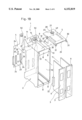
- FIG. 1A is a disassembled perspective view of a numerical control device of a first embodiment of the present invention
- FIG. 1B is a disassembled perspective view of a numerical control device of a second embodiment of the present invention.
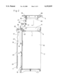
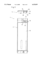
- FIG. 2 is a vertical cross section of the numerical control device of FIG. 1A;
- FIG. 3 is a vertical cross section of the numerical control device of FIG. 1A;
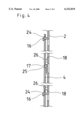
- FIG. 4 is a vertical cross section of the coupling portion between the wire distribution board and the box structure
- FIG. 5 is a top view of the first connector
- FIG. 6 is a front view of the connector of FIG. 5;
- FIG. 7 is a side view of the connector of FIG. 5;
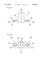
- FIG. 8 is a top view of the second connector
- FIG. 9 is a rear view of the second connector
- FIG. 10 is a side view of the second connector
- FIG. 11 shows the positional relationship between the mounting hole and bobbin-shaped member when the position of the second connector shifts.
- a numerical control device 1 of the present invention is comprised by a box structure 2, a board unit comprising a plurality of boards 3 such as a power supply board and control boards, housed within the box structure 2, a wire distribution board 4 for connecting the board unit, disposed on the rear surface of the box structure 2, a fan unit 5 detachably mounted on the top surface of the box structure 2, a first connector 20 secured to the box structure 2, and a second connector 21 mounted to the fan unit 5.
- box structure 2 is formed from a plastic formed body with a slight gap open from the upper edge of the structure with a top panel 6 being installed therein.
- a board accommodation space 10 is formed under the top panel 6 with a front surface that opens.
- the fan unit accommodation space 11 is formed over the top panel 6 with a top surface that opens and an opening portion 7 is cut out in the top panel 6 so that the board accommodation space 10 and the fan unit accommodation space 11 communicate.
- a plurality of guide channels 8 are formed along the front-to-back direction on the bottom surface and top surface of the board accommodation space 10.
- a front portion cover 9 of the plastic formed body is attached to the front edge of the board 3 to cover the front surface of the box structure 2.
- Slots 12 are cut out in the side walls which define the fan unit accommodation space 11 at portions near the rear wall to extend in the front-to-back direction, while generally L-shaped notches 13, the tips of which are bent towards the outside, are formed in both the front and rear wall which define the fan unit accommodation space 11 at portions near the side walls.
- a window portion 14 for setting a first connector 20 is cut out in the rear wall which defines the fan unit accommodation space 11.
- a snap coupling arm 42 protrudes towards the rear from a generally central portion of the window portion 14.
- the snap coupling arm 42 has an elasticity and is formed with a hook on its tip facing upward.
- the connector support protrusions 15 protrude towards the rear from both sides of the window portion 14.
- portions at four corners of the wall at the rear of the board accommodation space 10 are cut to erect rearward and the tip of each of these cut portions is bent downward to form a hook-shaped piece 16.
- a holding protrusion 17 protrudes from the center portion of the wall at the rear of the board accommodation space 10. This holding protrusion 17 has a tapered surface leaning towards the rear upward.
- a positioning protrusion 18 is attached at a suitable location on the rear surface of the box structure 2.
- the wire distribution board 4 functions to connect one board 3 to the other board 3, one board 3 to external devices, or one board unit to the other board units housed in other numerical control devices, and is detachably mounted to the wall at the rear of the board accommodation space 10, as shown in FIG. 1A.
- a power supply terminal 19 is disposed on the upper edge of the wire distribution board 4 and terminals 23 are disposed at suitable locations on the front surface of the wire distribution board 4. These terminals 23 are connected to the terminals 22 of each board 3.
- Openings 24 are cut out at the four corners of the wire distribution board 4 and hold the hook-shaped pieces 16 of the box structure 2.
- the positioning hole 26 is cut out at a position corresponding to the positioning protrusion 18.
- the through hole 25 is cut out at the center portion of the wire distribution board 4. This through hole 25 receives the holding protrusion 17 so that the wire distribution board 4 is fixed to the box structure 2.
- the wire distribution board 4 In order to mount wire distribution board 4 to the box structure 2, as shown in FIG. 4, the wire distribution board 4 is moved upward and then forward towards the box structure 2, and the hook-shaped pieces 16 and the holding protrusion 17 of the box structure 2 are coupled to the openings 24 and the through hole 25, respectively.
- the wire distribution board 4 presses against the tapered surface of the holding protrusion 17 to cause the holding protrusion 17 to bend forward, then the holding protrusion 17 opposes the through hole 25 and is fitted into the through hole 25 by means of elasticity of the holding protrusion 17.
- the fan unit 5 is comprises a cooling fan motor 29 mounted on the lower surface of the fan cover 28.
- Both side edge portions of the fan cover 28 are bent downward forming the side walls 30.
- the projections 31 extend outward from the outer surface of the lower edges at the front portion of these side walls 30. These projections 31 are coupled to the notches 13 of the box structure 2.
- portions near to the rear end on both sides of the side walls 30 are cut off at a suitable width so that an elastic arm 32 is formed at each side of the side wall 30.
- the protruding shafts 33 are formed at the outer surface of the lower edge of the elastic arms 32.
- the protruding shafts 33 are fitted into slots 12 of the box structure 2 by means of elasticity of the protruding shaft 33. That is, the protruding shaft 33 serves to engage the fan unit 5 with the box structure 2.
- a pair of left and right support pieces 34 protrudes downward at the rear portions of the fan cover 28, and the protruding portions 35 are formed at the rear surface of the lower edge of each support piece. These protruding portions 35 are formed at positions which correspond to the connector support protrusions 15 of the box structure 2.
- the fan unit 5 is mounted to the box structure in the following manner.
- the elastic arms 32 are slightly pressed inward and the side walls 30 of the fan unit 5 and the projections 31 are coupled to the notches 13 of the box structure 2. Then, the fan unit 5 is moved rearward from the front surface of the fan unit accommodation space 11.
- the first connector 20 is formed with securing pieces 38 protruding from both sides of the connector body 37.
- the insertion portions 36 which have terminals on their tips are disposed protruding from the front surface of the connector body 37.
- securing holes 39 are formed in the securing pieces 38.
- a relay cable 41 is drawn out from the connector body 37 and a third connector 43 is mounted to the tip of the relay cable 41.
- the third connector 43 is connected to the power supply terminal 19 of the wire distribution board 4.
- the first connector 20 is secured to the box structure 2 in the following manner.
- a snap coupling arm 42 is brought into contact with a center portion of the lower surface of the connector body 37 so that the insertion portions 36 of the first connector 20 may face the fan unit accommodation space 11 of the box structure 2.
- the connector body 37 is set in the window portion 14.
- the connector support protrusions 15 of the box structure 2 are each inserted through the securing holes 39 so as to secure the first connector 20.
- the first connector 20, securely mounted to the box structure 2 is electrically connected to the power supply terminal 19 through the relay cable 41.
- the second connector 21 comprises of the connector body 45 and securing pieces 48 protruding from both sides of the connector body 45.
- Receiving portions 44 are disposed on the rear surface of the connector body 45. These receiving portions 44 have terminals at their innermost areas and as shown in FIG. 8, the tips of the inner periphery surfaces of the receiving portions 44 are tapered with the tip direction slanting outwards in order to make it easy to insert insertion portions 36 of the first connector 20.
- mounting holes 46 are cut out in the securing pieces 48.
- the bobbin-shaped members 47 having bore diameters slightly smaller than those of the mounting holes 46 are inserted into the mounting holes 46 so that the sliding movement of the bobbin-shaped member 47 in the axial direction is restricted and further the bobbin-shaped members 47 are movable within a range of the cross-section of the mounting holes 46.
- the connector body 45 of the second connector 21 is electrically connected to the fan motor 29 through the lead wire 49.
- the second connector 21 is mounted to the fan unit 5.
- the receiving portions 44 of the second connector 21 are arranged at a position opposite the insertion portions 36 of the first connector 20, allowing the first connector 20 and the second connector 21 to be connected.
- the terminals of both make contact with each other so that drive power from the power supply terminal 19 of the wire distribution board 4 is supplied to the fan motor 29.
- the securing pieces 48 can also be moved relative to the protruding portions 35 which are inserted into the winding shape members 47. Therefore, the second connector 21 and the connector body 45 can move relative to each other.
- This embodiment is characterized in that the first connector 50 is directly disposed on the wire distribution board 4.
- the wire distribution board 4 has an upper extension portion which extends upward from the upper side thereof, and the first connector 50 is mounted to the upper extension portion of the wire distribution board 4 at the location corresponding to the window portion 14 which is formed at an upper portion of the rear wall of the box structure 2.
Landscapes
- Engineering & Computer Science (AREA)
- Microelectronics & Electronic Packaging (AREA)
- Aviation & Aerospace Engineering (AREA)
- Physics & Mathematics (AREA)
- Thermal Sciences (AREA)
- Insertion, Bundling And Securing Of Wires For Electric Apparatuses (AREA)
Applications Claiming Priority (2)
| Application Number | Priority Date | Filing Date | Title |
|---|---|---|---|
| JP10-114369 | 1998-04-10 | ||
| JP11436998 | 1998-04-10 |
Publications (1)
| Publication Number | Publication Date |
|---|---|
| US6152819A true US6152819A (en) | 2000-11-28 |
Family
ID=14635993
Family Applications (1)
| Application Number | Title | Priority Date | Filing Date |
|---|---|---|---|
| US09/288,697 Expired - Lifetime US6152819A (en) | 1998-04-10 | 1999-04-09 | Numerical control device |
Country Status (2)
| Country | Link |
|---|---|
| US (1) | US6152819A (de) |
| EP (1) | EP0949856A3 (de) |
Cited By (3)
| Publication number | Priority date | Publication date | Assignee | Title |
|---|---|---|---|---|
| US20070119049A1 (en) * | 2005-11-29 | 2007-05-31 | Seiko Epson Corporation | Robot control device and robot system |
| US20090263992A1 (en) * | 2008-04-21 | 2009-10-22 | International Business Machines Corporation | Blind Docking Electrical Connector |
| CN105960139A (zh) * | 2016-03-23 | 2016-09-21 | 杭州迪普科技有限公司 | 拉手条及具有其的通信设备 |
Families Citing this family (1)
| Publication number | Priority date | Publication date | Assignee | Title |
|---|---|---|---|---|
| ES2267464T3 (es) * | 2000-08-15 | 2007-03-16 | Cannon Technologies Ltd. | Armario con bandeja para equipo montada en la parte superior. |
Citations (13)
| Publication number | Priority date | Publication date | Assignee | Title |
|---|---|---|---|---|
| JPH04126000A (ja) * | 1990-09-17 | 1992-04-27 | Fujitsu Ltd | ファン取付構造 |
| US5142442A (en) * | 1990-11-13 | 1992-08-25 | Compaq Computer Corporation | Combined fan spacer and wire guide |
| US5208730A (en) * | 1991-06-27 | 1993-05-04 | Compaq Computer Corporation | Computer cooling fan vibration isolation apparatus |
| US5398161A (en) * | 1993-07-23 | 1995-03-14 | Excel, Inc. | Telecommunications switch chassis having housing with front and rear compartments divided by interior partition and removable cover over rear compartment |
| US5460441A (en) * | 1994-11-01 | 1995-10-24 | Compaq Computer Corporation | Rack-mounted computer apparatus |
| JPH0846379A (ja) * | 1994-08-04 | 1996-02-16 | Fujitsu Ltd | 冷却ファンの取付け構造 |
| JPH09199881A (ja) * | 1996-01-19 | 1997-07-31 | Oki Electric Ind Co Ltd | 電子機器用ファンユニット |
| US5680295A (en) * | 1995-11-13 | 1997-10-21 | Ast Research, Inc. | Ventilated backplane for mounting disk drives in computer systems |
| US5680294A (en) * | 1995-03-28 | 1997-10-21 | The Whitaker Corporation | Pluggable power supply for card cage |
| US5684674A (en) * | 1996-01-16 | 1997-11-04 | Micronics Computers Inc. | Circuit board mounting brackets with convective air flow apertures |
| US5831822A (en) * | 1997-01-07 | 1998-11-03 | Apple Computer, Inc. | Personal computer having quick-release cooling fan |
| US5927386A (en) * | 1998-08-24 | 1999-07-27 | Macase Industrial Group Ga., Inc. | Computer hard drive heat sink assembly |
| US6005770A (en) * | 1997-11-12 | 1999-12-21 | Dell U.S.A., L.P. | Computer and a system and method for cooling the interior of the computer |
Family Cites Families (1)
| Publication number | Priority date | Publication date | Assignee | Title |
|---|---|---|---|---|
| FR2586335B1 (fr) * | 1985-08-14 | 1989-04-28 | Snecma | Support de calculateur de turbomachine d'aviation |
-
1999
- 1999-04-09 EP EP99302775A patent/EP0949856A3/de not_active Withdrawn
- 1999-04-09 US US09/288,697 patent/US6152819A/en not_active Expired - Lifetime
Patent Citations (13)
| Publication number | Priority date | Publication date | Assignee | Title |
|---|---|---|---|---|
| JPH04126000A (ja) * | 1990-09-17 | 1992-04-27 | Fujitsu Ltd | ファン取付構造 |
| US5142442A (en) * | 1990-11-13 | 1992-08-25 | Compaq Computer Corporation | Combined fan spacer and wire guide |
| US5208730A (en) * | 1991-06-27 | 1993-05-04 | Compaq Computer Corporation | Computer cooling fan vibration isolation apparatus |
| US5398161A (en) * | 1993-07-23 | 1995-03-14 | Excel, Inc. | Telecommunications switch chassis having housing with front and rear compartments divided by interior partition and removable cover over rear compartment |
| JPH0846379A (ja) * | 1994-08-04 | 1996-02-16 | Fujitsu Ltd | 冷却ファンの取付け構造 |
| US5460441A (en) * | 1994-11-01 | 1995-10-24 | Compaq Computer Corporation | Rack-mounted computer apparatus |
| US5680294A (en) * | 1995-03-28 | 1997-10-21 | The Whitaker Corporation | Pluggable power supply for card cage |
| US5680295A (en) * | 1995-11-13 | 1997-10-21 | Ast Research, Inc. | Ventilated backplane for mounting disk drives in computer systems |
| US5684674A (en) * | 1996-01-16 | 1997-11-04 | Micronics Computers Inc. | Circuit board mounting brackets with convective air flow apertures |
| JPH09199881A (ja) * | 1996-01-19 | 1997-07-31 | Oki Electric Ind Co Ltd | 電子機器用ファンユニット |
| US5831822A (en) * | 1997-01-07 | 1998-11-03 | Apple Computer, Inc. | Personal computer having quick-release cooling fan |
| US6005770A (en) * | 1997-11-12 | 1999-12-21 | Dell U.S.A., L.P. | Computer and a system and method for cooling the interior of the computer |
| US5927386A (en) * | 1998-08-24 | 1999-07-27 | Macase Industrial Group Ga., Inc. | Computer hard drive heat sink assembly |
Cited By (9)
| Publication number | Priority date | Publication date | Assignee | Title |
|---|---|---|---|---|
| US20070119049A1 (en) * | 2005-11-29 | 2007-05-31 | Seiko Epson Corporation | Robot control device and robot system |
| US7769489B2 (en) * | 2005-11-29 | 2010-08-03 | Seiko Epson Corporation | Robot control device and robot system |
| US20100262285A1 (en) * | 2005-11-29 | 2010-10-14 | Seiko Epson Corporation | Robot control device and robot system |
| CN102626928A (zh) * | 2005-11-29 | 2012-08-08 | 精工爱普生株式会社 | 机器人控制装置以及机器人系统 |
| CN102626926A (zh) * | 2005-11-29 | 2012-08-08 | 精工爱普生株式会社 | 机器人控制装置以及机器人系统 |
| US8599555B2 (en) * | 2005-11-29 | 2013-12-03 | Seiko Epson Corporation | Robot control device and robot system |
| US20090263992A1 (en) * | 2008-04-21 | 2009-10-22 | International Business Machines Corporation | Blind Docking Electrical Connector |
| US7731524B2 (en) * | 2008-04-21 | 2010-06-08 | International Business Machines Corporation | Blind docking electrical connector |
| CN105960139A (zh) * | 2016-03-23 | 2016-09-21 | 杭州迪普科技有限公司 | 拉手条及具有其的通信设备 |
Also Published As
| Publication number | Publication date |
|---|---|
| EP0949856A2 (de) | 1999-10-13 |
| EP0949856A3 (de) | 2000-04-26 |
Similar Documents
| Publication | Publication Date | Title |
|---|---|---|
| US6257897B1 (en) | Wiring harness device for instrument panels | |
| US5128830A (en) | Integrated installation assembly with self aligning connector | |
| CA1117210A (en) | Modular panel construction for programmable controller | |
| US5773763A (en) | Mounting device for communication RJ elements (patch panel) which has a rear cable guide strip and a front cable guide ring | |
| US12302522B2 (en) | Housing for an electronic circuit which is arranged on a printed circuit board | |
| US4813885A (en) | Wiring harness connector retainer | |
| US6152819A (en) | Numerical control device | |
| US5764492A (en) | Radio device with radio shielding and method of manufacture | |
| EP0079805B1 (de) | Gehäuse für Fernmeldeeinrichtung | |
| US5323296A (en) | I/O device including circuit board non-rigidly supported by elastically deformable terminal pins extending from a connector strip | |
| JP2000031678A (ja) | 数値制御装置 | |
| CN219065622U (zh) | 一种组合式功能测试装置 | |
| US8705244B2 (en) | Projector and unit for projector | |
| JPH0968343A (ja) | 電気機器のハウジング構造 | |
| JP2860865B2 (ja) | コネクタの端子固定装置 | |
| CN222637687U (zh) | 控制装置、控制设备、工业机器人系统以及电路板模块 | |
| JP3822363B2 (ja) | 可動コネクタ | |
| CN215597457U (zh) | 空调室内机 | |
| CN222824311U (zh) | 一种接线端子及灯条 | |
| JP3399084B2 (ja) | プリント基板用コネクタの取付け構造 | |
| JPH065147U (ja) | コネクタ | |
| CN222464029U (zh) | 一种便于拆装的线缆固定装置 | |
| CN216903595U (zh) | 一种墙壁插座 | |
| CN212005984U (zh) | 电控盒组件和空调室外机 | |
| CN219083207U (zh) | 一种吸油烟机的电器盒安装结构及吸油烟机 |
Legal Events
| Date | Code | Title | Description |
|---|---|---|---|
| AS | Assignment |
Owner name: FANUC LTD., JAPAN Free format text: ASSIGNMENT OF ASSIGNORS INTEREST;ASSIGNORS:SASAKI, KAZUYUKI;HIRANO, KAZUHIKO;REEL/FRAME:009894/0857 Effective date: 19990405 |
|
| STCF | Information on status: patent grant |
Free format text: PATENTED CASE |
|
| FEPP | Fee payment procedure |
Free format text: PAYER NUMBER DE-ASSIGNED (ORIGINAL EVENT CODE: RMPN); ENTITY STATUS OF PATENT OWNER: LARGE ENTITY |
|
| FPAY | Fee payment |
Year of fee payment: 4 |
|
| FPAY | Fee payment |
Year of fee payment: 8 |
|
| FPAY | Fee payment |
Year of fee payment: 12 |