US6154105A - Surface acoustic wave device with specific electrode materials and quartz substrate euler angles - Google Patents
Surface acoustic wave device with specific electrode materials and quartz substrate euler angles Download PDFInfo
- Publication number
- US6154105A US6154105A US09/249,036 US24903699A US6154105A US 6154105 A US6154105 A US 6154105A US 24903699 A US24903699 A US 24903699A US 6154105 A US6154105 A US 6154105A
- Authority
- US
- United States
- Prior art keywords
- acoustic wave
- surface acoustic
- idt
- quartz substrate
- interdigital
- Prior art date
- Legal status (The legal status is an assumption and is not a legal conclusion. Google has not performed a legal analysis and makes no representation as to the accuracy of the status listed.)
- Expired - Lifetime
Links
Images


Classifications
-
- H—ELECTRICITY
- H03—ELECTRONIC CIRCUITRY
- H03H—IMPEDANCE NETWORKS, e.g. RESONANT CIRCUITS; RESONATORS
- H03H9/00—Networks comprising electromechanical or electro-acoustic elements; Electromechanical resonators
- H03H9/46—Filters
- H03H9/64—Filters using surface acoustic waves
- H03H9/6423—Means for obtaining a particular transfer characteristic
- H03H9/6433—Coupled resonator filters
- H03H9/6436—Coupled resonator filters having one acoustic track only
-
- H—ELECTRICITY
- H03—ELECTRONIC CIRCUITRY
- H03H—IMPEDANCE NETWORKS, e.g. RESONANT CIRCUITS; RESONATORS
- H03H9/00—Networks comprising electromechanical or electro-acoustic elements; Electromechanical resonators
- H03H9/02—Details
- H03H9/02535—Details of surface acoustic wave devices
- H03H9/02543—Characteristics of substrate, e.g. cutting angles
- H03H9/02551—Characteristics of substrate, e.g. cutting angles of quartz substrates
-
- H—ELECTRICITY
- H03—ELECTRONIC CIRCUITRY
- H03H—IMPEDANCE NETWORKS, e.g. RESONANT CIRCUITS; RESONATORS
- H03H9/00—Networks comprising electromechanical or electro-acoustic elements; Electromechanical resonators
- H03H9/25—Constructional features of resonators using surface acoustic waves
-
- H—ELECTRICITY
- H03—ELECTRONIC CIRCUITRY
- H03H—IMPEDANCE NETWORKS, e.g. RESONANT CIRCUITS; RESONATORS
- H03H9/00—Networks comprising electromechanical or electro-acoustic elements; Electromechanical resonators
- H03H9/46—Filters
- H03H9/64—Filters using surface acoustic waves
- H03H9/6423—Means for obtaining a particular transfer characteristic
- H03H9/6433—Coupled resonator filters
- H03H9/644—Coupled resonator filters having two acoustic tracks
- H03H9/6456—Coupled resonator filters having two acoustic tracks being electrically coupled
- H03H9/6459—Coupled resonator filters having two acoustic tracks being electrically coupled via one connecting electrode
Definitions
- the present invention relates to a surface acoustic wave device containing a quartz substrate and, more particularly, to a surface acoustic wave device which has excellent, stable resonant characteristics achieved by a unique combination of the quartz substrate and electrodes.
- a surface acoustic wave device containing a quartz substrate serving as a piezoelectric substrate is disclosed in Japanese Examined Patent Publication No. 61-45892.
- an interdigital transducer for transmission and reception of signals includes gold electrodes which are disposed on a quartz substrate.
- Au is used as a material for forming electrodes which defines the transducer IDT. This causes the cost of the device to significantly increase and also makes the process of forming the device extremely difficult.
- preferred embodiments of the present invention provide a surface acoustic wave device which is inexpensive, has an electrode structure that is easily formed, and has excellent, stable resonant characteristics.
- a surface acoustic wave device includes a quartz substrate having an angle ⁇ of Euler angles (0, ⁇ , 90°) which satisfies 122° ⁇ 131°, and an interdigital transducer made of an electrode material containing one of Ta and W and disposed on the quartz substrate.
- the surface acoustic wave device achieves excellent frequency temperature characteristics and resonant characteristics.
- Ta and W are inexpensive, as compared with gold electrodes, so that the cost of the surface acoustic wave device is significantly reduced.
- Au as compared with Au, either Ta and W is easily processed.
- the surface acoustic wave device according to preferred embodiments of the present invention has excellent resonant characteristics and is constructed so as to be formed with high stability and with high precision.
- the angle ⁇ of the Euler angles (0, ⁇ , 90°) is preferably between about 125° and about 128° so that the surface acoustic wave device has even more excellent resonant characteristics.
- the interdigital transducer may have an electrode finger cross width (aperture) of up to about 40 ⁇ where ⁇ represents the wavelength of a surface acoustic wave to be excited. In this case, an unnecessary spurious response caused in the lateral mode in the band is effectively inhibited, thereby obtaining excellent resonant characteristics.
- the angle ⁇ of the Euler angles preferably satisfies the following formula (1) in the case where the IDT is made of Ta, and the formula (2) in the case where the IDT is made of W, respectively:
- the frequency varying ratio can have a value of up to about 200 ppm in a temperature range from about -20° C. to about 80° C.
- the surface acoustic wave resonator may include reflectors arranged on the opposite sides of the transducer IDT in the surface acoustic wave propagation direction. Further, the number N IDT of the electrode finger pairs of the interdigital transducer and the number N REF of electrode fingers of the reflector may be adjusted as desired.
- the surface acoustic wave resonator according to preferred embodiments of the present invention can be successfully and easily incorporated in a surface acoustic wave filter or a longitudinally coupled device.
- FIG. 1 is an explanatory plan view of a surface acoustic wave device according to a preferred embodiment of the present invention.
- FIG. 2 is a graph illustrating a relationship between the change of the angle ⁇ of Euler angles (0, ⁇ , 90°) and the frequency temperature coefficient TCF when the angle ⁇ ' is in the range of about 125° to about 128°.
- FIG. 3 is a graph showing the resonant characteristics of the surface acoustic wave device of the preferred embodiment of the present invention shown in FIG. 1.
- FIG. 4 is a graph showing changes in impedance ratio when ⁇ is varied.
- FIG. 6 is a graph showing the relationship between d ⁇ (h/ ⁇ ) and ⁇ of the surface acoustic wave resonator of a preferred embodiment of the present invention having an electrode material which is Ta.
- FIG. 7 is a graph showing the relation between d ⁇ (h/ ⁇ ) and ⁇ of the surface acoustic wave resonator of a preferred embodiment of the present invention having an electrode material which is W.
- FIG. 8 is a graph showing the relationship between the frequency normalized by the resonant frequency and the impedance of the surface acoustic wave resonator of a preferred embodiment of the present invention having an electrode finger cross width (aperture) of the IDT of about 25 ⁇ .
- FIG. 9 is a graph showing the relationship between the frequency normalized by the resonant frequency and the impedance of the surface acoustic wave resonator of a preferred embodiment of the present invention having an electrode finger cross width of the IDT of about 40 ⁇ .
- FIG. 10 is a graph showing the relationship between the frequency normalized by the resonant frequency and the impedance of the surface acoustic wave resonator of a preferred embodiment of the present invention having an electrode finger cross width of the IDT of about 100 ⁇ .
- FIG. 11 is a graph showing the relationship between the number N IDT of electrode pairs of IDT and the impedance ratio of the surface acoustic wave resonator of a preferred embodiment of the present invention.
- FIG. 12 is a graph showing the relationship between the number N IDT of electrode pairs of IDT and the bandwidth ratio of the surface acoustic wave resonator of a preferred embodiment of the present invention.
- FIG. 13 is a graph showing the relationship between the number N IDT of electrode pairs of IDT and the resonant resistance of the surface acoustic wave resonator of a preferred embodiment of the present invention.
- FIG. 14 is a graph showing the relationship between the number N REF of electrode pairs and the impedance ratio of the surface acoustic wave resonator of a preferred embodiment of the present invention.
- FIG. 15 is a plan view of a longitudinally coupled surface acoustic wave filter according to another preferred embodiment of the present invention.
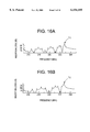
- FIGS. 16A and 16B are graphs of the insertion loss vs. frequency characteristics of the longitudinally coupled surface acoustic wave filter, obtained when N IDT is varied.
- FIG. 21 is a graph showing the relationship between the gap x between the transducers IDT and N IDT MAX of the longitudinally coupled surface acoustic wave filter of a preferred embodiment of the present invention.
- FIG. 22 is an explanatory plan view of a modified example of the longitudinally coupled surface acoustic wave filter of the present invention.
- FIG. 23 is a graph showing the relationship between the number N REF of electrode fingers and the insertion loss of the longitudinally coupled surface acoustic wave filter of a preferred embodiment of the present invention.
- FIG. 24 is a circuit diagram of a surface acoustic wave filter incorporating a plurality of surface acoustic wave resonators according to a preferred embodiment, in accordance with another preferred embodiment of the present invention.
- FIG. 1 is a plan view illustrating a surface acoustic wave resonator according to a first preferred embodiment of the present invention.
- a surface acoustic wave resonator 1 includes a quartz substrate 2.
- the angle ⁇ of Euler angles (0, ⁇ , 90°) preferably satisfies the formula:
- the IDT 3 is provided on the quartz substrate 2.
- the IDT 3 includes a pair of interdigital electrodes 3a and 3b.
- the electrode fingers of the interdigital electrodes 3a and 3b are inserted into the spaces between them.
- Grating type reflectors 4,5 having plural electrode fingers short-circuited at the opposite ends thereof, respectively, are arranged on the opposite sides of the IDT 3 along the surface acoustic wave propagation direction.
- the IDT 3 and the reflectors 4,5 are formed with tungsten (W).
- the IDT 3 and the reflectors 4, 5 are preferably formed on the quartz substrate 2 by a thin film forming method such as vapor depositing, CVD, plating, sputtering tungsten, and or other suitable method.
- the angle ⁇ of Euler angles (0, ⁇ , 90°) is preferably in a range of about 122° to about 131°. Accordingly, by utilizing an SH type surface acoustic wave, the bandwidth can be greatly increased. Thus, the allowance and tolerance for variations in the center frequency, caused by changes in temperature, can be greatly improved. This will be described below.
- a conventional ST cut X propagation quartz substrate used in many devices has good frequency-temperature characteristics.
- the electromechanical coefficient K 2 for a Raleigh wave is 0.14%.
- the electromechanical coefficient K 2 is 0.64%.
- a filter containing the surface acoustic wave resonator 1 constructed according to this preferred embodiment provides an allowance of ⁇ 90 KHz.
- the varying-ratio of the frequency per 1° C., required for the surface acoustic wave device containing a ST cut X propagation quartz substrate and using a Raleigh wave, is ⁇ 1 ppm/° C. or lower.
- an optimum cut angle at which the frequency-varying ratio for the change of temperature from about -20° C. to about 80° C., namely, for the temperature change of about 100° C., is up to about 100 ppm, that is, the ratio per 1° C. up to 1 ppm/° C., is ⁇ about 125° to about 128° where ⁇ is the following one of the Euler angles (0, ⁇ , 90°).
- the temperature characteristics of the surface acoustic wave resonator were measured by varying ⁇ ', taken as a standard angle, which is within the above range, in such a manner to be increased or decreased with respect to the standard angle.
- the results are shown in FIG. 2.
- ⁇ ' any angle that it is in the range of about 125° to about 128°.
- the frequency temperature coefficients are 15 ppm/° C. at ⁇ '+3° and -15 ppm/° C. at ⁇ '-3°. This indicates that the temperature characteristics required on an ordinary level can be realized at approximately 122° ⁇ 131°.
- the production error is about ⁇ 0.3°. Accordingly, a predetermined cut angle can be substantially realized.
- the production error is about ⁇ 2°, depending on exposure techniques. Accordingly, it is possible that if the desired cut angle is about 90°, the surface acoustic wave resonator actually produced will have a cut angle in the range of about 88° to about 92°.
- the production error with respect to the propagation direction does not exert a great influence over the characteristics. Accordingly, it should be noted that even if the propagation direction is shifted by about ⁇ 2°, the advantages of preferred embodiments of the present invention can still be obtained.
- FIG. 3 shows the impedance-frequency characteristics of the surface acoustic wave resonator 1 containing the quartz substrate having the above-described Euler angles.
- IDT 3 and the reflectors 4, 5 are made of tungsten as an electrode material, excellent resonant characteristics are still achieved.
- the surface acoustic wave resonator 1 having excellent resonant characteristics can be inexpensively provided.
- H/ ⁇ and d are set to be 0.015 and 0.6, respectively. It has been confirmed that the same characteristics are obtained by setting H/ ⁇ at a value of from 0.010 to 0.025 and d at a value of from 0.4 to 0.8.
- the inventors of the present invention made an examination of different ways to obtain a surface acoustic wave resonator having less temperature-dependent changes of the resonant characteristics, that is, the excellent temperature characteristics.
- (f-f 20 )/f 20 (ppm) represents the frequency varying ratio of the resonant frequency f, as measured at the standard temperature of about 20° C.
- the temperature at the apex of the curve is about 34° C.
- the frequency varying ratio of the resonant frequency in the range from about -20° C. to about 80° C. is approximately 99 ppm.
- FIG. 6 shows a relationship between d ⁇ (h/ ⁇ ) and ⁇ , obtained when the frequency varying ratio of the resonant frequency is constant in the temperature range from about -20° C. to about 80° C.
- solid lines A and B define the range where the frequency varying ratio of the resonant frequency is less than about 100 ppm.
- broken lines C and D define the range where the frequency varying ratio of the resonant frequency is less than about 200 ppm.
- the range defined by the broken lines C and D including the error can be expressed by the formula (1).
- the range defined by the solid lines A and B including the error can be expressed by the following formula (3):
- the surface acoustic wave resonator which achieves excellent temperature characteristics can be provided by setting ⁇ to satisfy the above-described range defined by the formula (1), more preferably, by the formula (3).
- FIG. 7 is a graph corresponding to that of FIG. 6 except that W is used for the electrode material, which illustrates the relationship between d ⁇ (h/ ⁇ ) and ⁇ , obtained when the frequency varying ratio of the resonant frequency is constant in the temperature range from about -20° C. to about 80° C.
- solid lines E and F define the range where the frequency varying ratio of the resonant frequency has a value up to about 100 ppm.
- Broken lines G and H define the range where the frequency varying ratio of the resonant frequency has a value up to about 200 ppm.
- the surface acoustic wave resonator 1 having a varying ratio of the resonant frequency in the range from about -20° C. to about 80° C. of up to about 200 ppm, more preferably, up to about 100 ppm can be provided by setting the angle ⁇ to be in the range satisfying the formula (2), more preferably, the formula (4).
- the IDT 3 and the reflectors 4,5 are formed with tungsten or tantalum.
- the IDT 3 only may be formed with tungsten or tantalum.
- the IDT 3 may have the structure in which a thin film of another metallic material is laminated onto the W or Ta.
- the inventors of the present invention discovered that, in the surface acoustic wave device having a transducer IDT made of an electrode material containing Ta or W and disposed on the quartz substrate having the particular Euler angles, a spurious response caused in the lateral mode is greatly inhibited by setting the cross width of the electrode fingers of the IDT to be about 40 ⁇ or shorter.
- FIGS. 8, 9, and 10 show the results obtained at electrode finger cross widths of 25 ⁇ , 40 ⁇ , and 100 ⁇ , respectively.
- the spurious response caused by the higher mode vibration is greatly inhibited by setting the electrode finger cross width to be about 40 ⁇ or shorter.
- a spurious response in the frequency band is effectively inhibited by setting the electrode finger cross width of the transducer IDT to about 40 ⁇ or shorter. This provides excellent resonant characteristics.
- the configuration for achieving excellent temperature characteristics by adjusting the angle ⁇ and inhibiting the spurious response in the frequency band by setting the electrode finger cross width to be about 40 ⁇ or shorter can be applied to the other surface acoustic wave devices such as a surface acoustic wave filter, not only to the above-described surface acoustic wave resonator 1. In this case, excellent effects are also achieved.
- the inventors of the present invention made an examination of how the characteristics of the surface acoustic wave resonator 1 having the reflectors arranged on the opposite sides of the transducer IDT, as shown in FIG. 1, are affected by the number N IDT of electrode finger pairs of IDT.
- the impedance ratio of the obtained plural types of the surface acoustic wave resonators was measured by varying the number N IDT of electrode fingers of IDT. The results are shown in FIG. 11.
- the impedance ratio is defined as a value calculated according to 20 log(ra/ro) where ro and ra represent the resonant resistance and the anti-resonant resistance, respectively.
- the impedance ratio is increased with the number N IDT .
- the impedance ratio becomes saturated.
- the surface acoustic wave device having an appropriate impedance ratio can be obtained.
- the surface acoustic wave resonator having the transducer IDT made of Ta disposed on the quartz substrate with the above particular Euler angles in accordance with preferred embodiments of the present invention the surface acoustic wave resonator having an appropriate impedance ratio can be easily provided by setting the pair number of IDTs to be 200 or smaller. Thus, desired excellent characteristics can be easily realized.
- the inventors of the present invention measured the bandwidth ratio (fa-fr)/fr and the resonant resistance ro of the surface acoustic wave resonator 1 at different numbers N IDT . The results are shown in FIGS. 12 and 13, respectively.
- the bandwidth ratio is reduced as the number N IDT increases.
- the bandwidth ratio becomes substantially constant. Accordingly, when the number N IDT is set to have a value up to 20, the band width ratio can be easily controlled by adjusting the number N IDT .
- the resonance resistance is reduced as the number N IDT increases.
- the resonant resistance becomes substantially constant. Accordingly, it is seen in FIG. 13 that when N IDT is set to have a value up to 100, the resonant resistance can be easily controlled by adjusting the number N IDT .
- the resonant resistance and the band width ratio can be easily controlled by adjusting the number N IDT . More particularly, the resonant resistance can be easily controlled by adjusting the number N IDT if it is in the range of up to 100, while the desired bandwidth ratio can be easily achieved by adjusting the number N IDT if it is in the range of up to 20.
- FIG. 14 shows the results. The number N REF of electrode fingers of the reflector is plotted on the abscissa in FIG. 14 and the impedance ratio is plotted on the ordinate.
- the impedance ratio tends to increase, irrespective of the number N REF .
- the number N REF exceeds 20, the rising of the impedance ratio becomes saturated.
- the impedance ratio can be easily controlled by adjusting the number of N REF .
- the impedance ratio can be easily controlled by adjusting the number N REF if it is less than or equal to 20. In this manner, desired excellent characteristics can be certainly obtained.
- the surface acoustic wave filter may be constructed by using a plurality of the above-described surface acoustic wave resonators 1.
- the configuration of the surface acoustic wave filter is not particularly restricted.
- a plurality of surface acoustic wave resonators 1 may be arranged in series arms and parallel arms, as series arm resonators S1 through S3 and parallel arm resonators P1 through P4, to define a ladder type filter. That is, the present invention may be applied to a surface acoustic wave filter made up of plural surface acoustic wave resonators.
- a longitudinally coupled surface acoustic wave filter may be constructed by arranging two interdigital transducer IDTs between the reflectors, as described below with reference with FIGS. 15 and 22.
- FIG. 15 is a schematic plan view of a surface acoustic wave filter according to a another preferred embodiment of the present invention.
- the surface acoustic wave filter 11 is preferably formed by using a quartz substrate 12.
- the angle ⁇ of Euler angles (0, ⁇ , 90°) preferably satisfies the following formula: 125° ⁇ ° ⁇ 128°, as with the surface acoustic wave resonator of the first preferred embodiment.
- first, second interdigital transducer IDTs 13, 14 are provided on the quartz substrate 12, first, second interdigital transducer IDTs 13, 14 are provided.
- the transducer IDTs 13, 14 have a pair of interdigital electrodes 13a, 13b, and a pair of interdigital electrodes 14a, 14b, respectively.
- the electrode fingers of a pair of the interdigital electrodes 13a, 13b are inserted into the spaces between them.
- the electrode fingers of a pair of the interdigital electrodes 14a, 14b are inserted into the spaces between them.
- the transducer IDTs 13, 14 are arranged so as to be separated from each other by a gap G along the surface acoustic wave propagation direction.
- Grating type reflectors 15, 16 to which the plural electrode fingers are short-circuited at the ends thereof are arranged on the opposite sides of the region where the transducers IDT 13, 14 are provided, in the surface acoustic wave propagation direction.
- the above transducers IDT 13, 14 and the reflectors 15, 16 are preferably made of tungsten or tantalum.
- the surface acoustic wave of this preferred embodiment is characteristic in that, in addition to the above-described particular quartz substrate and the transducers IDT 13, 14 made of an electrode material containing one of Ta and W, the respective numbers N IDT of electrode finger pairs of the first, second transducers IDT 13, 14 are set to be up to N IDT MAX (x) which is a value defined as follows.
- n is an integer defined in accordance with:
- the number N IDT is set to be up to the above-described N IDT MAX . Accordingly, the mode interval (ratio (%) of the difference in frequency between the longitudinal fundamental mode and the longitudinal higher-order mode to the center frequency) can be controlled as described below, and thereby, the bandwidth can be adjusted. This will be described with reference to FIGS. 16 through 21.
- FIGS. 16A and 16B show the insertion loss-frequency characteristics of the surface acoustic wave filter 11 in which the gap between the first IDT 13 and the second IDT 14 is about 0.50 ⁇ , the numbers N IDT are 50 (for FIG. 16A) and 30 (for FIG. 16B), the number N REF is 40, and the respective gaps between the reflectors 15, 16 and the transducers IDT 13, 14 adjacent thereto along the surface acoustic wave propagation direction are about 0.50 ⁇ , and the load impedance is about 50 ⁇ .
- the characteristics in FIGS. 16A and 16B and FIGS. 17 through 20 described below were obtained under the condition that the quartz substrate having the Euler angles (0, 127°, 90°) is used, the film thickness h/ ⁇ of the transducers IDT 13, 14 is about 0.02, and d is about 0.6.
- the frequency bands to be used are indicated by arrows L 1 and L 2 .
- the bandwidths become different by varying the values of N IDT .
- the difference between the above bandwidths is a phenomenon caused by the overlap of the fundamental mode and the higher order mode. Accordingly, the inventors of the present invention made an investigation concerning how the ratio, namely, the bandwidth, of the frequency difference (mode frequency difference) between the higher order mode and the fundamental mode to the center frequency is changed with the number N IDT . The results are shown in FIGS. 17 through 20.
- FIGS. 17, 18, 19 and 20 show the characteristics measured when a gap x between IDTs 13, 14 has a value of 0.20 ⁇ , 0.50 ⁇ , 0.70 ⁇ , and 0.90 ⁇ , respectively.
- the filter characteristics having a bandwidth can be obtained by setting N IDT to have a value up to the constant value. Further, a desired bandwidth can be realized by adjusting the number N IDT in the range of the above-described constant value and lower.
- N IDT MAX (X) which is the number N IDT positioning on the curve M
- N IDT MAX (X) which is the number N IDT positioning on the curve M
- n satisfies 0.22+0.55n-(0.55/2) ⁇ x ⁇ 0.22+0.55n+(0.55/2), that is:
- n is an integer satisfying the above formula (6).
- N IDT MAX the value N IDT MAX (x) depends on n, as indicated by the formula (5).
- a bandwidth can be obtained by setting the number N IDT , which is the number of electrode pairs of the transducers IDT 13, 14, to be up to the value N IDT MAX (x) defined as described above, and a desired bandwidth can be easily realized by adjusting the number N IDT in the above-described range.
- the above-described insertion loss is affected by the numbers of electrode finger pairs of the transducers IDT 13, 14 and the size of the gap G between IDT 13, 14. Accordingly, different types of the surface acoustic wave filters 11 having the different numbers of electrode finger pairs of IDT 13, 14 and different gaps G between IDTs 13, 14 were produced. The insertion loss was measured. FIG. 23 illustrates the results.
- the insertion loss can be controlled by adjusting the number N REF if it has a value of up to 20. That is, the surface acoustic wave filter 11 having a desired insertion loss can be easily provided by adjusting the number N REF .
- the surface acoustic wave filter 11 of FIG. 15 is a longitudinally coupled surface acoustic wave filter containing the first IDT 13 and the second IDT 14.
- the longitudinally coupled surface acoustic wave filter of preferred embodiments of the present invention may have a configuration with a pole number of at least two.
- FIG. 22 is a plan view showing the electrode configuration of a longitudinally coupled surface acoustic wave filter which is formed by longitudinally connecting two of the longitudinally coupled surface acoustic wave filters 11 as shown in FIG. 15.
- a first interdigital transducer 23 and a second interdigital transducer 24 are made of Ta or W and disposed on the quartz substrate with the desired Euler angles. Reflectors 25, 26 are disposed on the opposite sides of the region where IDTs 23, 24 are provided, in the surface acoustic wave propagation direction. Further, a first interdigital transducer 27 and a second interdigital transducer 28 are provided on one side of the region where IDTs 23, 24 are provided. Reflectors 29, 30 are disposed on the opposite sides of the region where IDTs 27, 28 are provided, in the surface acoustic wave propagation direction.
- the transducers IDT 23, 24, 27, and 28 have paired interdigital electrodes 23a and 23b, 24a and 24b, 27a and 27b, and 28a and 28b, respectively.
- the surface acoustic wave filter having a configuration with the pole number of two is formed in which a surface acoustic wave filter section made up of IDTs 23, 24 and the reflectors 25, 26, and a surface acoustic wave filter section made up of IDTs 27, 28 and the reflectors 29, 30 are connected to each other.
- one interdigital electrode 23a of the IDT 23 is connected to ground, while the other interdigital electrode 23b is electrically connected to one interdigital electrode 28a of IDT 28.
- the other interdigital electrode 28b of IDT 28 is electrically connected to ground.
Landscapes
- Physics & Mathematics (AREA)
- Acoustics & Sound (AREA)
- Surface Acoustic Wave Elements And Circuit Networks Thereof (AREA)
Applications Claiming Priority (4)
| Application Number | Priority Date | Filing Date | Title |
|---|---|---|---|
| JP3312198 | 1998-02-16 | ||
| JP10-033121 | 1998-02-16 | ||
| JP00419799A JP3301399B2 (ja) | 1998-02-16 | 1999-01-11 | 弾性表面波装置 |
| JP11-004197 | 1999-01-11 |
Publications (1)
| Publication Number | Publication Date |
|---|---|
| US6154105A true US6154105A (en) | 2000-11-28 |
Family
ID=26337928
Family Applications (1)
| Application Number | Title | Priority Date | Filing Date |
|---|---|---|---|
| US09/249,036 Expired - Lifetime US6154105A (en) | 1998-02-16 | 1999-02-12 | Surface acoustic wave device with specific electrode materials and quartz substrate euler angles |
Country Status (8)
| Country | Link |
|---|---|
| US (1) | US6154105A (de) |
| EP (1) | EP0936733B1 (de) |
| JP (1) | JP3301399B2 (de) |
| KR (1) | KR100317924B1 (de) |
| CN (1) | CN1136654C (de) |
| DE (1) | DE69926672T2 (de) |
| SG (1) | SG73613A1 (de) |
| TW (1) | TW441175B (de) |
Cited By (27)
| Publication number | Priority date | Publication date | Assignee | Title |
|---|---|---|---|---|
| US6353371B1 (en) * | 1999-03-08 | 2002-03-05 | Murata Manufacturing Co., Ltd | Transversely coupled resonator type surface acoustic wave filter and longitudinally coupled resonator type surface acoustic wave filter |
| US6437668B1 (en) * | 1999-05-07 | 2002-08-20 | Murata Manufacturing Co., Ltd. | Surface acoustic wave resonator, surface acoustic wave device, and communication device using shear horizontal waves |
| US20020195905A1 (en) * | 1999-05-27 | 2002-12-26 | Murata Manufacturing Co., Ltd. | Surface acoustic wave device and method of producing the same |
| US20030090341A1 (en) * | 2001-10-25 | 2003-05-15 | Murata Manufacturing Co., Ltd. | Longitudinally coupled surface acoustic wave resonator filter |
| US20030146674A1 (en) * | 2002-02-01 | 2003-08-07 | Philippe Jacot | Surface acoustic wave device having improved performance and method of making the device |
| US20030146810A1 (en) * | 2001-12-28 | 2003-08-07 | Seiko Epson Corporation | Surface acoustic wave device and communications apparatus using the same |
| US20040164645A1 (en) * | 2002-12-18 | 2004-08-26 | Seiko Epson Corporation | Surface acoustic wave device, method of manufacturing the same, and electronic apparatus |
| US6946930B2 (en) * | 2001-04-27 | 2005-09-20 | Murata Manufacturing Co., Ltd. | Surface acoustic wave device and electronic device using the same |
| US7009468B2 (en) * | 2001-04-27 | 2006-03-07 | Murata Manufacturing Co., Ltd. | Surface acoustic wave device and electronic device using the same |
| US20060145569A1 (en) * | 2005-01-06 | 2006-07-06 | Epson Toyocom Corporation | Surface acoustic wave device |
| US20090206955A1 (en) * | 2008-02-20 | 2009-08-20 | Epson Toyocom Corporation | Surface acoustic wave device and surface acoustic wave oscillator |
| US20090237181A1 (en) * | 2006-12-27 | 2009-09-24 | Murata Manufacturing Co., Ltd. | Surface acoustic wave device |
| US20100219913A1 (en) * | 2009-02-27 | 2010-09-02 | Epson Toyocom Corporation | Surface acoustic wave resonator and surface acoustic wave oscillator |
| US20100244626A1 (en) * | 2009-02-27 | 2010-09-30 | Epson Toyocom Corporation | Surface acoustic wave resonator, surface acoustic wave oscillator, and electronic instrument |
| US8471434B2 (en) | 2010-08-26 | 2013-06-25 | Seiko Epson Corporation | Surface acoustic wave device, surface acoustic wave oscillator, and electronic apparatus |
| US8476984B2 (en) | 2010-12-07 | 2013-07-02 | Seiko Epson Corporation | Vibration device, oscillator, and electronic apparatus |
| US20130257562A1 (en) * | 2010-09-28 | 2013-10-03 | Epcos Ag | Acoustic wave filter having reduced non-linearities, and method for production |
| US8598766B2 (en) | 2010-12-03 | 2013-12-03 | Seiko Epson Corporation | Surface acoustic wave resonator, surface acoustic wave oscillator, and electronic apparatus |
| US8692439B2 (en) | 2010-08-26 | 2014-04-08 | Seiko Epson Corporation | Surface acoustic wave resonator, surface acoustic wave oscillator, and electronic device |
| US8928432B2 (en) | 2010-08-26 | 2015-01-06 | Seiko Epson Corporation | Surface acoustic wave resonator, surface acoustic wave oscillator, and electronic apparatus |
| US9048806B2 (en) | 2010-09-09 | 2015-06-02 | Seiko Epson Corporation | Surface acoustic wave device, electronic apparatus, and sensor apparatus |
| US9088263B2 (en) | 2010-06-17 | 2015-07-21 | Seiko Epson Corporation | Surface acoustic wave resonator, surface acoustic wave oscillator, and electronic apparatus |
| US11121700B2 (en) * | 2018-11-20 | 2021-09-14 | Murata Manufacturing Co., Ltd. | Filter and multiplexer |
| US20220278667A1 (en) * | 2019-12-09 | 2022-09-01 | Murata Manufacturing Co., Ltd. | Acoustic wave device |
| US20240413806A1 (en) * | 2018-10-01 | 2024-12-12 | Qorvo Us, Inc. | Wave apodization for guided saw resonators |
| US12191839B2 (en) | 2020-02-06 | 2025-01-07 | Murata Manufacturing Co., Ltd. | Acoustic wave device |
| WO2025241430A1 (zh) * | 2024-05-21 | 2025-11-27 | 无锡市好达电子股份有限公司 | 弹性波装置 |
Families Citing this family (6)
| Publication number | Priority date | Publication date | Assignee | Title |
|---|---|---|---|---|
| JP3435638B2 (ja) | 2000-10-27 | 2003-08-11 | 株式会社村田製作所 | 弾性表面波装置及びその製造方法 |
| JP2006295311A (ja) * | 2005-04-06 | 2006-10-26 | Seiko Epson Corp | 弾性表面波素子片および弾性表面波装置 |
| JP4645957B2 (ja) * | 2006-09-29 | 2011-03-09 | セイコーエプソン株式会社 | 弾性表面波素子片および弾性表面波装置 |
| JP4582150B2 (ja) * | 2008-01-11 | 2010-11-17 | エプソントヨコム株式会社 | 弾性表面波デバイスとこれを用いたモジュール装置又は発振回路 |
| JP2011223473A (ja) * | 2010-04-13 | 2011-11-04 | Seiko Epson Corp | 振動片、振動子および圧電デバイス |
| KR20210068131A (ko) * | 2018-10-16 | 2021-06-08 | 도호쿠 다이가쿠 | 음향파 디바이스들 |
Citations (10)
| Publication number | Priority date | Publication date | Assignee | Title |
|---|---|---|---|---|
| JPS6145892A (ja) * | 1984-08-04 | 1986-03-05 | ロツラー ゲゼルシヤフト ミト ベシユレンクテル ハフツング ウント コンパニー シユペツイアール フアブリーク フユア ザイルヴインデン ウント ヘーベツオイゲ | 連続巻上げ機 |
| US5392013A (en) * | 1992-07-17 | 1995-02-21 | Nec Corporation | Surface acoustic wave filter capable of widening a bandwidth |
| GB2288503A (en) * | 1994-04-13 | 1995-10-18 | Murata Manufacturing Co | Saw filter |
| WO1997025776A1 (en) * | 1996-01-10 | 1997-07-17 | Sawtek, Inc. | High frequency saw device |
| US5729186A (en) * | 1995-04-12 | 1998-03-17 | Matsushita Electric Industrial Co., Ltd. | Resonator ladder surface acoustic wave filter suppressing spurious signals |
| JPH10224172A (ja) * | 1997-02-07 | 1998-08-21 | Murata Mfg Co Ltd | 表面波装置 |
| EP0860943A2 (de) * | 1997-02-20 | 1998-08-26 | Murata Manufacturing Co., Ltd. | Akustische Oberflächenwellenanordnung |
| US5831493A (en) * | 1995-08-14 | 1998-11-03 | Murata Manufacturing Co., Ltd. | Surface acoustic wave ladder filter utilizing a generated spurious component of the parallel arm |
| US5847486A (en) * | 1994-10-19 | 1998-12-08 | Murata Manufacturing Co., Ltd. | Love-wave device including a thin film of TA or W |
| US5850167A (en) * | 1995-04-11 | 1998-12-15 | Kinseki, Limited | Surface acoustic wave device |
Family Cites Families (6)
| Publication number | Priority date | Publication date | Assignee | Title |
|---|---|---|---|---|
| GB1451326A (en) * | 1973-02-16 | 1976-09-29 | Nat Res Dev | Acoustic wave devices |
| JPS55105425A (en) * | 1979-02-06 | 1980-08-13 | Fujitsu Ltd | Elastic surface wave device |
| JPS61195013A (ja) * | 1985-02-25 | 1986-08-29 | Yasuhiko Nakagawa | 零温度係数をもつ弾性表面波材料 |
| JP2645674B2 (ja) * | 1990-10-15 | 1997-08-25 | 国際電気株式会社 | 弾性表面波共振子 |
| JP3255502B2 (ja) * | 1993-07-26 | 2002-02-12 | 東洋通信機株式会社 | 高安定弾性表面波素子 |
| JPH08274577A (ja) * | 1995-03-31 | 1996-10-18 | Toko Inc | 表面弾性波多重モードフィルタとそのインピーダンス調整方法 |
-
1999
- 1999-01-11 JP JP00419799A patent/JP3301399B2/ja not_active Expired - Lifetime
- 1999-02-09 TW TW088101952A patent/TW441175B/zh not_active IP Right Cessation
- 1999-02-12 US US09/249,036 patent/US6154105A/en not_active Expired - Lifetime
- 1999-02-13 KR KR1019990005212A patent/KR100317924B1/ko not_active Expired - Lifetime
- 1999-02-14 CN CNB991034384A patent/CN1136654C/zh not_active Expired - Lifetime
- 1999-02-15 SG SG1999000618A patent/SG73613A1/en unknown
- 1999-02-16 DE DE69926672T patent/DE69926672T2/de not_active Expired - Lifetime
- 1999-02-16 EP EP99400361A patent/EP0936733B1/de not_active Expired - Lifetime
Patent Citations (11)
| Publication number | Priority date | Publication date | Assignee | Title |
|---|---|---|---|---|
| JPS6145892A (ja) * | 1984-08-04 | 1986-03-05 | ロツラー ゲゼルシヤフト ミト ベシユレンクテル ハフツング ウント コンパニー シユペツイアール フアブリーク フユア ザイルヴインデン ウント ヘーベツオイゲ | 連続巻上げ機 |
| US5392013A (en) * | 1992-07-17 | 1995-02-21 | Nec Corporation | Surface acoustic wave filter capable of widening a bandwidth |
| GB2288503A (en) * | 1994-04-13 | 1995-10-18 | Murata Manufacturing Co | Saw filter |
| US5847486A (en) * | 1994-10-19 | 1998-12-08 | Murata Manufacturing Co., Ltd. | Love-wave device including a thin film of TA or W |
| US5850167A (en) * | 1995-04-11 | 1998-12-15 | Kinseki, Limited | Surface acoustic wave device |
| US5729186A (en) * | 1995-04-12 | 1998-03-17 | Matsushita Electric Industrial Co., Ltd. | Resonator ladder surface acoustic wave filter suppressing spurious signals |
| US5831493A (en) * | 1995-08-14 | 1998-11-03 | Murata Manufacturing Co., Ltd. | Surface acoustic wave ladder filter utilizing a generated spurious component of the parallel arm |
| WO1997025776A1 (en) * | 1996-01-10 | 1997-07-17 | Sawtek, Inc. | High frequency saw device |
| JPH10224172A (ja) * | 1997-02-07 | 1998-08-21 | Murata Mfg Co Ltd | 表面波装置 |
| EP0860943A2 (de) * | 1997-02-20 | 1998-08-26 | Murata Manufacturing Co., Ltd. | Akustische Oberflächenwellenanordnung |
| US5953433A (en) * | 1997-02-20 | 1999-09-14 | Murata Manufacturing Co., Ltd. | Surface acoustic wave device |
Cited By (45)
| Publication number | Priority date | Publication date | Assignee | Title |
|---|---|---|---|---|
| US6353371B1 (en) * | 1999-03-08 | 2002-03-05 | Murata Manufacturing Co., Ltd | Transversely coupled resonator type surface acoustic wave filter and longitudinally coupled resonator type surface acoustic wave filter |
| US6437668B1 (en) * | 1999-05-07 | 2002-08-20 | Murata Manufacturing Co., Ltd. | Surface acoustic wave resonator, surface acoustic wave device, and communication device using shear horizontal waves |
| US20020195905A1 (en) * | 1999-05-27 | 2002-12-26 | Murata Manufacturing Co., Ltd. | Surface acoustic wave device and method of producing the same |
| US6928720B2 (en) * | 1999-05-27 | 2005-08-16 | Murata Manufacturing Co., Ltd. | Method of manufacturing a surface acoustic wave device |
| US6946930B2 (en) * | 2001-04-27 | 2005-09-20 | Murata Manufacturing Co., Ltd. | Surface acoustic wave device and electronic device using the same |
| US7009468B2 (en) * | 2001-04-27 | 2006-03-07 | Murata Manufacturing Co., Ltd. | Surface acoustic wave device and electronic device using the same |
| US20030090341A1 (en) * | 2001-10-25 | 2003-05-15 | Murata Manufacturing Co., Ltd. | Longitudinally coupled surface acoustic wave resonator filter |
| US6812812B2 (en) * | 2001-10-25 | 2004-11-02 | Murata Manufacturing Co., Ltd. | Longitudinally coupled surface acoustic wave resonator filter |
| US20030146810A1 (en) * | 2001-12-28 | 2003-08-07 | Seiko Epson Corporation | Surface acoustic wave device and communications apparatus using the same |
| US6856218B2 (en) * | 2001-12-28 | 2005-02-15 | Seiko Epson Corporation | Surface acoustic wave device and communications apparatus using the same |
| US20030146674A1 (en) * | 2002-02-01 | 2003-08-07 | Philippe Jacot | Surface acoustic wave device having improved performance and method of making the device |
| US7148610B2 (en) | 2002-02-01 | 2006-12-12 | Oc Oerlikon Balzers Ag | Surface acoustic wave device having improved performance and method of making the device |
| US20040164645A1 (en) * | 2002-12-18 | 2004-08-26 | Seiko Epson Corporation | Surface acoustic wave device, method of manufacturing the same, and electronic apparatus |
| US20060145569A1 (en) * | 2005-01-06 | 2006-07-06 | Epson Toyocom Corporation | Surface acoustic wave device |
| US7463119B2 (en) * | 2005-01-06 | 2008-12-09 | Epson Toyocom Corporation | Surface acoustic wave device |
| US7626314B2 (en) | 2006-12-27 | 2009-12-01 | Murata Manufacturing Co., Ltd. | Surface acoustic wave device |
| US20090237181A1 (en) * | 2006-12-27 | 2009-09-24 | Murata Manufacturing Co., Ltd. | Surface acoustic wave device |
| US8237326B2 (en) | 2008-02-20 | 2012-08-07 | Seiko Epson Corporation | Surface acoustic wave device and surface acoustic wave oscillator |
| US8084918B2 (en) | 2008-02-20 | 2011-12-27 | Seiko Epson Corporation | Surface acoustic wave device and surface acoustic wave oscillator |
| US20090206955A1 (en) * | 2008-02-20 | 2009-08-20 | Epson Toyocom Corporation | Surface acoustic wave device and surface acoustic wave oscillator |
| US8063534B2 (en) | 2008-02-20 | 2011-11-22 | Seiko Epson Corporation | Surface acoustic wave device and surface acoustic wave oscillator |
| US8502625B2 (en) | 2009-02-27 | 2013-08-06 | Seiko Epson Corporation | Surface acoustic wave resonator and surface acoustic wave oscillator |
| US20100244626A1 (en) * | 2009-02-27 | 2010-09-30 | Epson Toyocom Corporation | Surface acoustic wave resonator, surface acoustic wave oscillator, and electronic instrument |
| US8305162B2 (en) | 2009-02-27 | 2012-11-06 | Seiko Epson Corporation | Surface acoustic wave resonator and surface acoustic wave oscillator |
| US9762207B2 (en) | 2009-02-27 | 2017-09-12 | Seiko Epson Corporation | Surface acoustic wave resonator, surface acoustic wave oscillator, and electronic instrument |
| US20100219913A1 (en) * | 2009-02-27 | 2010-09-02 | Epson Toyocom Corporation | Surface acoustic wave resonator and surface acoustic wave oscillator |
| US8933612B2 (en) | 2009-02-27 | 2015-01-13 | Seiko Epson Corporation | Surface acoustic wave resonator, surface acoustic wave oscillator, and electronic instrument |
| US8952596B2 (en) | 2009-02-27 | 2015-02-10 | Seiko Epson Corporation | Surface acoustic wave resonator, surface acoustic wave oscillator, and electronic instrument |
| US9537464B2 (en) | 2010-06-17 | 2017-01-03 | Seiko Epson Corporation | Surface acoustic wave resonator, surface acoustic wave oscillator, and electronic apparatus |
| US9088263B2 (en) | 2010-06-17 | 2015-07-21 | Seiko Epson Corporation | Surface acoustic wave resonator, surface acoustic wave oscillator, and electronic apparatus |
| US8471434B2 (en) | 2010-08-26 | 2013-06-25 | Seiko Epson Corporation | Surface acoustic wave device, surface acoustic wave oscillator, and electronic apparatus |
| US8692439B2 (en) | 2010-08-26 | 2014-04-08 | Seiko Epson Corporation | Surface acoustic wave resonator, surface acoustic wave oscillator, and electronic device |
| US8928432B2 (en) | 2010-08-26 | 2015-01-06 | Seiko Epson Corporation | Surface acoustic wave resonator, surface acoustic wave oscillator, and electronic apparatus |
| US9048806B2 (en) | 2010-09-09 | 2015-06-02 | Seiko Epson Corporation | Surface acoustic wave device, electronic apparatus, and sensor apparatus |
| US9231556B2 (en) * | 2010-09-28 | 2016-01-05 | Epcos Ag | Acoustic wave filter having reduced non-linearities, and method for production |
| US20130257562A1 (en) * | 2010-09-28 | 2013-10-03 | Epcos Ag | Acoustic wave filter having reduced non-linearities, and method for production |
| US8791621B2 (en) | 2010-12-03 | 2014-07-29 | Seiko Epson Corporation | Surface acoustic wave resonator, surface acoustic wave oscillator, and electronic apparatus |
| US8598766B2 (en) | 2010-12-03 | 2013-12-03 | Seiko Epson Corporation | Surface acoustic wave resonator, surface acoustic wave oscillator, and electronic apparatus |
| US8476984B2 (en) | 2010-12-07 | 2013-07-02 | Seiko Epson Corporation | Vibration device, oscillator, and electronic apparatus |
| US20240413806A1 (en) * | 2018-10-01 | 2024-12-12 | Qorvo Us, Inc. | Wave apodization for guided saw resonators |
| US11121700B2 (en) * | 2018-11-20 | 2021-09-14 | Murata Manufacturing Co., Ltd. | Filter and multiplexer |
| US20220278667A1 (en) * | 2019-12-09 | 2022-09-01 | Murata Manufacturing Co., Ltd. | Acoustic wave device |
| US12388414B2 (en) * | 2019-12-09 | 2025-08-12 | Murata Manufacturing Co., Ltd. | Acoustic wave device |
| US12191839B2 (en) | 2020-02-06 | 2025-01-07 | Murata Manufacturing Co., Ltd. | Acoustic wave device |
| WO2025241430A1 (zh) * | 2024-05-21 | 2025-11-27 | 无锡市好达电子股份有限公司 | 弹性波装置 |
Also Published As
| Publication number | Publication date |
|---|---|
| DE69926672D1 (de) | 2005-09-22 |
| DE69926672T2 (de) | 2006-06-14 |
| EP0936733A2 (de) | 1999-08-18 |
| CN1237036A (zh) | 1999-12-01 |
| EP0936733B1 (de) | 2005-08-17 |
| CN1136654C (zh) | 2004-01-28 |
| KR19990072682A (ko) | 1999-09-27 |
| SG73613A1 (en) | 2000-06-20 |
| JP3301399B2 (ja) | 2002-07-15 |
| TW441175B (en) | 2001-06-16 |
| EP0936733A3 (de) | 2001-01-17 |
| JPH11298290A (ja) | 1999-10-29 |
| KR100317924B1 (ko) | 2001-12-22 |
Similar Documents
| Publication | Publication Date | Title |
|---|---|---|
| US6154105A (en) | Surface acoustic wave device with specific electrode materials and quartz substrate euler angles | |
| JP4017984B2 (ja) | 音波で動作するトランスデューサ構造体 | |
| US6570470B2 (en) | Surface acoustic wave ladder filter utilizing parallel resonators with different resonant frequencies | |
| US5831493A (en) | Surface acoustic wave ladder filter utilizing a generated spurious component of the parallel arm | |
| US5432392A (en) | Surface wave device | |
| US6522219B2 (en) | Surface acoustic wave ladder filter with two series resonators having different apodization weighting | |
| KR100337616B1 (ko) | Saw 공진자 필터 및 그를 포함하는 통신 장치 | |
| US20020050040A1 (en) | Method for adjusting a frequency characteristic of an edge reflection type surface acoustic wave device and method for producing an edge reflection type surface acoustic wave device | |
| CN117792334A (zh) | 弹性波器件 | |
| US6791237B2 (en) | Surface acoustic wave substrate and surface acoustic wave functional element | |
| US20020057036A1 (en) | Surface acoustic wave device | |
| WO2010047114A1 (ja) | 弾性表面波共振子、弾性表面波発振器および弾性表面波モジュール装置 | |
| KR100376906B1 (ko) | 탄성 표면파 장치 및 통신 장치 | |
| CN100386965C (zh) | 声表面波滤波器 | |
| KR100352393B1 (ko) | 탄성표면파 장치 | |
| JP4821079B2 (ja) | 弾性表面波用のくし型電極部、弾性表面波装置、通信装置 | |
| GB2337887A (en) | Surface acoustic wave filter | |
| US6049260A (en) | Surface acoustic wave filter having parameters optimized to suppress spurious signals | |
| EP1030445B1 (de) | Kantenreflexions-Oberflächenwellenfilter | |
| EP0763889A1 (de) | Akustisches oberflächenwellenfilter | |
| US6313563B1 (en) | Edge reflection type surface acoustic wave device | |
| US7414494B2 (en) | Surface acoustic wave apparatus | |
| US20040061574A1 (en) | Surface acoustic wave device | |
| KR100510563B1 (ko) | G㎐ 대역용으로 바람직한 탄성표면파 소자 | |
| JPH06268469A (ja) | 表面波装置 |
Legal Events
| Date | Code | Title | Description |
|---|---|---|---|
| AS | Assignment |
Owner name: MURATA MANUFACTURING CO., LTD., JAPAN Free format text: ASSIGNMENT OF ASSIGNORS INTEREST;ASSIGNORS:FUJIMOTO, KOJI;KADOTA, MICHIO;REEL/FRAME:009770/0240;SIGNING DATES FROM 19990208 TO 19990212 |
|
| STCF | Information on status: patent grant |
Free format text: PATENTED CASE |
|
| FEPP | Fee payment procedure |
Free format text: PAYOR NUMBER ASSIGNED (ORIGINAL EVENT CODE: ASPN); ENTITY STATUS OF PATENT OWNER: LARGE ENTITY |
|
| FPAY | Fee payment |
Year of fee payment: 4 |
|
| FPAY | Fee payment |
Year of fee payment: 8 |
|
| FPAY | Fee payment |
Year of fee payment: 12 |