US616170A - Tile-die - Google Patents
Tile-die Download PDFInfo
- Publication number
- US616170A US616170A US616170DA US616170A US 616170 A US616170 A US 616170A US 616170D A US616170D A US 616170DA US 616170 A US616170 A US 616170A
- Authority
- US
- United States
- Prior art keywords
- clay
- die
- sheet
- screws
- friction
- Prior art date
- Legal status (The legal status is an assumption and is not a legal conclusion. Google has not performed a legal analysis and makes no representation as to the accuracy of the status listed.)
- Expired - Lifetime
Links
- 239000004927 clay Substances 0.000 description 50
- 210000002105 tongue Anatomy 0.000 description 9
- 238000000034 method Methods 0.000 description 5
- 230000008602 contraction Effects 0.000 description 3
- 230000001105 regulatory effect Effects 0.000 description 2
- 230000007547 defect Effects 0.000 description 1
- 239000000463 material Substances 0.000 description 1
- 239000002184 metal Substances 0.000 description 1
- 239000002245 particle Substances 0.000 description 1
- 230000002035 prolonged effect Effects 0.000 description 1
- 230000008439 repair process Effects 0.000 description 1
- 239000007787 solid Substances 0.000 description 1
- 238000005496 tempering Methods 0.000 description 1
Images

Classifications
-
- B—PERFORMING OPERATIONS; TRANSPORTING
- B29—WORKING OF PLASTICS; WORKING OF SUBSTANCES IN A PLASTIC STATE IN GENERAL
- B29C—SHAPING OR JOINING OF PLASTICS; SHAPING OF MATERIAL IN A PLASTIC STATE, NOT OTHERWISE PROVIDED FOR; AFTER-TREATMENT OF THE SHAPED PRODUCTS, e.g. REPAIRING
- B29C45/00—Injection moulding, i.e. forcing the required volume of moulding material through a nozzle into a closed mould; Apparatus therefor
- B29C45/17—Component parts, details or accessories; Auxiliary operations
- B29C45/26—Moulds
- B29C45/2602—Mould construction elements
- B29C45/2606—Guiding or centering means
Definitions
- My invention is an improvement in the die or mold for making uniform, homogeneous, unbroken sheets of clay for roofing-tiles, flooring-tiles, slabs, blocks, and similar products of a sheet-like nature; and it consists of the novel arrangements and combinations hereinafter set forth in the following specification and claims and illustrated by the accompanying drawings.
- the die can be adapted to any of the usual designs of clay-working machinery that can form a stream of clay, as an auger-machine, plunger-machine, steam-press, or other devices that can force a sheet of plastic or tempered clay through a die.
- clay-working machinery that can form a stream of clay
- my invention consists of equalizing devices to produce uniform friction as the sheet of clay passes through the die or else adding variable friction-surfaces to' such parts of the sheet of clay that tend to fiow too fast or else relieving or easing upon such parts of the clay sheet that tend to flow too slow, according as the character and temper of the clay render either of these methods preferable, or using two or more of these methods in conjunction to secure a uniform unbroken sheet of clay.
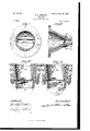
- Figure 1 is a rear view of the intermediate clay-chamber between the machine and the die. said feeding or clay chamber and the die as designed for clays of marked plasticity
- Fig. 3 is a horizontal section or plan view of the same.
- Fig. 4 is a horizontal section of the die when the clay is not so plastic, and a central tongue is extended out from the upper and lower surfaces of the die to retard or hold back the faster-moving central portion of the stream of clay by increasing the friction-surface along this central portion of the stream of clay.
- Fig. 5 is a horizontal section of the die when the clay is still less plastic or when it is desired to work the clay very stiff, and therefore the retarding-tongue is still further lengthened than in Fig. 4, while Fig.
- Fig. 6 is a longitudinal section of the same, showing the devices for varying the friction on the stream of clay and for taking up the wear of Fig. 2 is a longitudinal section through the elongated retarding-tongue.
- Fig. 7 is a rear view
- Fig. Sis a horizontal or sectional plan on the line A B
- Fig. 9 is a longitudinal section on the line C D
- Fig. 10 is another longitudinal section 011 the line E F, of the die when the clay is so plastic that it is only necessary to relieve the friction of the corners of the die by replacing them with the conical enlargements 0 0 to secure a uniform unbroken sheet of clay.
- the die Z) has a larger entrance for the clay stream in the rear at 0 than at the discharge d, so that when the clay is discharged at the mouth of the die at d the narrowing of the cross-section of the die from m m to n n and the consequent contraction in area of the clay stream equalizes the friction when the clay is freely plastic, so that it leaves the die in a uniform unbroken sheet.
- the rate of contraction from m m to a n or the decrease in the cross-section of the die will vary with the plasticity and temper of the clay to be worked.
- the die I has the lower and upper faces prolonged into a tonguef, that should preferably terminate in a parabolic periphery, and the central portion of the clay sheet has to pass between these two tongues after it has passed beyond the corners of the die at n 'n, so that the increased friction caused by these tongues equalizes the greater friction caused by the sides of the die when the clay is rather stiff, or not very plastic.
- the tongues ff are made still longer, as in Fig. 5, to still further increase the friction of the central portion of the clay sheet.
- regulating-screws of which as many can be used as found necessary, also permit the tongues to be made of sheet metal or thin lining material, as they prevent any springing or variation in the gage of the sheet of clay between the tongues, and thus enable the die to be cheaply made and easily and quickly repaired.
- the die I) can be lined with liners c to take up the wear of the die and also enable it to be easily and cheaply repaired or restored to gage as it Wears from use.
- the feeding-chamber a, between the die Z) and the clay-machine may be made of any suitable size or shape to fit the delivery of the clay-machine, the plasticity of the clay, and the size of the die to be used. It is preferably divided into halves, or two pieces, for convenience, and by lugs or flanges itis bolted onto the clay-machine and has lugs or flanges for permitting the die to be bolted or screwed or keyed onto it.
- the die I) is shown solid or in one piece; but it can also be divided into halves or two pieces, which enables the wear to be easily taken up if it is not lined with removable liners.
- the die can also be cored out or bored out with chambers or passages for steam-jacketing to still further decrease the risk of rag ging or breaking of the sheet of clay in pass ing through the die.
- the die can be made with the contraction from c to cl, with the corners re lieved by the large conical enlargements 0'0, and with the retardingsurfaces to the fastermoving central portion of the clay sheet extended as in Figs. 5 and 6, and having the adjusting-screws h h for regulating these retarding-tongues and taking up their wear. If there is not so much variation as to require these three methods jointly, two of them may be used, as found desirable for the clay, as all such mechanical devices should be modi fied to suit the peculiarities of each individual clay.
- An improved die having its upper and lower surfaces extended to form a pair of retarding-surfaces, with adj Listing-screws to regulate said extended retarding-surfaces, with lock-nuts to hold said adj Listing-screws, with arms to carry said adj usting-screws and lock-nuts, substantially as shown.
- An improved die with a contracted discharge, with the upper and lower surfaces extended beyond said contracted discharge to form a pair of retarding-surfaces, with a pair of adjusting-screws to regulate said retarding-surfaces,with lock-nuts to control said adjusting-screws, with arms to carry said adj usting-screws and nuts, substantially as shown and described.
Landscapes
- Engineering & Computer Science (AREA)
- Manufacturing & Machinery (AREA)
- Mechanical Engineering (AREA)
- Press-Shaping Or Shaping Using Conveyers (AREA)
Description
(No Model.)
Patented Dec. 20, I898.
H. A. WHEELER.
TILE DIE.
(Application filed June 20, 1898.)
' -2 Sheets-S'hegt.l.
mm! I No. 6l6,|70. Patented Dec. 20, I898. H. A. WHEELER.
TILE DIE.
(Application filed June 20, 1898.] (No Model.) 2 Sheets-Sheet 2.
NITED STATES PATENT OFFICE.
HERBERT ALLEN WHEELER, OF sr. LOUIS, MISSOURI.
TILE-DIE.-
SFECIFICATION forming part of Letters Patent No. 616,170, dated December 2c, 1898.
Application filed 3' 1111s 20,1898. Serial No. 684,020. (No model.)
To all whom it may concern:
Be it known that I, HERBERT ALLEN WHEELER, a citizen of the United States, residing at the city of St. Louis, in the State of Missouri, have invented certain new and useful improvements in dies for making clay shingles, tiles, blocks, and similar clay products of a sheet-like nature, of which the following is a full, clear, and exact description, such as will enable others skilled in the art to which it appertains to make and use the same.
My invention is an improvement in the die or mold for making uniform, homogeneous, unbroken sheets of clay for roofing-tiles, flooring-tiles, slabs, blocks, and similar products of a sheet-like nature; and it consists of the novel arrangements and combinations hereinafter set forth in the following specification and claims and illustrated by the accompanying drawings.
The die can be adapted to any of the usual designs of clay-working machinery that can form a stream of clay, as an auger-machine, plunger-machine, steam-press, or other devices that can force a sheet of plastic or tempered clay through a die. When such a stream of plastic clay is forced through an ordinary thin die or narrow slot, there is a strong tendency for the resulting sheet of clay to rag or tear on the edges from the differential speeds in the different parts of the sheet of clay in consequence of the variation in the friction, as the central portion moves faster than the sides of the clay in the usual forms of dies.
This ragging or tearing or breaking of the continuity of the edges of the sheet is a grave defect, and my device is to not only overcome this evil, but also accomplish it in such a practical way as to reduce the cost of renewal and repairs incident tothe use of the dies to a minimum by having the wearing parts easily accessible or on the outside of the machine and so designed as to be easily renewed.
As clays differ radically in their nature and physical character, which requires marked variations in their individual methods of manipulation, and as the same clay behaves very differently according as it is either freshly mined or weathered, which latter process renders it much more plastic, and also whether it is tempered soft or stiff, my improvements take cognizance of these variations, and my devices can be varied to meet the peculiarities of each kind of clay in its toughness and plasticity, as well as in the variations in the temper of the same clay, for as these properties of a clay vary the friction of the clay particles among themselves and in passing through the die will vary, and consequently call for variation in the devices for equalizing these differential frictions in order to produce a uniform, homogeneous, unbroken sheet of clay for subsequent use for roofing-tile, fiooringtile, kiln-tile, 01 other purposes.
WVith this object in view my invention consists of equalizing devices to produce uniform friction as the sheet of clay passes through the die or else adding variable friction-surfaces to' such parts of the sheet of clay that tend to fiow too fast or else relieving or easing upon such parts of the clay sheet that tend to flow too slow, according as the character and temper of the clay render either of these methods preferable, or using two or more of these methods in conjunction to secure a uniform unbroken sheet of clay.
lVith these objects in view my invention consists of the following devices, hereinafter described in detail and specifically set forth in the following specification and claims.
In the accompanying drawings similar letters refer to similar parts.
Figure 1 is a rear view of the intermediate clay-chamber between the machine and the die. said feeding or clay chamber and the die as designed for clays of marked plasticity, and Fig. 3 is a horizontal section or plan view of the same. Fig. 4 is a horizontal section of the die when the clay is not so plastic, and a central tongue is extended out from the upper and lower surfaces of the die to retard or hold back the faster-moving central portion of the stream of clay by increasing the friction-surface along this central portion of the stream of clay. Fig. 5 is a horizontal section of the die when the clay is still less plastic or when it is desired to work the clay very stiff, and therefore the retarding-tongue is still further lengthened than in Fig. 4, while Fig. 6 is a longitudinal section of the same, showing the devices for varying the friction on the stream of clay and for taking up the wear of Fig. 2 is a longitudinal section through the elongated retarding-tongue. Fig. 7 is a rear view, Fig. Sis a horizontal or sectional plan on the line A B, Fig. 9 is a longitudinal section on the line C D, and Fig. 10 is another longitudinal section 011 the line E F, of the die when the clay is so plastic that it is only necessary to relieve the friction of the corners of the die by replacing them with the conical enlargements 0 0 to secure a uniform unbroken sheet of clay.
In Figs. 2 and 3 the die Z) has a larger entrance for the clay stream in the rear at 0 than at the discharge d, so that when the clay is discharged at the mouth of the die at d the narrowing of the cross-section of the die from m m to n n and the consequent contraction in area of the clay stream equalizes the friction when the clay is freely plastic, so that it leaves the die in a uniform unbroken sheet. The rate of contraction from m m to a n or the decrease in the cross-section of the die will vary with the plasticity and temper of the clay to be worked.
In Fig. t the die I) has the lower and upper faces prolonged into a tonguef, that should preferably terminate in a parabolic periphery, and the central portion of the clay sheet has to pass between these two tongues after it has passed beyond the corners of the die at n 'n, so that the increased friction caused by these tongues equalizes the greater friction caused by the sides of the die when the clay is rather stiff, or not very plastic. When the clay is more stiff, or still less plastic, the tongues ff are made still longer, as in Fig. 5, to still further increase the friction of the central portion of the clay sheet. As these long tongues are exposed to considerable wear and as they are liable to spring, and hence not press firmly on the sheet of clay, special arms g g are attached to the die by lugs, bolts, screws, or other suitable devices, and from the outer ends of these arms regulating-screws h 7i can be screwed against the outer ends of these tongues to make them retain their gage to prevent them from springing and to take up their wear from use. Locknuts 11 t' and jj on each side of the screws h it hold the latter to their proper places and also enable the screws to be set so as to press more strongly onto the sheet of clay by screwing these regulating-screws against the tongues. These regulating-screws, of which as many can be used as found necessary, also permit the tongues to be made of sheet metal or thin lining material, as they prevent any springing or variation in the gage of the sheet of clay between the tongues, and thus enable the die to be cheaply made and easily and quickly repaired.
When the clay is very plastic, so that there is not much friction in its passage through the die, the slightly-greater friction of the clay in passing through the corners of the die or m it in it than along the central portion of the die is compensated by easing up or enlarging the openings at the rear corners of the die by the conical enlargements o o, as shown in Figs. 7, 8, 9, and 10, as this enlargement reduces and relieves the excessive friction of the corners.
The die I) can be lined with liners c to take up the wear of the die and also enable it to be easily and cheaply repaired or restored to gage as it Wears from use.
The feeding-chamber a, between the die Z) and the clay-machine, may be made of any suitable size or shape to fit the delivery of the clay-machine, the plasticity of the clay, and the size of the die to be used. It is preferably divided into halves, or two pieces, for convenience, and by lugs or flanges itis bolted onto the clay-machine and has lugs or flanges for permitting the die to be bolted or screwed or keyed onto it.
The die I) is shown solid or in one piece; but it can also be divided into halves or two pieces, which enables the wear to be easily taken up if it is not lined with removable liners. The die can also be cored out or bored out with chambers or passages for steam-jacketing to still further decrease the risk of rag ging or breaking of the sheet of clay in pass ing through the die.
\Vhere different kinds of clay are used, or where difierent degrees of tempering of the same clay are worked, or where the least trouble in overcoming the tendency to ragging is desired, the die can be made with the contraction from c to cl, with the corners re lieved by the large conical enlargements 0'0, and with the retardingsurfaces to the fastermoving central portion of the clay sheet extended as in Figs. 5 and 6, and having the adjusting-screws h h for regulating these retarding-tongues and taking up their wear. If there is not so much variation as to require these three methods jointly, two of them may be used, as found desirable for the clay, as all such mechanical devices should be modi fied to suit the peculiarities of each individual clay.
Having thus described my invention, what I claim, and desire to secure by Letters Patcut, is
1. An improved die, having its upper and lower surfaces extended to form a pair of retarding-surfaces, with adj Listing-screws to regulate said extended retarding-surfaces, with lock-nuts to hold said adj Listing-screws, with arms to carry said adj usting-screws and lock-nuts, substantially as shown.
2. An improved die with a contracted discharge, with the upper and lower surfaces extended beyond said contracted discharge to form a pair of retarding-surfaces, with a pair of adjusting-screws to regulate said retarding-surfaces,with lock-nuts to control said adjusting-screws, with arms to carry said adj usting-screws and nuts, substantially as shown and described.
The combination, in an improved die, of
IIO
a pair of arms carrying adjusting-screws,with lock-nuts to control said adj listing-screws, with extended retarding-surfaces from the upper and lower surfaces of said die that are regulated by said adj listing-screws, with said die having a contracted discharge, with the corners in the rear of said die enlarged into conical, converging surfaces, substantially as shown and described.
HERBERT ALLEN WHEELER.
Witnesses:
WM. H. SCOTT, RALPH KALISH.
Publications (1)
| Publication Number | Publication Date |
|---|---|
| US616170A true US616170A (en) | 1898-12-20 |
Family
ID=2684778
Family Applications (1)
| Application Number | Title | Priority Date | Filing Date |
|---|---|---|---|
| US616170D Expired - Lifetime US616170A (en) | Tile-die |
Country Status (1)
| Country | Link |
|---|---|
| US (1) | US616170A (en) |
Cited By (1)
| Publication number | Priority date | Publication date | Assignee | Title |
|---|---|---|---|---|
| US2715256A (en) * | 1952-03-19 | 1955-08-16 | Erie Resistor Corp | Apparatus for making thin ceramic plates |
-
0
- US US616170D patent/US616170A/en not_active Expired - Lifetime
Cited By (1)
| Publication number | Priority date | Publication date | Assignee | Title |
|---|---|---|---|---|
| US2715256A (en) * | 1952-03-19 | 1955-08-16 | Erie Resistor Corp | Apparatus for making thin ceramic plates |
Similar Documents
| Publication | Publication Date | Title |
|---|---|---|
| US616170A (en) | Tile-die | |
| US677200A (en) | Die for brick-machines. | |
| US832725A (en) | Roll. | |
| US1160964A (en) | Beating-engine. | |
| US409309A (en) | Die-bearing disk | |
| US296477A (en) | Assigjtoe of one-half to | |
| US1234017A (en) | Former or die for making hollow tiles. | |
| USD32780S (en) | Design for a butter or oleomargarin print or brick | |
| US109034A (en) | Improvement in brick-machines | |
| US101984A (en) | John g | |
| US607787A (en) | Mold for brick-machines | |
| US627558A (en) | Drawing-die mechanism. | |
| US868866A (en) | Plunger for tile-machines. | |
| US685415A (en) | Machine for making cigars. | |
| US64223A (en) | Improved die fob brick and tile machines | |
| USD28010S (en) | Design for a prism-plate | |
| US720973A (en) | Brick-column die. | |
| US4755A (en) | Jesse fitzgerald | |
| US585407A (en) | Rolls | |
| US735355A (en) | Potter's wheel. | |
| US1509005A (en) | Crushing rolls | |
| USD36646S (en) | Design for a facing-tile | |
| US1301095A (en) | Dies. | |
| US606608A (en) | Rolls | |
| US66536A (en) | Improved machine for gbinding clat |