US6166800A - Solid-state image capture system including H-PDLC color separation element - Google Patents
Solid-state image capture system including H-PDLC color separation element Download PDFInfo
- Publication number
- US6166800A US6166800A US09/221,995 US22199598A US6166800A US 6166800 A US6166800 A US 6166800A US 22199598 A US22199598 A US 22199598A US 6166800 A US6166800 A US 6166800A
- Authority
- US
- United States
- Prior art keywords
- color separation
- light
- voltage
- intrinsic
- liquid crystal
- Prior art date
- Legal status (The legal status is an assumption and is not a legal conclusion. Google has not performed a legal analysis and makes no representation as to the accuracy of the status listed.)
- Expired - Lifetime
Links
Images


Classifications
-
- G—PHYSICS
- G02—OPTICS
- G02B—OPTICAL ELEMENTS, SYSTEMS OR APPARATUS
- G02B5/00—Optical elements other than lenses
- G02B5/20—Filters
- G02B5/201—Filters in the form of arrays
-
- H—ELECTRICITY
- H04—ELECTRIC COMMUNICATION TECHNIQUE
- H04N—PICTORIAL COMMUNICATION, e.g. TELEVISION
- H04N1/00—Scanning, transmission or reproduction of documents or the like, e.g. facsimile transmission; Details thereof
- H04N1/46—Colour picture communication systems
- H04N1/48—Picture signal generators
- H04N1/482—Picture signal generators using the same detector device sequentially for different colour components
-
- H—ELECTRICITY
- H04—ELECTRIC COMMUNICATION TECHNIQUE
- H04N—PICTORIAL COMMUNICATION, e.g. TELEVISION
- H04N25/00—Circuitry of solid-state image sensors [SSIS]; Control thereof
- H04N25/10—Circuitry of solid-state image sensors [SSIS]; Control thereof for transforming different wavelengths into image signals
- H04N25/11—Arrangement of colour filter arrays [CFA]; Filter mosaics
- H04N25/13—Arrangement of colour filter arrays [CFA]; Filter mosaics characterised by the spectral characteristics of the filter elements
- H04N25/135—Arrangement of colour filter arrays [CFA]; Filter mosaics characterised by the spectral characteristics of the filter elements based on four or more different wavelength filter elements
- H04N25/136—Arrangement of colour filter arrays [CFA]; Filter mosaics characterised by the spectral characteristics of the filter elements based on four or more different wavelength filter elements using complementary colours
-
- H—ELECTRICITY
- H04—ELECTRIC COMMUNICATION TECHNIQUE
- H04N—PICTORIAL COMMUNICATION, e.g. TELEVISION
- H04N25/00—Circuitry of solid-state image sensors [SSIS]; Control thereof
- H04N25/10—Circuitry of solid-state image sensors [SSIS]; Control thereof for transforming different wavelengths into image signals
- H04N25/17—Colour separation based on photon absorption depth, e.g. full colour resolution obtained simultaneously at each pixel location
-
- H—ELECTRICITY
- H04—ELECTRIC COMMUNICATION TECHNIQUE
- H04N—PICTORIAL COMMUNICATION, e.g. TELEVISION
- H04N2209/00—Details of colour television systems
- H04N2209/04—Picture signal generators
- H04N2209/041—Picture signal generators using solid-state devices
- H04N2209/042—Picture signal generators using solid-state devices having a single pick-up sensor
- H04N2209/043—Picture signal generators using solid-state devices having a single pick-up sensor using an alternating colour separation filter, e.g. colour wheel or colour LCD
Definitions
- This invention is directed to the field of image capture systems. More particularly, this invention is directed to a solid-state image capture system that includes a holographic polymer dispersed liquid crystal color separation element that can be operated in either a light reflective mode or a transmissive mode to provide fill-color images.
- CMOS complementary metal oxide semiconductor
- the consumer market for image capture systems is already large and is rapidly growing. This is partially fueled by the Internet and World Wide Web, but is also strongly driven by the allure of digital photography and the availability of low-cost, high-quality color printers capable of rendering photographic quality images.
- the market for digital camera systems is expected to reach several billion dollars within the next few years and is, of course, highly competitive and cost sensitive.
- a digital camera system designed to capture images at a sampling density of 1024 ⁇ 768 pixels will typically contain a single image sensor array of 1024 ⁇ 768 sensors with a patterned overlay of red, green and blue color separation filters. From the single signal generated at each sensor location, three, 8-bit color signals for each of the 1024 ⁇ 768 sensor locations must be "reconstructed” or derived to provide a full-color image at the resolution of the sensor. This 1024 ⁇ 768 ⁇ 24-bit image is then stored in the camera (usually in compressed form) and subsequently transferred to a computer system for imaging on a display or for printing on a color printer.
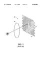
- FIG. 1 schematically illustrates an example of this most common configuration of color image capture system 20 in a color digital camera, a single-path sensor system.
- the image capture system 20 includes a lens 22 and a two-dimensional sensor array (e.g., charge coupled device array) with an integral Beyer color filter (red-green-green-blue) pattern 24 having a redundant green element 26.
- This particular color filter pattern is commonly used in charge coupled device-based color video cameras.
- the higher density of green-filtered sensors enhances the effectiveness of estimating the spatial luminance pattern.
- the class of methods for reconstructing the three, 8-bit color signals at each pixel location are known as "de-mosaicing operations" and are most commonly based upon linear interpolation and block replication procedures. Methods of feature estimation via templates have also been used.
- FIG. 2 illustrates a second known approach to color separation for digital cameras, a three-path sensor system.
- the color separation system 30 includes prism optics and dichroic elements 32 to separate incoming light into three different broad spectral regions C 1 , C 2 and C 3 , which are then imaged on three separate image sensor arrays, 34, 36 and 38, respectively.
- this approach preserves color image integrity and eliminates the need for de-mosaicing and its associated system overhead.
- This approach is typified by the Minolta RD-175 digital camera.
- the three-path sensor system as illustrated in FIG. 2, also has disadvantages.
- the three-path sensor system 30 is more costly than the single-path sensor system due to the need for three image sensors 34, 36 and 38, as well as the prism optics and dichroic elements 32 required to produce the three separate color channels C 1 , C 2 and C 3 .
- the three-path approach and its associated components result in relatively large camera systems with an undesirable form factor. These camera systems tend to be much larger and bulkier than the single-lens reflex camera bodies on which they are based.
- Another disadvantage of known three-path color camera systems is relatively poor color separation due to the use of dichroic elements which pass broad spectral regions either above or below a specific spectral cutoff point. These systems are also prone to passing non-visible wavelengths to the sensor array, which limits the performance of the system in the visible portion of the spectrum.
- the concept of a field-sequential ⁇ cell color shutter for color separation also suffers from a number of disadvantages.
- the color separation performance is limited by the dichroic dyes used in color polarizers and is not easily tunable for particular image sensors.
- the light throughput efficiency is relatively low.
- FIG. 3 shows the measured spectral transmission of a typical ⁇ cell color shutter proposed for use in digital cameras.
- ⁇ cells require a bias voltage be applied to, and maintained on, each liquid crystal cell to maintain the alignment of the liquid crystal molecules in the ⁇ configuration. Moreover, after application of the bias voltage, the liquid crystal molecules may take several seconds to align into a stable ⁇ cell configuration.
- This invention provides an image capture system that includes a liquid crystal color separation element that can be operated in either a light reflective (mirror) mode, or a light transmissive (filter) mode to provide high-quality, full-color and high-resolution monochrome images.
- a liquid crystal color separation element that can be operated in either a light reflective (mirror) mode, or a light transmissive (filter) mode to provide high-quality, full-color and high-resolution monochrome images.
- This invention separately provides an image capture system that includes a holographic polymer dispersed liquid crystal (H-PDLC) color separation element that can achieve full-color images based on either the additive or subtractive primary colors.
- H-PDLC holographic polymer dispersed liquid crystal
- This invention separately provides an image capture system that includes a holographic polymer dispersed cholesteric liquid crystal light separation medium that can achieve full-color images.
- This invention separately provides an image capture system that can include only a single image sensor.
- the color separation element of this invention can achieve color separation of incident light by the use of temporal switching in either the reflective or transmissive modes to sequentially image color components onto only a single image sensor.
- An image capture system comprises a lens, a color separation element and an image sensor.
- the image sensor can be an image sensor array.
- the color separation element receives incident light that is focused by the lens.
- the color separation element includes at least one pair of substrates and a color separation medium between each of the pairs of substrates.
- the color separation medium can comprise a holographic polymer dispersed liquid crystal material.
- the holographic polymer dispersed liquid crystal color separation mediums each reflect light of a selected intrinsic color of the incident light and simultaneously transmit light of substantially all intrinsic colors of the incident light exclusive of the reflected intrinsic color.
- the image sensor is selectively positionable relative to the color separation element to sense either the light that is reflected in the reflective (mirror) mode, or the light that is transmitted in the transmissive (filter) mode, by the holographic polymer dispersed liquid crystal color separation mediums.
- the image capture system can comprise a plurality of pairs of substrates and associated holographic polymer dispersed liquid crystal color separation mediums formed between the respective pairs of substrates.
- the image capture system typically comprises three holographic polymer dispersed liquid crystal color separation mediums that can reflect red, green and blue light, respectively, to provide full-color images.
- the color separation element can comprise a voltage source associated with each pair of substrates and holographic polymer dispersed liquid crystal color separation medium, together forming a cell.
- the holographic polymer dispersed liquid crystal color separation mediums reflect light of a selected intrinsic color in the field-off state, and transmit substantially all colors when the applied voltage is above a threshold voltage. Accordingly, by selectively and independently applying voltage to different cells, the non-powered cells can reflect light of selected intrinsic colors, and the powered cells can transmit all other intrinsic colors.
- the reflected colors can be combined additively and the transmitted colors can be combined by subtractive color mixing, to achieve full-color images in reflective or transmissive operational modes.
- the image capture system can comprise a first image sensor to sense the intrinsic colors that are reflected by the color separation element, and a second image sensor to sense the transmitted subtractive primary colors, so that the image capture system can be operated selectively in either the reflective mode or the transmissive mode.
- This invention also provides methods of separating intrinsic colors of light.
- FIG. 1 schematically illustrates a conventional image capture system that includes a single filtered sensor array
- FIG. 2 schematically illustrates another conventional image capture system that includes prism optics, dichroic elements and three separate image sensor arrays;
- FIG. 3 shows the measured spectral transmission of a ⁇ cell color shutter
- FIG. 4 illustrates an exemplary image capture system according to this invention, which comprises a holographic polymer dispersed liquid crystal (H-PDLC) color separation element that functions as a color separation mirror;
- H-PDLC holographic polymer dispersed liquid crystal
- FIG. 5 illustrates an exemplary embodiment of a color separation element including holographic polymer dispersed liquid crystal color separation mediums for use in the image capture system of FIG. 4;
- FIG. 6 illustrates one possible set of spectral reflectance functions (i.e., spectral reflectance versus light wavelength) of a holographic polymer dispersed liquid crystal separation element of the image capture system of FIG. 4;
- FIG. 7 illustrates another exemplary image capture system according to this invention, which comprises a holographic polymer dispersed liquid crystal color separation element that functions as a color separation filter;
- FIG. 8 illustrates one possible set of spectral transmission functions (i.e., spectral transmission versus light wavelength) of a holographic polymer dispersed liquid crystal color separation element of the image capture system of FIG. 7.
- FIG. 4 shows an exemplary image capture system 40 according to this invention.
- the image capture system 40 can be a full-color image capture system such as a digital camera and can capture still and/or moving images.
- the image capture system 40 comprises a lens 42, a color separation element 44, and an image sensor array 45.
- the lens 42 focuses and directs light L onto the color separation element 44.
- the color separation element 44 operates in the reflective mode as a color separation mirror.
- the light that is reflected by the color separation element 44 is directed onto an image sensor such as the image sensor array 45.
- the lens 42 can be any suitable single lens or a lens system for focusing the incident light L onto the color separation element 44.
- the image sensor array 45 can be, for example, an ordered array of complementary metal oxide silicon (CMOS) devices or a charge coupled devices (CCD). Any other known or later developed image sensor technology can also be used in the image capture system 40.
- CMOS complementary metal oxide silicon
- CCD charge coupled devices
- Any other known or later developed image sensor technology can also be used in the image capture system 40.
- the image sensor array 45 comprises a uniform array of monochrome sensors and can provide a substantially higher spatial resolving capacity than image sensors of comparable device density having patterned filter arrays, such as the image sensor 24 shown in FIG. 1.
- the color separation element 44 comprises three cells 46, 48 and 50.
- the cells 46, 48 and 50 each include a pair of opposed substrates 52 whose base material may be any transparent medium such as glass or plastic, which are each coated with an electrically conductive, optically transparent material, such as indium tin oxide (ITO), and also a voltage source 54, 56 and 58, respectively, electrically connected to the pairs of substrates 52.
- the cells 46, 48 and 50 include color separation mediums 60, 62 and 64, respectively.
- the color separation element 44 can also include a black absorbing material 66 at a rear end to absorb non-reflected light wavelengths.
- the color separation mediums 60, 62 and 64 of the respective cells 46, 48 and 50 can comprise holographic polymer dispersed liquid crystal (H-PDLC) materials. These materials exhibit high-efficiency Bragg reflection at selected wavelengths and, thus, at selected intrinsic colors.
- Holographic polymer dispersed liquid crystal mediums are fabricated by exposing a mixture of liquid crystal and polymer materials to an optical standing wave pattern created by interfering coherent light beams. The standing wave pattern causes the phase separation of the liquid crystal and polymer materials in the mixture, creating a stratified structure including alternating polymer-rich and liquid-crystal-rich layers. Once the phase separation of the mixture into the layered structure is completed, the stratified structure can be "locked in” by curing with ultraviolet radiation.
- the periodic structure that is created exhibits alternating layers of different refractive indices in the field-off state, in which no voltage is applied to the color separation medium.
- the different refractive indices of the layers cause constructive interference and high-efficiency Bragg reflection centered about the desired Bragg wavelength.
- the Bragg wavelengths of the polymer/liquid crystal mixtures that form the color separation mediums 60, 62 and 64 can be varied by selecting the wavelengths and/or incident angles of the light beams that irradiate the mixtures.
- two laser beams are used to fabricate the multi-layer structure in polymer/liquid crystal mixtures.
- the reflected (Bragg) wavelength is changed by controlling the period of the refractive index modulation.
- the holographic polymer dispersed liquid crystal materials that comprise the color separation mediums 60, 62 and 64 can be formed to include groups of alternating liquid-crystal-rich and polymer-rich layers, with each group of layers being reflective of a different wavelength of light.
- These holographic structures can reflect multiple, closely spaced wavelengths of a selected color as represented by separate reflectance sub-peaks, each having a separate spectral bandwidth. These sub-peaks together relate to spectral peaks having broader bandwidths.
- the cells 46, 48 and 50 can include holographic polymer dispersed liquid crystal color separation mediums 60, 62 and 64, respectively, that are each reflective of light of a different intrinsic color R 1 , R 2 and R 3 , respectively, in the field-off state.
- the field-off state no voltage is applied across the cells 46, 48 and 50 by the voltage sources 54, 56 and 58.
- the refractive index of the liquid crystal material n LC is different from the refractive index of the polymer n p .
- Light of a finite spectral bandwidth centered about the Bragg wavelength is thus reflected from the holographic polymer dispersed liquid crystal mediums.
- the color separation element 44 can be formed to reflect the additive primary colors red, green and blue.
- the color separation medium 60 can be formed to reflect blue light
- the color separation medium 62 can be formed to reflect green light
- the color separation medium 64 can be formed to reflect red light in the field-off state. Accordingly, in the field-off state, the color separation element 44 can reflect blue, green and red light.
- the reflected colors can be mixed according to the rule of additive color mixing to achieve all colors.
- Another advantage of this invention is that the reflection direction of the holographically formed color separation mediums 60, 62 and 64 can be made to be away from the surface reflection of the color separation element 44. This can be achieved by setting the two interfering laser beams at appropriate angles so that the interfering fringe layer are tilting away from the substrates 52. This will separate the surface reflection or glare component of the reflected light away from the reflected light of the different intrinsic colors R 1 , R 2 and R 3 .
- the reflected intrinsic colors R 1 , R 2 and R 3 are directed to the image sensor array 45 and the glare component is directed out of the image path to a light trap.
- the effective removal of the glare component from the reflected light L R path achieves better color separation and improves the sensitivity of the image capture system 40 by keeping uncontrolled and unmodulated light from going into the image sensor array 45.
- FIG. 6 shows a plot of the modeled spectral reflectance versus wavelength for the color separation element 44 in which the color separation mediums 60, 62 and 64 reflect closely spaced wavelengths of blue (B), green (G) and red (R) light, respectively.
- This plot is exemplary of only one of an infinite variety of spectral reflectance functions achievable with the holographic polymer dispersed liquid crystal color separation element 44.
- the peaks B, G and R each include separate reflectance sub-peaks each having a separate bandwidth.
- the blue peak B includes the sub-peaks B 1 , B 2 and B 3 ;
- the green peak G includes the sub-peaks G 1 , G 2 and G 3 ;
- the peak R includes the sub-peaks R 1 , R 2 and R 3 .
- the color separation mediums 60, 62 and 64 can be formed to reflect respective different intrinsic colors having single reflectance peaks B, G, R, a different number of sub-peaks, or some other combination of intrinsic colors.
- the voltage sources 54, 56 and 58 can selectively apply a voltage to the holographic polymer dispersed liquid crystal color separation mediums 60, 62 and 64, respectively, to cause the holographic polymer dispersed liquid crystal material to transmit light that was formerly reflected in the field-off state.
- a certain threshold voltage level is applied, re-orientation of the liquid crystal molecules causes the refractive index n LC of the liquid crystal material to become approximately equal to the refractive index n p of the polymer material, and the periodic refractive index modulation of the holographic polymer dispersed liquid crystal material is effectively removed.
- the different cells 46, 48 and 50 of the color separation element can each have a different threshold voltage at which the cells display complete light transmission.
- the color separation element 44 can operate in a reverse manner by the use of so-called negative liquid crystal materials; i.e., the holographic polymer dispersed liquid crystal color separation mediums can transmit light in the field-off state and reflect light in the field-on state.
- a voltage can be selectively and independently applied to the color separation mediums 60, 62 and 64 by the respective voltage sources 54, 56 and 58, to cause the color separation mediums to selectively reflect or transmit light.
- the color separation mediums 60, 62 and 64 when no voltage is applied to one or more of the color separation mediums 60, 62 and 64, then light at and about the associated Bragg wavelengths is reflected from the color separation mediums to which no voltage is applied.
- a threshold voltage can be applied to one or more of the color separation mediums 60, 62 and 64 to cause those mediums to transmit the incident light.
- a voltage can be applied to the color separation mediums 62 and 64 by the voltage sources 56 and 58 while no voltage is applied to the color separation medium 60, so that the cell 46 reflects light of the associated Bragg wavelength of the color separation medium 60, and the cells 48 and 50 transmit intrinsic colors that are not reflected by the color separation medium 60.
- the color separation element 44 of the image capture system 40 operates in the reflective mode as a color separation mirror.
- Light L that is incident on the lens 42 is focused by the lens 42 onto the color separation element 44.
- the color separation element 44 can selectively reflect light of one, two or three different intrinsic colors from the cells 46, 48 and 50.
- the light L R that is reflected by the color separation element 44 is directed to the image sensor array 45.
- the image sensor array 45 can comprise a sensor array as schematically shown in FIG. 4.
- the color separation element 44 is operated to separately reflect light of each of the three intrinsic colors that it can reflect onto the image sensor array 45, each for a predetermined amount of time in order to capture a full-color image. That is, the color separation element can be operated such that the cell 46 is in the field-off state and the cells 48 and 50 are each in the field-on state, so that blue light is reflected onto the image sensor array 45 for a predetermined amount of time in order to capture a blue portion of the full-color image.
- the cell 48 can be in the field-off state while the cells 46 and 50 are each in the field-on state, so that the color separation element 44 reflects green light onto the image sensor array 45 for a predetermined amount of time in order to capture a green portion of the full-color image.
- the color separation element 44 can be operated such that the cell 50 is in the field-off state and the cells 46 and 48 are each in the field-on state, so that red light is reflected onto the image sensor array 45 for a predetermined amount of time in order to capture a red portion of the full-color image.
- the image capture system 40 can be operated in different selected color reflection sequences. The color reflection sequence that is followed can be varied to reflect the colors in any selected order or pattern, and for any predetermined amount of time for each of the different colors.
- a highly efficient and selective color separation element 44 that functions as a color separation mirror can be provided to enable independent control of the spectral reflectance bands from each of the cells 46, 48 and 50.
- High-resolution monochrome images can be acquired by operating the color separation element 44 in the following manner: Each of the cells 46, 48 and 50 are operated in the field-off state simultaneously for a predetermined amount of time. This results in the color separation element 44 reflecting light of each of the three intrinsic colors to the image sensor array 45 simultaneously so as to acquire an accurate, photopically-weighted monochrome image.
- FIG. 6 which illustrates the transmission versus wavelength performance for a ⁇ cell color shutter system
- the image capture system 40 can achieve relatively better light transmission throughput and more accurate spectral control than ⁇ cell color shutter systems. Accordingly, the image capture system 40 can achieve better images under low light level conditions.
- the image capture system 40 can substantially avoid "cross-talk" caused by overlap of adjacent spectral peaks that occur in ⁇ cell color shutter systems, as shown in FIG. 3.
- FIG. 7 illustrates an exemplary image capture system 140 according to this invention that operates in the light transmissive (filter) mode as a color separation filter.
- the image capture system 140 includes a lens or lens system 142 to focus incident light onto the color separation element 144, which transmits light onto an image sensor such as the image sensor array 145.
- the color separation element 144 can have the same configuration as the color separation element 44 shown in FIG. 5.
- a difference between the configuration of the image capture system 140 and the image capture system 40 is the position of the image sensor array 145 relative to the color separation element 144 as compared to the positioning of the image sensor array 45 relative to the color separation element 44.
- the image capture system 140 comprises a straight through optical path.
- This difference in positioning of the image sensor arrays 45 and 145 in the respective image capture systems 40 and 140 is due to the light being reflected from the color separation mediums 60, 62 and 64 and exiting the color separation element 44 via the light inlet surface 68 of the color separation element 44 of the image capture system 40, in contrast to the light being transmitted through the color separation mediums 60, 62 and 64 of the color separation element 144 and emerging from the light outlet surface 148.
- the image sensor arrays 45 and 145 are positioned to receive the reflected and transmitted light, respectively.
- the transmissive mode of the color separation element 144 is achieved when one or more of the cells of the color separation element 144, such as cells 46, 48 and 50 shown in FIG. 5 for the color separation element 40, are selectively operated in the field-on state.
- the applied electric field causes the refractive index n LC of the liquid crystal material to approximately equal the refractive index n p of the polymer material.
- the selected cells of the color separation element 144 that are subjected to an electric field transmit light and no reflection occurs from these cells. Cells of the color separation element 144 that are in the field-off state reflect light, as described above for the color separation element 40.
- Cells that are in the field-on state can transmit light of the colors that are not reflected by the cell in the off-state, such that the color separation element can provide subtractive color separation components of cyan (C), magenta (M) and yellow (Y). These colors are also referred to as the subtractive primary colors.
- one cell of the color separation element 144 can be in the field-off state and accordingly reflect an associated intrinsic color, while two other cells of the color separation element are simultaneously in the field-on state and accordingly transmit two respective different intrinsic colors that are not reflected by the cell in the field-off state.
- red light can be reflected by one cell while blue and green light are transmitted by two other cells of the color separation element 144.
- the transmitted blue and green light will combine to produce the subtractive primary color cyan image at the image sensor array 145.
- blue light can be reflected by one cell while red and green light are transmitted by two other cells.
- the transmitted red and green light will combine to produce the subtractive primary color yellow image at the image sensor array 145.
- green light can be reflected by one cell in the field-off while blue and red light are transmitted by two other cells in the field-on state.
- the transmitted blue and red light will combine to produce the subtractive primary color magenta image at the sensor array 145.
- the color separation element 144 can be operated with two cells in the off-state and one cell in the on-state, so that two different intrinsic colors can be reflected and a third intrinsic color can be transmitted onto the image sensor array 145 for a predetermined amount of time.
- cells of the color separation element 144 that reflect red and blue light can be in the field-off state, so that red and blue are reflected, while a third cell of the color separation element 144 can be in the field-on state so that it transmits a third color such as green.
- Operation of the image capture system 140 in the transmissive mode can be particularly advantageous to transfer images directly to color hardcopy systems.
- the separation into the subtractive primaries cyan, magenta and yellow matches the hardcopy primaries and eliminates the need for transformations from red, green and blue to cyan, magenta and yellow.
- FIG. 8 shows a plot of the modeled spectral transmission versus light wavelength for the color separation element 144 including H-PDLC mediums that can transmit yellow (Y), magenta (M) and cyan (C) images.
- This plot is exemplary of only one of an infinite variety of spectral transmission functions achievable with an H-PDLC color separation element 144.
- each of the transmission curves for the three different colors includes separate transmission sub-troughs, each having a separate bandwidth.
- the yellow curve Y includes the sub-troughs Y 1 , Y 2 and Y 3 ;
- the magenta curve M includes the sub-troughs M 1 , M 2 and M 3 ;
- the cyan curve C includes the sub-troughs C 1 , C 2 and C 3 .
- Each transmission sub-trough represents the light wavelengths removed from the transmission path due to the reflection characteristics of the H-PDLC media.
- the yellow transmission curve Y results from a set of "blue" H-PDLC layers reflecting blue light out of the transmission path; hence the light that is transmitted is deficient in blue light and relatively abundant in green and red light to result in yellow light transmission.
- the fact that there is some blue light (about 20%) left in the resulting transmission spectrum does not degrade image quality because this residual blue light can be accounted for during post image-capture processing.
- the color separation mediums of the color separation element 144 can be formed to transmit different respective colors having single reflectance troughs Y, M, C, a different number of sub-troughs, or some other combination of intrinsic colors.
- the color transmission sequence that is followed using the image capture system 140 can be varied to transmit intrinsic colors in any selected order or pattern, and for any predetermined amount of time.
- high-resolution monochrome images can be acquired by operating the cells of color separation element 144 in the field-on state for a predetermined amount of time. This results in the color separation element 144 transmitting light of all intrinsic colors to the image sensor array 145 simultaneously so as to acquire an accurate, photopically-weighted monochrome image.
- exemplary embodiments of the image capture system can comprise a single color separation element 44, and two separate image sensors, such as the image sensor arrays 45 and 145.
- image capture systems can simultaneously receive the light that is reflected and the light that is transmitted by the color separation element. That is, the light that is reflected by the cells of the color separation element can be directed to one image sensor such as the image sensor array 45 of the image capture system 40. The light that is transmitted by the cells of the color separation element can be directed to a second image sensor aligned with the color separation element as in the image capture system 140.
- Such image capture systems can thus provide the advantages of both the reflective (mirror) mode and the transmissive (filtering) mode in a single image capture system.
- the use of holographic polymer dispersed liquid crystal materials in the cells of the color separation elements 44 and 144 can provide important advantages, but need not necessarily provide any particular advantage, for use in image capture systems 40 and 140 according to this invention.
- the color separation elements can provide highly tunable center wavelengths, spectral bandwidths and peak reflectances and transmissions for each different intrinsic color component.
- the color separation elements can provide a high light throughput efficiency, and can be readily optimized for particular image sensor spectral responses and applications.
- the color separation elements employing holographic polymer dispersed liquid crystal materials are capable of extremely fast switching times between field-off and field-on states, which is particularly advantageous for image capture systems based on field-sequential color separation.
- the color separation element 44 can be operated as a color separation mirror (reflective mode) producing additive red, green and blue color separations, while the color separation element 144 can be operated as a color separation filter (transmissive mode) to produce subtractive cyan, magenta and yellow color separations.
- the reflective mode the front glare can be removed from the image path thereby increasing image quality.
- the image capture systems 40 and 140 can be made to acquire high-resolution, monochrome images as well as color images.
- the image capture systems 40 and 140 comprise respective color separation elements 44 and 144 that can provide field-sequential color separation in combination with a single image sensor array 45 and 145, to form the basis of high-quality image capture systems at relatively low cost compared with other known approaches to color separation.
- the image capture systems 40 and 140 can be used in full-color digital cameras, such as digital still-image and video cameras.
- the image capture system 140 can be used in direct image transfer systems such as full-color hardcopy systems. Further cost reduction for the image capture system 40 may be obtained by taking advantage of the fact that each color separation lies on a slightly different focal plane, thereby allowing the use of inexpensive camera lenses which require little or no correction for axial chromatic aberration.
Landscapes
- Engineering & Computer Science (AREA)
- Multimedia (AREA)
- Signal Processing (AREA)
- Physics & Mathematics (AREA)
- General Physics & Mathematics (AREA)
- Optics & Photonics (AREA)
- Spectroscopy & Molecular Physics (AREA)
- Color Television Image Signal Generators (AREA)
- Diffracting Gratings Or Hologram Optical Elements (AREA)
- Liquid Crystal (AREA)
Priority Applications (3)
| Application Number | Priority Date | Filing Date | Title |
|---|---|---|---|
| US09/221,995 US6166800A (en) | 1998-12-29 | 1998-12-29 | Solid-state image capture system including H-PDLC color separation element |
| IDW20001619A ID26321A (id) | 1998-12-29 | 1999-12-17 | Transmisi ulasan dengan tanda tangan digital |
| JP37210699A JP4527224B2 (ja) | 1998-12-29 | 1999-12-28 | H−pdlc色分解エレメントを含む固体撮像装置およびその製造方法 |
Applications Claiming Priority (1)
| Application Number | Priority Date | Filing Date | Title |
|---|---|---|---|
| US09/221,995 US6166800A (en) | 1998-12-29 | 1998-12-29 | Solid-state image capture system including H-PDLC color separation element |
Publications (1)
| Publication Number | Publication Date |
|---|---|
| US6166800A true US6166800A (en) | 2000-12-26 |
Family
ID=22830297
Family Applications (1)
| Application Number | Title | Priority Date | Filing Date |
|---|---|---|---|
| US09/221,995 Expired - Lifetime US6166800A (en) | 1998-12-29 | 1998-12-29 | Solid-state image capture system including H-PDLC color separation element |
Country Status (3)
| Country | Link |
|---|---|
| US (1) | US6166800A (id) |
| JP (1) | JP4527224B2 (id) |
| ID (1) | ID26321A (id) |
Cited By (17)
| Publication number | Priority date | Publication date | Assignee | Title |
|---|---|---|---|---|
| US6538775B1 (en) * | 1999-09-16 | 2003-03-25 | Reveo, Inc. | Holographically-formed polymer dispersed liquid crystals with multiple gratings |
| US6570633B1 (en) * | 1999-06-21 | 2003-05-27 | Eastman Kodak Company | Multi-layer neutral density sheet having a plurality of light-modulating layers with memory properties |
| US6678078B1 (en) * | 1999-01-07 | 2004-01-13 | Digilens, Inc. | Optical filter employing holographic optical elements and image generating system incorporating the optical filter |
| US6885414B1 (en) * | 2000-09-29 | 2005-04-26 | Kent Optronics, Inc. | Optical router switch array and method for manufacture |
| US20050225656A1 (en) * | 2004-04-07 | 2005-10-13 | Fuji Photo Film Co., Ltd. | Imaging sensor |
| US7209142B1 (en) * | 1999-07-15 | 2007-04-24 | Fujifilm Corporation | Image display method and an image display apparatus for implementing the method |
| US20070216979A1 (en) * | 2006-03-16 | 2007-09-20 | Jabil Circuit, Inc. | Multi-state optical switch and combiner for use in a light engine and image presentation device using the same |
| US20090015767A1 (en) * | 2007-07-03 | 2009-01-15 | Sharp Kabushiki Kaisha | Solid-state image capturing device, manufacturing method for the solid-state image capturing device, color filter and forming method for the color filter, liquid crystal display apparatus, and electronic information device |
| US7570405B1 (en) | 2003-04-08 | 2009-08-04 | Science Applications International Corporation | Optimizing performance parameters for switchable polymer dispersed liquid crystal optical elements |
| US7583423B2 (en) * | 1996-07-12 | 2009-09-01 | Science Applications International Corporation | Switchable polymer-dispersed liquid crystal optical elements |
| US20110149574A1 (en) * | 2009-12-22 | 2011-06-23 | Industrial Technology Research Institute | Illumination system |
| US20110199563A1 (en) * | 2008-10-14 | 2011-08-18 | Drexel University | Polymer Dispersed Liquid Crystal Photovoltaic Device and Method for Making |
| US20120281081A1 (en) * | 2011-05-02 | 2012-11-08 | Sony Corporation | Infrared imaging system and method of operating |
| US20130222739A1 (en) * | 2012-02-29 | 2013-08-29 | Boe Technology Group Co., Ltd. | Transparent display unit |
| US20150234102A1 (en) * | 2012-08-20 | 2015-08-20 | Drexel University | Dynamically focusable multispectral light field imaging |
| US20180024004A1 (en) * | 2010-10-29 | 2018-01-25 | Drexel University | Tunable electro-optic filter stack |
| CN111505890A (zh) * | 2020-04-22 | 2020-08-07 | 四川大学 | 一种2d/3d兼容的前投影显示装置 |
Citations (9)
| Publication number | Priority date | Publication date | Assignee | Title |
|---|---|---|---|---|
| US4596445A (en) * | 1983-03-30 | 1986-06-24 | Manchester R & D Partnership | Colored encapsulated liquid crystal apparatus using enhanced scattering |
| US4952033A (en) * | 1987-07-13 | 1990-08-28 | James L. Fergason | Liquid crystal medical device |
| US5124818A (en) * | 1989-06-07 | 1992-06-23 | In Focus Systems, Inc. | LCD system having improved contrast ratio |
| US5193015A (en) * | 1989-10-05 | 1993-03-09 | Thorn Emi Plc | Cholesteric liquid crystal screen which reflects substantially all of the projected light |
| US5200845A (en) * | 1989-10-31 | 1993-04-06 | University Of Hawaii At Manoa | Color liquid crystal display consisting of polymer-dispersed chiral liquid crystal having negative dielectric anisotropy |
| US5539548A (en) * | 1991-10-08 | 1996-07-23 | Semiconductor Energy Laboratory Co., Ltd. | Electro-optical device with laminated layers of liquid crystal an light scattering support layers |
| US5729320A (en) * | 1990-10-12 | 1998-03-17 | Rudolf Eidenschink | Liquid crystalline medium including closely packed particles and method for generating images using same |
| US5751452A (en) * | 1993-02-22 | 1998-05-12 | Nippon Telegraph And Telephone Corporation | Optical devices with high polymer material and method of forming the same |
| US5875012A (en) * | 1997-01-31 | 1999-02-23 | Xerox Corporation | Broadband reflective display, and methods of forming the same |
Family Cites Families (4)
| Publication number | Priority date | Publication date | Assignee | Title |
|---|---|---|---|---|
| JP3372291B2 (ja) * | 1993-04-30 | 2003-01-27 | 大日本印刷株式会社 | ホログラムを用いた画像読み取り装置 |
| JPH06347643A (ja) * | 1993-06-08 | 1994-12-22 | Matsushita Electric Ind Co Ltd | 色分解光学系および色分解方法 |
| JP3136071B2 (ja) * | 1995-04-14 | 2001-02-19 | シャープ株式会社 | 画像処理装置及び撮像装置 |
| JP3888648B2 (ja) * | 1996-07-26 | 2007-03-07 | 大日本印刷株式会社 | 反射型カラー表示装置 |
-
1998
- 1998-12-29 US US09/221,995 patent/US6166800A/en not_active Expired - Lifetime
-
1999
- 1999-12-17 ID IDW20001619A patent/ID26321A/id unknown
- 1999-12-28 JP JP37210699A patent/JP4527224B2/ja not_active Expired - Fee Related
Patent Citations (9)
| Publication number | Priority date | Publication date | Assignee | Title |
|---|---|---|---|---|
| US4596445A (en) * | 1983-03-30 | 1986-06-24 | Manchester R & D Partnership | Colored encapsulated liquid crystal apparatus using enhanced scattering |
| US4952033A (en) * | 1987-07-13 | 1990-08-28 | James L. Fergason | Liquid crystal medical device |
| US5124818A (en) * | 1989-06-07 | 1992-06-23 | In Focus Systems, Inc. | LCD system having improved contrast ratio |
| US5193015A (en) * | 1989-10-05 | 1993-03-09 | Thorn Emi Plc | Cholesteric liquid crystal screen which reflects substantially all of the projected light |
| US5200845A (en) * | 1989-10-31 | 1993-04-06 | University Of Hawaii At Manoa | Color liquid crystal display consisting of polymer-dispersed chiral liquid crystal having negative dielectric anisotropy |
| US5729320A (en) * | 1990-10-12 | 1998-03-17 | Rudolf Eidenschink | Liquid crystalline medium including closely packed particles and method for generating images using same |
| US5539548A (en) * | 1991-10-08 | 1996-07-23 | Semiconductor Energy Laboratory Co., Ltd. | Electro-optical device with laminated layers of liquid crystal an light scattering support layers |
| US5751452A (en) * | 1993-02-22 | 1998-05-12 | Nippon Telegraph And Telephone Corporation | Optical devices with high polymer material and method of forming the same |
| US5875012A (en) * | 1997-01-31 | 1999-02-23 | Xerox Corporation | Broadband reflective display, and methods of forming the same |
Non-Patent Citations (16)
| Title |
|---|
| Crawford, G.P. et al. Ed., "Liquid Crystals in Complex Geometries: Formed by Polymer and Porous Networks," Taylor & Francis, 1996, pp. 103-142, 255-264 265-280, and 307-324. |
| Crawford, G.P. et al. Ed., Liquid Crystals in Complex Geometries: Formed by Polymer and Porous Networks, Taylor & Francis, 1996, pp. 103 142, 255 264 265 280, and 307 324. * |
| Crawford, G.P. et al., "Reflective Color LCDs Based on H-PDLCand PSCT Technologies," 4 pp. |
| Crawford, G.P. et al., Reflective Color LCDs Based on H PDLCand PSCT Technologies, 4 pp. * |
| Crawford, Gregory P. et al., "Reflective Color Display for Imaging Applications," IS&T/SID 1995 Color Imaging Conference: Color Science, Systems and Applications, pp. 52-58. |
| Crawford, Gregory P. et al., Reflective Color Display for Imaging Applications, IS&T/SID 1995 Color Imaging Conference: Color Science, Systems and Applications, pp. 52 58. * |
| Date, M. et al., S24 2: Three Primary Color Holographic Polymer Dispersed Liquid Crystal (HPDLC) Devices For Reflective Displays, Asia Display 95, pp. 603 606, 1995. * |
| Date, M. et al., S24-2: Three-Primary-Color Holographic Polymer Dispersed Liquid Crystal (HPDLC) Devices For Reflective Displays, Asia Display 95, pp. 603-606, 1995. |
| Kreuzer, M. et al., "New Liquid Crystal Display with Bistability and Selective Erasure Using Scattering in Filled Nematics," Appl. Phys. Lett. 62 (15), 1993, pp. 1712-1714. |
| Kreuzer, M. et al., New Liquid Crystal Display with Bistability and Selective Erasure Using Scattering in Filled Nematics, Appl. Phys. Lett. 62 (15), 1993, pp. 1712 1714. * |
| Tanaka, K. et al., "18.1: Optimization of Holographic PdLC for Reflective Color Display Applications," SID 95 Digest, pp. 267-270, 1995. |
| Tanaka, K. et al., "A Liquid-Crystal/Polymer Optical Device Fotmed by Holography for Reflective Color Display Applications," NTT, Interdisciplinary research Laboratories, pp. 109-111. |
| Tanaka, K. et al., 18.1: Optimization of Holographic PdLC for Reflective Color Display Applications, SID 95 Digest, pp. 267 270, 1995. * |
| Tanaka, K. et al., A Liquid Crystal/Polymer Optical Device Fotmed by Holography for Reflective Color Display Applications, NTT, Interdisciplinary research Laboratories, pp. 109 111. * |
| Tanaka, Keiji et al., "Holographically Formed Liquid-Crystal/Polymer Device for Reflective Color Display," Journal of the SID 2/1, 1994, pp. 37-40. |
| Tanaka, Keiji et al., Holographically Formed Liquid Crystal/Polymer Device for Reflective Color Display, Journal of the SID 2/1, 1994, pp. 37 40. * |
Cited By (28)
| Publication number | Priority date | Publication date | Assignee | Title |
|---|---|---|---|---|
| US7583423B2 (en) * | 1996-07-12 | 2009-09-01 | Science Applications International Corporation | Switchable polymer-dispersed liquid crystal optical elements |
| US6678078B1 (en) * | 1999-01-07 | 2004-01-13 | Digilens, Inc. | Optical filter employing holographic optical elements and image generating system incorporating the optical filter |
| US6570633B1 (en) * | 1999-06-21 | 2003-05-27 | Eastman Kodak Company | Multi-layer neutral density sheet having a plurality of light-modulating layers with memory properties |
| US7209142B1 (en) * | 1999-07-15 | 2007-04-24 | Fujifilm Corporation | Image display method and an image display apparatus for implementing the method |
| US6538775B1 (en) * | 1999-09-16 | 2003-03-25 | Reveo, Inc. | Holographically-formed polymer dispersed liquid crystals with multiple gratings |
| US6885414B1 (en) * | 2000-09-29 | 2005-04-26 | Kent Optronics, Inc. | Optical router switch array and method for manufacture |
| US7570405B1 (en) | 2003-04-08 | 2009-08-04 | Science Applications International Corporation | Optimizing performance parameters for switchable polymer dispersed liquid crystal optical elements |
| US7872707B1 (en) | 2003-04-08 | 2011-01-18 | Science Applications International Corporation | Method for controlling an index modulation of a switchable polymer dispersed liquid crystal optical component |
| US7570322B1 (en) | 2003-04-08 | 2009-08-04 | Science Applications International Corporation | Optimizing performance parameters for switchable polymer dispersed liquid crystal optical elements |
| US7605882B1 (en) | 2003-04-08 | 2009-10-20 | Science Applications International Corporation | Optimizing performance parameters for switchable polymer dispersed liquid crystal optical elements |
| US8077274B2 (en) | 2003-04-08 | 2011-12-13 | Science Applications International Corporation | Optimizing performance parameters for switchable polymer dispersed liquid crystal optical elements |
| US20050225656A1 (en) * | 2004-04-07 | 2005-10-13 | Fuji Photo Film Co., Ltd. | Imaging sensor |
| US20070216979A1 (en) * | 2006-03-16 | 2007-09-20 | Jabil Circuit, Inc. | Multi-state optical switch and combiner for use in a light engine and image presentation device using the same |
| US7570404B2 (en) | 2006-03-16 | 2009-08-04 | Jabil Circuit, Inc. | Multi-state optical switch and combiner for use in a light engine and image presentation device using the same |
| US20090015767A1 (en) * | 2007-07-03 | 2009-01-15 | Sharp Kabushiki Kaisha | Solid-state image capturing device, manufacturing method for the solid-state image capturing device, color filter and forming method for the color filter, liquid crystal display apparatus, and electronic information device |
| US7800716B2 (en) * | 2007-07-03 | 2010-09-21 | Sharp Kabushiki Kaisha | Solid-state image capturing device, manufacturing method for the solid-state image capturing device, color filter and forming method for the color filter, liquid crystal display apparatus, and electronic information device |
| US9140923B2 (en) * | 2008-10-14 | 2015-09-22 | Drexel University | Polymer dispersed liquid crystal photovoltaic device and method for making |
| US20110199563A1 (en) * | 2008-10-14 | 2011-08-18 | Drexel University | Polymer Dispersed Liquid Crystal Photovoltaic Device and Method for Making |
| US20110149574A1 (en) * | 2009-12-22 | 2011-06-23 | Industrial Technology Research Institute | Illumination system |
| US10175106B2 (en) * | 2010-10-29 | 2019-01-08 | Drexel University | Tunable electro-optic filter stack |
| US20180024004A1 (en) * | 2010-10-29 | 2018-01-25 | Drexel University | Tunable electro-optic filter stack |
| US9800804B2 (en) | 2011-05-02 | 2017-10-24 | Sony Corporation | Infrared imaging system and method of operating |
| US9055248B2 (en) * | 2011-05-02 | 2015-06-09 | Sony Corporation | Infrared imaging system and method of operating |
| US20120281081A1 (en) * | 2011-05-02 | 2012-11-08 | Sony Corporation | Infrared imaging system and method of operating |
| US9429787B2 (en) * | 2012-02-29 | 2016-08-30 | Boe Technology Group Co., Ltd. | Transparent display unit |
| US20130222739A1 (en) * | 2012-02-29 | 2013-08-29 | Boe Technology Group Co., Ltd. | Transparent display unit |
| US20150234102A1 (en) * | 2012-08-20 | 2015-08-20 | Drexel University | Dynamically focusable multispectral light field imaging |
| CN111505890A (zh) * | 2020-04-22 | 2020-08-07 | 四川大学 | 一种2d/3d兼容的前投影显示装置 |
Also Published As
| Publication number | Publication date |
|---|---|
| JP4527224B2 (ja) | 2010-08-18 |
| ID26321A (id) | 2000-12-14 |
| JP2000209600A (ja) | 2000-07-28 |
Similar Documents
| Publication | Publication Date | Title |
|---|---|---|
| US6166800A (en) | Solid-state image capture system including H-PDLC color separation element | |
| EP2382787B1 (en) | Imaging element and imaging apparatus using the same | |
| KR102049373B1 (ko) | 스펙트럼 영상처리 방법, 스펙트럼 영상처리 시스템 및 제어 유닛 | |
| US9848118B2 (en) | Phase detection autofocus using opposing filter masks | |
| US6833873B1 (en) | Image pickup apparatus | |
| EP1067802A2 (en) | Colour image pickup apparatus | |
| US20090169126A1 (en) | Optical low pass filter and imaging device using the same | |
| US6698893B2 (en) | Optical device suitable for separating and synthesizing light | |
| US7515818B2 (en) | Image capturing apparatus | |
| US4555163A (en) | Complementary color splitting filters used in a color camera | |
| CN103004218B (zh) | 三维摄像装置、摄像元件、透光部、及图像处理装置 | |
| JP3629556B2 (ja) | 色合成・分解光学系 | |
| JP2010245870A (ja) | マルチスペクトル撮影用レンズアダプタ装置、マルチスペクトル撮影装置、および画像処理装置 | |
| Fiske et al. | 49.3: H‐PDLC Color Separation Device for Image Capture Systems | |
| JP3397754B2 (ja) | 撮像装置 | |
| JP3397758B2 (ja) | 撮像装置 | |
| EP1278381A2 (en) | Projection image display apparatus | |
| US7443440B2 (en) | Color separator and imager | |
| JP3577718B2 (ja) | 調光装置及び撮像装置 | |
| US7460247B1 (en) | Full spectrum optical safeguard | |
| JP2801433B2 (ja) | 光変調素子およびそれを用いるカラー電子装置 | |
| US20060132641A1 (en) | Optical filter and image pickup apparatus having the same | |
| US11470287B2 (en) | Color imaging apparatus using monochrome sensors for mobile devices | |
| JPH0527255A (ja) | 光変調素子およびそれを用いる電子装置 | |
| CN120467503B (zh) | 一种光谱偏振多模式复合成像系统和方法 |
Legal Events
| Date | Code | Title | Description |
|---|---|---|---|
| AS | Assignment |
Owner name: XEROX CORPORATION, CONNECTICUT Free format text: ASSIGNMENT OF ASSIGNORS INTEREST;ASSIGNORS:SILVERSTEIN, LOUIS D.;FISKE, THOMAS G.;YUAN, HAIJI;REEL/FRAME:009684/0738 Effective date: 19981216 |
|
| FEPP | Fee payment procedure |
Free format text: PAYOR NUMBER ASSIGNED (ORIGINAL EVENT CODE: ASPN); ENTITY STATUS OF PATENT OWNER: LARGE ENTITY |
|
| STCF | Information on status: patent grant |
Free format text: PATENTED CASE |
|
| AS | Assignment |
Owner name: BANK ONE, NA, AS ADMINISTRATIVE AGENT, ILLINOIS Free format text: SECURITY INTEREST;ASSIGNOR:XEROX CORPORATION;REEL/FRAME:013153/0001 Effective date: 20020621 |
|
| AS | Assignment |
Owner name: JPMORGAN CHASE BANK, AS COLLATERAL AGENT, TEXAS Free format text: SECURITY AGREEMENT;ASSIGNOR:XEROX CORPORATION;REEL/FRAME:015134/0476 Effective date: 20030625 Owner name: JPMORGAN CHASE BANK, AS COLLATERAL AGENT,TEXAS Free format text: SECURITY AGREEMENT;ASSIGNOR:XEROX CORPORATION;REEL/FRAME:015134/0476 Effective date: 20030625 |
|
| FPAY | Fee payment |
Year of fee payment: 4 |
|
| FPAY | Fee payment |
Year of fee payment: 8 |
|
| AS | Assignment |
Owner name: XEROX CORPORATION, NEW YORK Free format text: RELEASE BY SECURED PARTY;ASSIGNOR:BANK ONE, NA;REEL/FRAME:021109/0192 Effective date: 20030625 Owner name: XEROX CORPORATION, NEW YORK Free format text: RELEASE BY SECURED PARTY;ASSIGNOR:JP MORGAN CHASE BANK, NA;REEL/FRAME:021109/0219 Effective date: 20061204 |
|
| AS | Assignment |
Owner name: XEROX CORPORATION, NEW YORK Free format text: RELEASE BY SECURED PARTY;ASSIGNOR:JP MORGAN CHASE BANK, N.A., SUCCESSOR BY MERGER TO BANK ONE NA;REEL/FRAME:021291/0248 Effective date: 20071129 |
|
| AS | Assignment |
Owner name: THOMSON LICENSING, FRANCE Free format text: ASSIGNMENT OF ASSIGNORS INTEREST;ASSIGNOR:THOMSON LICENSING LLC;REEL/FRAME:022575/0746 Effective date: 20081231 Owner name: THOMSON LICENSING LLC, NEW JERSEY Free format text: ASSIGNMENT OF ASSIGNORS INTEREST;ASSIGNORS:XEROX CORPORATION;PALO ALTO RESEARCH CENTER INCORPORATED;REEL/FRAME:022575/0761;SIGNING DATES FROM 20080804 TO 20080805 Owner name: THOMSON LICENSING LLC, NEW JERSEY Free format text: ASSIGNMENT OF ASSIGNORS INTEREST;ASSIGNORS:XEROX CORPORATION;PALO ALTO RESEARCH CENTER INCORPORATED;SIGNING DATES FROM 20080804 TO 20080805;REEL/FRAME:022575/0761 |
|
| FPAY | Fee payment |
Year of fee payment: 12 |
|
| AS | Assignment |
Owner name: XEROX CORPORATION, CONNECTICUT Free format text: RELEASE BY SECURED PARTY;ASSIGNOR:JPMORGAN CHASE BANK, N.A. AS SUCCESSOR-IN-INTEREST ADMINISTRATIVE AGENT AND COLLATERAL AGENT TO JPMORGAN CHASE BANK;REEL/FRAME:066728/0193 Effective date: 20220822 |