US6169846B1 - Compressed video data recording method and recording apparatus providing improved performance during variable-speed playback - Google Patents
Compressed video data recording method and recording apparatus providing improved performance during variable-speed playback Download PDFInfo
- Publication number
- US6169846B1 US6169846B1 US09/259,688 US25968899A US6169846B1 US 6169846 B1 US6169846 B1 US 6169846B1 US 25968899 A US25968899 A US 25968899A US 6169846 B1 US6169846 B1 US 6169846B1
- Authority
- US
- United States
- Prior art keywords
- data
- compressed video
- low
- frequency component
- video data
- Prior art date
- Legal status (The legal status is an assumption and is not a legal conclusion. Google has not performed a legal analysis and makes no representation as to the accuracy of the status listed.)
- Expired - Lifetime
Links
Images


Classifications
-
- G—PHYSICS
- G11—INFORMATION STORAGE
- G11B—INFORMATION STORAGE BASED ON RELATIVE MOVEMENT BETWEEN RECORD CARRIER AND TRANSDUCER
- G11B20/00—Signal processing not specific to the method of recording or reproducing; Circuits therefor
- G11B20/00007—Time or data compression or expansion
-
- H—ELECTRICITY
- H04—ELECTRIC COMMUNICATION TECHNIQUE
- H04N—PICTORIAL COMMUNICATION, e.g. TELEVISION
- H04N5/00—Details of television systems
- H04N5/76—Television signal recording
- H04N5/91—Television signal processing therefor
- H04N5/92—Transformation of the television signal for recording, e.g. modulation, frequency changing; Inverse transformation for playback
-
- G—PHYSICS
- G11—INFORMATION STORAGE
- G11B—INFORMATION STORAGE BASED ON RELATIVE MOVEMENT BETWEEN RECORD CARRIER AND TRANSDUCER
- G11B20/00—Signal processing not specific to the method of recording or reproducing; Circuits therefor
- G11B20/10—Digital recording or reproducing
-
- G—PHYSICS
- G11—INFORMATION STORAGE
- G11B—INFORMATION STORAGE BASED ON RELATIVE MOVEMENT BETWEEN RECORD CARRIER AND TRANSDUCER
- G11B20/00—Signal processing not specific to the method of recording or reproducing; Circuits therefor
- G11B20/10—Digital recording or reproducing
- G11B20/10527—Audio or video recording; Data buffering arrangements
-
- G—PHYSICS
- G11—INFORMATION STORAGE
- G11B—INFORMATION STORAGE BASED ON RELATIVE MOVEMENT BETWEEN RECORD CARRIER AND TRANSDUCER
- G11B20/00—Signal processing not specific to the method of recording or reproducing; Circuits therefor
- G11B20/10—Digital recording or reproducing
- G11B20/12—Formatting, e.g. arrangement of data block or words on the record carriers
-
- H—ELECTRICITY
- H04—ELECTRIC COMMUNICATION TECHNIQUE
- H04N—PICTORIAL COMMUNICATION, e.g. TELEVISION
- H04N21/00—Selective content distribution, e.g. interactive television or video on demand [VOD]
- H04N21/40—Client devices specifically adapted for the reception of or interaction with content, e.g. set-top-box [STB]; Operations thereof
- H04N21/43—Processing of content or additional data, e.g. demultiplexing additional data from a digital video stream; Elementary client operations, e.g. monitoring of home network or synchronising decoder's clock; Client middleware
- H04N21/433—Content storage operation, e.g. storage operation in response to a pause request, caching operations
-
- H—ELECTRICITY
- H04—ELECTRIC COMMUNICATION TECHNIQUE
- H04N—PICTORIAL COMMUNICATION, e.g. TELEVISION
- H04N5/00—Details of television systems
- H04N5/76—Television signal recording
- H04N5/78—Television signal recording using magnetic recording
- H04N5/782—Television signal recording using magnetic recording on tape
- H04N5/783—Adaptations for reproducing at a rate different from the recording rate
-
- G—PHYSICS
- G11—INFORMATION STORAGE
- G11B—INFORMATION STORAGE BASED ON RELATIVE MOVEMENT BETWEEN RECORD CARRIER AND TRANSDUCER
- G11B20/00—Signal processing not specific to the method of recording or reproducing; Circuits therefor
- G11B20/00007—Time or data compression or expansion
- G11B2020/00072—Time or data compression or expansion the compressed signal including a video signal
-
- G—PHYSICS
- G11—INFORMATION STORAGE
- G11B—INFORMATION STORAGE BASED ON RELATIVE MOVEMENT BETWEEN RECORD CARRIER AND TRANSDUCER
- G11B20/00—Signal processing not specific to the method of recording or reproducing; Circuits therefor
- G11B20/10—Digital recording or reproducing
- G11B20/10527—Audio or video recording; Data buffering arrangements
- G11B2020/10537—Audio or video recording
-
- G—PHYSICS
- G11—INFORMATION STORAGE
- G11B—INFORMATION STORAGE BASED ON RELATIVE MOVEMENT BETWEEN RECORD CARRIER AND TRANSDUCER
- G11B20/00—Signal processing not specific to the method of recording or reproducing; Circuits therefor
- G11B20/10—Digital recording or reproducing
- G11B20/10527—Audio or video recording; Data buffering arrangements
- G11B2020/1062—Data buffering arrangements, e.g. recording or playback buffers
-
- G—PHYSICS
- G11—INFORMATION STORAGE
- G11B—INFORMATION STORAGE BASED ON RELATIVE MOVEMENT BETWEEN RECORD CARRIER AND TRANSDUCER
- G11B2220/00—Record carriers by type
- G11B2220/90—Tape-like record carriers
-
- H—ELECTRICITY
- H04—ELECTRIC COMMUNICATION TECHNIQUE
- H04N—PICTORIAL COMMUNICATION, e.g. TELEVISION
- H04N5/00—Details of television systems
- H04N5/76—Television signal recording
- H04N5/78—Television signal recording using magnetic recording
- H04N5/782—Television signal recording using magnetic recording on tape
- H04N5/7824—Television signal recording using magnetic recording on tape with rotating magnetic heads
- H04N5/7826—Television signal recording using magnetic recording on tape with rotating magnetic heads involving helical scanning of the magnetic tape
- H04N5/78263—Television signal recording using magnetic recording on tape with rotating magnetic heads involving helical scanning of the magnetic tape for recording on tracks inclined relative to the direction of movement of the tape
- H04N5/78266—Television signal recording using magnetic recording on tape with rotating magnetic heads involving helical scanning of the magnetic tape for recording on tracks inclined relative to the direction of movement of the tape using more than one track for the recording of one television field or frame, i.e. segmented recording
-
- H—ELECTRICITY
- H04—ELECTRIC COMMUNICATION TECHNIQUE
- H04N—PICTORIAL COMMUNICATION, e.g. TELEVISION
- H04N9/00—Details of colour television systems
- H04N9/79—Processing of colour television signals in connection with recording
- H04N9/80—Transformation of the television signal for recording, e.g. modulation, frequency changing; Inverse transformation for playback
- H04N9/82—Transformation of the television signal for recording, e.g. modulation, frequency changing; Inverse transformation for playback the individual colour picture signal components being recorded simultaneously only
- H04N9/8205—Transformation of the television signal for recording, e.g. modulation, frequency changing; Inverse transformation for playback the individual colour picture signal components being recorded simultaneously only involving the multiplexing of an additional signal and the colour video signal
- H04N9/8227—Transformation of the television signal for recording, e.g. modulation, frequency changing; Inverse transformation for playback the individual colour picture signal components being recorded simultaneously only involving the multiplexing of an additional signal and the colour video signal the additional signal being at least another television signal
-
- H—ELECTRICITY
- H04—ELECTRIC COMMUNICATION TECHNIQUE
- H04N—PICTORIAL COMMUNICATION, e.g. TELEVISION
- H04N9/00—Details of colour television systems
- H04N9/79—Processing of colour television signals in connection with recording
- H04N9/87—Regeneration of colour television signals
- H04N9/877—Regeneration of colour television signals by assembling picture element blocks in an intermediate memory
Definitions
- the present invention relates to a method and apparatus for recording compressed digital video data, and in particular to a method and apparatus whereby variable-speed playback of the recorded data can be performed and which are applicable to recording of digital video data that have been compressed using an coding algorithm which utilizes motion compensation predictive coding to encode at least some of a stream of pictures, such as the MPEG algorithm.
- the MPEG (Moving Pictures Experts Group) coding algorithm is now widely used for digital video signal compression.
- the MPEG-1 format will be assumed, although as described hereinafter the invention is equally applicable to the MPEG-2 format.
- the MPEG algorithm is basically a hybrid coding method, which employs motion compensation predictive coding and DCT (Discrete Cosine Transform) processing, together with quantization and variable-length coding, to attain a high level of data compression.
- Predictive coding is effective in achieving compression of a stream of data which expresses a moving picture as successive video pictures expressed by respective digital video signal frames, and utilizes the generally strong degree of correlation between corresponding regions of pictures which are closely time-adjacent.
- VTR video tape recorder
- the data of one independently-coded picture may be recorded on a plurality of successive recording tracks;
- the independently-coded pictures may not occur at regular fixed periods within the stream of compressed video data.
- GOP Group of Pictures
- I-pictures pictures which have been encoded independently, by intra-coding
- P-pictures pictures which have been encoded by predictive coding, using one other I-picture or P-picture as a reference.
- B-pictures which have been coded by bi-directional predictive coding using a preceding I-picture or P-picture and a preceding P-picture or I-picture.
- DCT Discrete Cosine Transform
- 8 ⁇ 8 picture element blocks of the original picture convey either luminance or color information, and are arranged in sets of six blocks to form respective macroblocks of a digital color signal frame, as is well known, so that detailed description will be omitted.
- the DCT processing produces a set of DCT coefficients for each of these blocks, including a DC coefficient and a plurality of AC coefficients which are of successively higher order, extending from a lowest-order AC coefficient, within a 2-dimensional transform space.
- variable-length coding is applied to the quantized DCT AC coefficients, i.e. run-length coding which is applied (after applying quantization) to successive positions within the transform space along a zig-zag path.
- FIG. 1 illustrates an example of the GOP structure.
- the I-pictures occur in the data flow at a rate of one in every 15 pictures, the P-pictures at a rate of one in every 3 pictures, and the B-pictures at a rate of 2 in every 3 pictures.
- the respective average proportions of data conveyed by the I, P and B pictures respectively, however, are 1:0.4:0.15.
- the P and B pictures alone cannot be used to recover the original video data, e.g. from a playback signal obtained from a video data recording apparatus, if it is required that the recording apparatus provide a variable-speed playback capability, it becomes necessary to ensure that the recorded video data includes a high proportion of intra-coded data, i.e. a high proportion of I-pictures, and to ensure that the recorded intra-coded data can be efficiently captured during variable-speed playback operation.
- the I-pictures constitute only a small proportion of the total number of pictures of compressed video data, they account for a very high proportion of the compressed video data.
- the compressed data flow must further include synchronizing signals, ID (identification) information, error correction information etc., which have all been subjected to a high degree of data compression before being inserted into the compressed video data stream. It is thus difficult to increase the proportion of I-pictures in the compressed video data flow, without reducing the data compression efficiency.
- FIG. 2 a GOP set of 15 pictures (shown in FIG. 1) are recorded by a VTR (video tape recorder) on 15 successive tracks on a magnetic tape, formed by helical scanning of the magnetic tape using a rotary head. It will be apparent that, for each of successive sets of 15 pictures conveyed by the video data (i.e. every 15 pictures of the original video signal prior to data compression), the total amount of data that is recorded is held constant.
- VTR video tape recorder
- pictures which are independent of the others, i.e. the I-pictures, constitute only 1 in every 15 pictures, although the amount of data contained in an I-picture is approximately 1/4.1 times the total amount of information in 15 pictures.
- the amount of data which is obtained by a scan of the rotary recording head across one of the tracks on which an I-picture is recorded will be only 1/15 times the total amount of data recorded on that track.
- the total amount of intra-data is approximately 1/4.1 times the total amount of compressed video data.
- One approach to overcoming that problem would be to decompress the compressed video data prior to recording, so that video signal frames consisting of predictive data would no longer occur, i.e. a video recording signal would be obtained whereby all of the pictures would be recorded in independent form.
- a video recording signal would be obtained whereby all of the pictures would be recorded in independent form.
- the compressed video data may again be transmitted to another location.
- the invention selects certain elements from indepedently-coded data the compressed video data stream, which express specific low-frequency video signal components.
- Time axis compression is applied to convert these low-frequency component data into continuous data blocks of specific length, and to convert the compressed video data stream also into successive data blocks of specific length, with the low-frequency component data blocks being inserted into periodic intervals which occur between the blocks of compressed video data.
- a recording signal can thereby be obtained, whereby the low-frequency component data blocks can be recorded on a recording tape, at regularly occurring track positions, separately from the compressed video data as a whole.
- each of these low-frequency component data blocks can contain a sufficiently small amount of data to be recorded on one helical-scan track, and that amount of data can be sufficient for use in producing a recognizable display picture, a high rate of display picture updating is attainable, so that satisfactory performance can be achieved, in variable-speed playback of the recorded data.
- the time axis compression is preferably executed using a pair of buffer memories, for the main compressed video data and for the low-frequency component data respectively, with data being read out from these memories at a higher data rate then they are writte in. Since a stream of compressed video data such as MPEG-1 data contains syntax data which can be used to identify specific data elements, the requisite low-frequency component data elements can readily be identified and thereby selected to be written into memory.
- the invention provides a method of compressed video data recording for processing a stream of compressed video data which expresses a sequence of pictures, to obtain a recording signal, and recording said recording signal on a magnetic tape by utilizing a rotary recording head, the method comprising:
- Each of said sets of low-frequency component data can comprise at least a minimum amount of information necessary for recognizably displaying of one of said pictures, and can be inserted into the recording signal such as to be recorded on one specific recording track.
- the invention further provides a compressed video data recording apparatus for processing a stream of compressed video data expressing successive pictures, to obtain a recording signal, and for recording said recording signal on a magnetic tape by a helical scan rotary recording head, the apparatus comprising:
- first memory means and first control means for controlling writing of said compressed video data into said first memory means at a first data rate
- second memory means and second control means for utilizing discrimination information contained in said compressed video data to select low-frequency component data from within said compressed video data flow and for controlling writing of said low-frequency component data into said second memory means;
- third control means for controlling reading out of said compressed video data as sequential data blocks each of predetermined length from said first memory means at a second data rate which is higher than said first data rate, with predetermined periodically occurring vacant time intervals between reading out successive ones of said data block;
- fourth control means for controlling reading out of said low-frequency component data from said second memory means, as sequential blocks each of predetermined length, at said second data rate, during respective ones of said vacant time intervals;
- recording signal generating means for adding at least synchronizing information and error correction information to said compressed video data blocks and to said low-frequency component data blocks read out from said first memory means and second memory means respectively, and for combining said compressed video data blocks and said low-frequency component data blocks to obtain said recording signal.
- FIG. 1 is a conceptual diagram for illustrating the configuration of a GOP data unit
- FIG. 2 shows a recording track pattern of 15 tracks on which a GOP data unit has been recorded by a helical scan rotary recording head of a VTR;
- FIG. 3 is a diagram for illustrating a distribution of low-frequency component data track portions within the recording track pattern of FIG. 2;
- FIG. 4 is a timing diagram showing an example of the relationship between an input compressed video data stream and a corresponding recording signal, with the present invention
- FIG. 5 is a timing diagram showing another example of the relationship between an input compressed video data stream and a corresponding recording signal, with the present invention
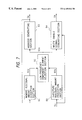
- FIG. 6 is a general system block diagram of a first embodiment of a compressed video data recording apparatus according to the present invention.
- FIG. 7 is a general system block diagram showing the internal configuration of a memory write control section in the embodiment of FIG. 6;
- FIG. 8 is a timing diagram for illustrating the basic principles of operation of the first embodiment
- FIG. 9 shows a recording track pattern of 15 tracks on which a GOP data unit has been recorded by a helical scan rotary recording head, and an additional track on which low-frequency component data have been recorded, by the first embodiment
- FIG. 10 shows another example of a recording track pattern which can be formed by a recording apparatus according to the present invention.
- FIG. 11 is a general system block diagram of a second embodiment of a compressed video data recording apparatus according to the present invention.
- FIG. 12 is a general system block diagram showing the internal configuration of a memory write control section in the second embodiment.
- FIG. 13 is a conceptual diagram for illustrating a compressed video data stream made up of data slices
- the elements of an I-picture i.e. successive sets of encoded quantized DCT coefficients corresponding to respectively blocks of picture elements of a block, occurring as sequential data
- the elements of an I-picture will be appear as a continuous sequence in the playback signal, in spite of the fact that an I-picture is recorded on a plurality of successively adjacent recording tracks. It would be possible to obtain a higher frequency of updating the display picture during high-speed playback if only a minimum necessary number of data elements (expressing low-frequency video signal components) sufficient to provide satisfactory display quality could be periodically read from the magnetic tape and used to update the display picture.
- a continuous sequence of such necessary data elements will not be obtained. That point is illustrated by FIG.
- the necessary minimum low-frequency video signal component elements that are contained in one I-picture of the compressed video data are indicated by the plurality of black portions 100 which are shown distributed throughout the recording tracks on which the I-picture is recorded.
- such low-frequency component data consist of respective sets of encoded coefficients which express low video frequency components for each of the DCT blocks of an I-picture (so that in actuality these would be represented to a much larger number of smaller black portions than those shown in FIG. 3 ). It can thus be understood that it would not be practical to selectively read such data from the magnetic tape during high-speed playback.
- the DCT coefficients are transmitted after having subjected to variable-length coding (i.e. run-length coding). It would be possible with the present invention to decode the DCT coefficients, then select a specific set of the DCT coefficients of an I-picture block which express the low-frequency component data, e.g. the DC coefficient and the two lowest-order AC coefficients. However in the following embodiments, it is assumed that, for each DCT block, the code for the DCT DC coefficient and the respective variable-length codes for the two lowest-order DCT AC coefficients are selected, as the low-frequency component data.
- FIG. 6 is a general system block diagram of a first embodiment of the invention.
- a digital video signal Sa expressing a stream of compressed video data is supplied to a demultiplexer and error correction section 1 .
- the demultiplexer and error correction section 1 demultiplexes the data of the input compressed video signal Sa, to extract information that is necessary for error correction, executes the error correction, and supplies a resultant error-corrected compressed video signal Sb to a discrimination information judgement section 5 .
- the discrimination information judgement section 5 detects syntax information (in this embodiment, MPEG syntax information) that is contained in the compressed video signal Sb and which relates to respective positions of video data elements within the data stream of signal Sb, and produces a corresponding discrimination information signal 5 a which indicates these data element timings.
- syntax information in this embodiment, MPEG syntax information
- “video data elements” signifies in particular each of the (encoded) DCT coefficients for each of the DCT blocks of a picture expressed in a stream of MPEG-1 compressed video data.
- the low-frequency component data for each DCT block will be assumed to be the code values of the three low-order DCT coefficients, i.e. the code for the DC coefficient and the variable-length codes for the two lowest-frequency AC coefficients.
- an EOB (End of Block) marker is then added, i.e. is written into the next memory address.
- the low-frequency component data will thereby be set in the same DCT block format as the other compressed video data, upon read-out from the memory 8 .
- the EOB markers could be successively attached while data are being read out from the memory 8 .
- the means for adding these EOB markers are not described in the following, since such means can easily be envisaged by a skilled person.
- FIG. 4 is a timing diagram in which diagram (A) illustrates the basic format of the compressed video data stream of signal Sa. This consists of successive compressed video data portions Da, each of which is preceded by a synchronizing information portion a 1 and an ID (identifier) information portion a 2 , and is followed by an error correction information portion a 3 .
- the demultiplexer and error correction section 1 utilizes the synchronizing information portions a 1 to detect the starting points of each of the compressed video data portions Da, then utilizes the corresponding error correction information portion a 3 to correct any errors within the compressed video data portion Da.
- the resultant digital video signal Sb is then subjected to time axis compression processing within the remaining circuits of FIG.
- the recording signal 9 a is supplied to a helical scan rotary recording head 52 , to be thereby recorded on a magnetic tape 53 .
- FIG. 6 can be modified by omitting the error correction function of the demultiplexer and error correction section 1 , i.e. by processing the digital video signal Sa directly, leaving the original synchronizing, ID and error correction portions a 1 , a 2 and a 3 within the digital data recording signal 9 a , together with the aforementioned new synchronizing, ID and error correction information portions b 1 , b 2 and b 3 .
- This is illustrated in the timing diagrams of FIG. 5, in which diagram (B) shows the basic form of the resultant recording signal 9 a.
- the recording signal 9 a further includes the aforementioned low-frequency component data, as described in the following.
- the compressed video data of the error-corrected digital video signal Sb are successively written into a memory 2 at a first data rate (i.e. the data rate of the compressed video signal Sb), then read out as successive fixed-length blocks from the memory 2 at a second data rate which is higher than the first data rate, such that fixed-length vacant intervals occur at regular intervals in the data stream output from the memory 2 .
- a clock signal CK 1 synchronized with the data of the compressed video data signal Sb, is extracted by the demultiplexer and error correction section 1 and used to control the timings of data write-in to two memories 2 and 8 .
- Fixed-length low-frequency component data blocks are read out from the memory 8 at the aforementioned regular intervals, and are respectively inserted into the aforementioned vacant intervals, to thereby form the recording signal 9 a .
- the blocks of low-frequency component data are thereby recorded on the magnetic tape 53 in each of regularly occurring fixed-duration intervals.
- the digital video signal Sb is supplied to the discrimination information judgement section 5 , which derives the aforementioned discrimination information as a discrimination information signal 5 a , which indicates the respective timings of all of the video data elements within the compressed video data of signal Sb, and a discrimination information signal 5 b which indicates the respective timings of the low-frequency component data.
- the discrimination information signal 5 a is also supplied together with the clock signal CK 1 to the write control section 3 , which generates successive write address values 3 a and a write enable signal 3 b , whereby respective elements of the compressed video data of signal Sb are written into successive addresses of the memory 2 at the first data rate (determined by clock signal CK 1 ).
- the write control section 3 operates, based on the discrimination information signal 5 a , such as to omit the aforementioned synchronizing, ID and error detection information portions a 1 , a 2 , a 3 from being written into the memory 2 .
- the discrimination information signal 5 b from the discrimination information judgement section 5 is supplied to a write control section 6 , which utilizes the discrimination information to determine the timings of data elements, within the data flow of the signal Sb, which constitute the low-frequency component data.
- the write control section 6 generates successive write address values 6 a and a write enable signal 6 b, at appropriate timings whereby the low-frequency component data are selected from the compressed video signal Sb by being written into respective addresses of the memory 8 .
- the discrimination information signal 5 a is further supplied to a read operation control section 50 , which generates control signals 50 a and 50 b , supplied to a read control section 4 and a read control section 7 respectively.
- the read control section 4 supplies read address values 4 a and a read enable signal 4 b to the memory 2
- the read control section 7 supplies read address values 7 a and a read enable signal 7 b to the memory 8 .
- the control signals 50 a , 50 b act on the read control section 4 and read control section 7 such as to ensure correct synchronization between the vacant intervals of the output data stream from the memory 2 and the intervals in which blocks of low-frequency component data are read out from the memory 8 .
- a timing signal generation section 51 generates a second clock signal CK 2 , having a higher frequency than the clock signal CK 1 , and a reference timing signal ST.
- the signals CK 2 and ST are supplied to a recording signal generating section 9 and to the read operation control section 50 , for controlling overall operation timings of these sections.
- the clock signal CK 2 is further supplied to the read control section 4 and to the read control section 7 as an operation clock signal, which determines the rate of data read-out from each of these memories.
- data are read out from the memory 2 at a second data rate which is higher than the aforementioned first data rate at which the data were written into the memory 2 .
- the data thus read out consist of successive fixed-length blocks of data, each formed of an integral number of sub-blocks such as the data portions 11 shown in diagram (B) of FIG. 4 .
- Such sub-blocks, each of which have the aforementioned synchronizing, ID and error correction information portions (which are necessary for the recording/playback process) then attached thereto by the recording signal generating section 9 will be referred to in the following as synchronizing blocks.
- the data stored in the memory 2 and memory 8 are preferably read out as sets of integral units of these synchronizing blocks, i.e. a low-frequency component data block which is read out from the memory 8 during one of the aforementioned vacant intervals of the data stream read out from the memory 2 will preferably consist of an integral number of synchronizing blocks.
- the data streams thus read out from the memory 2 and the memory 8 are combined into a single data stream by the recording signal generating section 9 , which assigns a set of the aforementioned synchronizing, ID and error correction information portions to each of the synchronizing blocks.
- Diagram (A) in FIG. 8 illustrates the general structure of the compressed video signal Sb, which is successively written into the memory 2 at the aforementioned first data rate, and which for simplicity of description is assumed to consist only of successive GOP units GOP 1 , GOP 2 , etc.
- the data which are actually written into the memory 2 are illustrated in diagram (B) of FIG. 8, showing that all of the compressed video data are written into the memory 2 .
- each of these sets can consist, for example, of the three low-order encoded DCT coefficients for a DCT block of an I-picture (with only three of the sets within each GOP unit being indicated in FIG. 8 ).
- Diagram (D) of FIG. 8 illustrates the recording signal 9 a which is derived by combining the data read out from the memory 2 and the memory 8 at the aforementioned second data rate.
- the plurality of low-frequency component data elements d 1 corresponding to the GOP unit GOP 1 which were written into the memory 8 , are read out from that memory as a single low-frequency component data block d 1 , which is inserted into a vacant interval that occurs between reading out two successive data blocks (GOP 1 and GOP 2 ) from the memory 2 .
- each of the data blocks which are read out from the memories 2 and 8 preferably consists of an integral number of the aforementioned synchronizing blocks.
- One of these synchronizing blocks, constituting part of the GOP unit GOP 0 after read-out from memory 2 is illustrated in diagram (E) of FIG. 8, with the aforementioned synchronizing, ID and error correction information portions b 1 , b 2 and b 3 having been attached thereto by the recording signal generating section 9 .
- FIG. 9 shows an example of the resultant track pattern which can be formed on the magnetic tape 53 by applying the recording signal 9 a of the form shown in diagram (D) of FIG. 8, via the rotary recording head 52 .
- each low-frequency component data block that is read out from the memory 8 comprises a minimum necessary amount of information for updating a display picture (for example, contains all of the sets of 3 low-order DCT coefficients of one I-picture).
- the first 15 tracks from the left correspond to the 15 tracks shown in FIG. 2, on which are recorded 15 successive pictures of a GOP data unit.
- the low-frequency component data block is recorded on an additional 16 th track, which is shown as track 101 in FIG. 9 . It can thus be understood that it now becomes possible, during high-speed playback, to efficiently read the low-frequency component data of respective I-pictures tracks such as track 101 , since these data can be recorded on respective periodically occurring tracks on the magnetic tape.
- the intra-coded data (from which the low-frequency component data are extracted) occur in the compressed video signal Sb in a fixed periodic manner, i.e. as periodically occurring I-pictures.
- the I-pictures will not occur in such a fixed periodic manner.
- Each such block may be, for example, data that are to fill one specific recording track of the magnetic tape, as in the example of FIG. 9 .
- FIG. 7 is a general system block diagram showing the internal configuration of the write control section 6 of the first embodiment. This is made up of an address generating section 63 which generates the address values 6 a and a write enable signal generating section 64 which generates the write enable signal 6 b , a memory residual amount detection section 61 which receives the address values 6 a , an I-picture residual amount prediction section 60 which receives the discrimination information signal 5 b , and a low frequency component element selection section 62 which is controlled by a combination of output signals 61 a and 60 a from the memory residual amount detection section 61 and I-picture residual amount prediction section 60 to produce a selection signal 62 a which is supplied to the address generating section 63 and write enable signal generating section 64 .
- the I-picture residual amount prediction section 60 functions to predict the amount of low-frequency component data which remains to be written into the memory 8 , (to complete the amount of low-frequency component data for one I-picture, i.e. the amount of data which is periodically read out as a block from memory 8 ).
- the output signal 60 a is indicative of that amount of data which has not yet been written into the memory 8 .
- the memory 8 is assumed to have only sufficient capacity to store aforementioned amount of low-frequency data for one I-picture.
- the memory residual amount detection section 61 detects the amount of vacant memory capacity remaining in the memory 8 , with the output signal 61 a being indicative of that remaining amount.
- the amounts expressed by these signals 61 a , 60 a are compared in the low frequency component element selection section 62 , whose output signal 62 a controls the address generating section 63 and write enable signal generating section 64 to write into the memory 8 the appropriate number of low-frequency component data, until the memory 8 becomes filled.
- the intra-coded data occur (as I-pictures) at regular intervals, while in the second case, the intra-coded data do not occur at regular intervals.
- the I-picture residual amount prediction section 60 need only count the number of DCT blocks (of an I-picture) that have been encountered, in relation to the total number of DCT blocks of an I-picture, to generate the indication signal 60 a .
- the I-picture residual amount prediction section 60 must use the average probability of occurrence of I-pictures within the compressed video signal Sb, and generate the signal 60 a such that the necessary amount of low-frequency video component data will be written into the memory 8 during each of the fixed intervals between read-out of the aforementioned low-frequency component data blocks from the memory 8 .
- a condition can occur whereby it will be predicted (based on the input signals 61 a , 60 a to the low frequency component element selection section 62 ) that the amount of low-frequency component data which will be acquired within an interval between read-out of one data block from the memory 8 and read-out of the suceeding block will be greater than the data block size, i.e. greater than the capacity of the memory 8 .
- the low frequency component element selection section 62 to control the writing of low-frequency component data into the memory 8 , i.e.:
- the amount o f data acquired for each DCT block can be reduced. That is, the low frequency component element selection section 62 can control data write-in to the memory 8 such that the number of DCT coefficient code values written into the memory 8 , for each DCT block, is reduced, or:
- FIG. 11 is a general system block diagram of a second embodiment of the invention.
- This embodiment differs from the first embodiment in the following respects.
- the overall compressed video data i.e. the data which are utilized during normal-speed playback of the VTR
- the low-frequency component data in a second memory.
- only a first memory is utilized for writing in the compressed video data (which of course include the low-frequency component data), while the addresses at which the low-frequency component data are stored in the first memory are written into a second memory.
- the compressed video data and the low-frequency component data are respectively read out from the first memory, at a higher data rate than that used during write-in, such as to be combined within a recording signal in the same manner as described for the first embodiment.
- the first memory (into which all of the compressed video data of signal Sb are successively written) is designated by numeral 2
- the second memory (into which are written the values of addresses where low-frequency component data are written into the memory 2 ) by numeral 12 .
- the input compressed video signal Sa are supplied to a demultiplexer and error correction section 1 , to obtain an error-corrected compressed video signal Sb which is supplied to a discrimination information judgement section 5 , and to generate a first clock signal CK 1 .
- the discrimination information judgement section 5 produces a discrimination information signal 5 a which indicates the timings of each of the elements of the compressed video data of signal Sb, and a discrimination information signal 5 a which indicates the timings of the low-frequency component data, which are to be selected from the compressed video data elements.
- the discrimination information signals 5 a , 5 b are supplied to a write control section 10 , while the discrimination information 5 a is also supplied to a read operation control section 57 .
- the write control section 10 generates address values 3 a and a write enable signal 3 b , which are supplied to the memory 2 to control write-in of the compressed video data of signal Sb at a first data rate, i.e.
- the write control section 10 generates address values 10 a and a write enable signal 10 b, which are supplied to the memory 12 , to control write-in of the values of addresses where the low-frequency component data elements are written into the memory 2 .
- address values are supplied from the write control section 10 , as signal 10 c , to be written into the memory 12 , in accordance with address values 10 a and write enable signal 10 b which are produced from the write control section 10 .
- the read control section 11 generates read address values 4 a and a read enable signal 4 b , which are supplied to the memory 2 , for reading out the overall compressed video data at second data rate, which is higher than the data rate at which compressed video data are written into the memory 2 , in the same way as for the first embodiment. However the read control section 11 further generates read address values 11 a and a read enable signal 11 b, which are supplied to the memory 12 . During each interval between reading out successive blocks of compressed video data from the memory 2 , the address values 10 c which have been written into the memory 12 are read out (at the second data rate) as consecutive sets of address values 11 c , which are supplied to the read control section 11 .
- the apparatus further includes a recording signal generating section 9 for receiving the data read out from the memory 2 , and producing a corresponding recording signal 9 a , a read operation control section 57 , and a timing signal generation section 51 which produces a second clock signal CK 2 and reference timing signal ST, which are supplied to the read operation control section 57 and recording signal generating section 9 for controlling operation timings of these sections.
- the clock signal CK 2 is also supplied to the read control section 11 , for setting the rate of data read-out from the memory 2 at a higher value than that of data write-in, in the same way as for the first embodiment.
- the read operation control section 57 produces a control signal 57 a which acts on the read control section 11 as follows.
- successive fixed-length blocks of compressed video data are read out from the memory 2 , in response to the address and read enable signals 4 a , 4 b generated by the read control section 11 , with fixed-length vacant intervals occurring between these blocks of compressed video data.
- the read control section 11 sequentially generates the address values of the memory 12 (as signal 11 a ), and correspondingly controls the read enable signal 11 b, so that the address values which have been written in the memory 12 are successively read out (as signal 11 c ) and transferred to the read control section 11 .
- the read control section 11 transfers these address values (as address values 4 a ) to the memory 2 , and correspondingly controls the read enable signal 4 b , so that a block of low-frequency component data (for example, the block d 0 shown in diagram (D) of FIG. 8) is read out from the memory 2 , and supplied to the recording signal generating section 9 .
- Section 11 then again begins to generate address values 4 a and the read enable signal 4 b for reading out the compressed video data from the memory 2 (e.g. block GOP 1 in diagram (D) of FIG. 8 ).
- Changeover between these two types of operation by the read control section 11 i.e. between the operation of internally generating address values for the compressed video data and the operation of reading out the low-frequency component data addresses from the memory 12 , is controlled by the signal 57 a from the read operation control section 57 .
- the compressed video data and low-frequency component data which are thus read out from the memory 2 and supplied to the recording signal generating section 9 are preferably read out in fixed-length synchronizing blocks (illustrated in diagram (E) of FIG. 8) which are appropriate for constituting the recording signal, and ID, synchronizing and error correction information portions are added to complete each of these synchronizing blocks by the recording signal generating section 9 , to thereby obtain the recording signal 9 a.
- FIG. 12 is a general system block diagram of the write control section 10 of the embodiment of FIG. 11 .
- This includes a portion, for generating the address and write enable signals 10 a , 10 b for the memory 12 , which has an identical configuration to that shown in FIG. 7 and described hereinabove. That portion consists of a memory residual amount detection section 61 , a I-picture residual amount prediction section 60 , a low frequency component element selection section 62 , an address generating section 63 and a write enable signal generating section 64 , for which further description will be omitted.
- the circuit of FIG. 12 further includes a gate circuit 100 which is controlled by the output signal 62 a from the low frequency component element selection section 62 , i.e.
- the circuit of FIG. 12 further includes an address generating section 110 and a write enable signal generating section 120 , which are controlled by the discrimination information signal 5 a from the discrimination information judgement section 5 , and which produce the write enable signal 3 a and the address values 3 b , respectively, which are used as described above for writing all of the compressed video data elements of signal Sb into the memory 2 .
- the address values 3 a are also supplied to the gate circuit 100 , whereby the addresses of the memory 2 into which the low-frequency component data are written are selected by the gate circuit 100 , and supplied (as the address values 10 c ) to be written into the memory 12 of the second embodiment.
- the intra-coded data only occurs in picture units, i.e. the I-pictures.
- the intra-coded data may occur in picture sub-units which are referred to as slices.
- the invention is equally applicable to such a type of compressed video data.
- the compressed video data can be written in the memory 2 as described for the first embodiment above.
- the elements of the low-frequency component data are selected from the I-slices as they occur, i.e.
- the discrimination information obtained from the MPEG syntax data can be used to specify respective data elements, i.e. specific DCT coefficients within respective DCT blocks at specific positions of a picture. So long as it is ensured that the blocks of low-frequency component data (for example, corresponding to the blocks d 0 , d 1 , etc. in diagram (D) of FIG.
- the memory 8 (or memory 12 ) functions as a buffer memory for the low-frequency component data, enabling fixed-size blocks of low-frequency component data to be inserted into the recording signal at appropriate timings.
- the essential features of the invention are that data which are essential for providing at least a minimum degree of recognition of a finally obtained display picture, referred to in the above as low-frequency component data, are extracted from the intra-coded data of a stream of compressed video data which represent successive pictures, that the compressed video data and low-frequency component data are each subjected to time axis compression and combined to obtain a data stream which is converted to a recording signal, and recorded on a magnetic tape.
- the time axis-compressed compressed video data and low-frequency component data are combined in such a manner that the low-frequency component data are recorded as successive blocks at positions on the recording track whereby during subsequent variable-speed playback of the recording track, the low-frequency component data can be effectively read from the recording track.
- the present invention as exemplified by the above embodiments has the following basic features:
- a continuous stream of compressed video data expressing respective pictures is supplied to a first memory, and successive fixed-size portions of the compressed video data are sequentially written into the first memory at a first data rate, and are sequentially read out from that memory at a second data rate which is higher than the first data rate. That data read-out is determined (i.e. in accordance with the difference between the first and second data rates) such that vacant time intervals of specific duration periodically occur in the output data flow from the first memory, at regular intervals.
- sets of low-frequency component data are selected from the compressed video data and written into a second memory (or a separate region of the first memory);
- the low-frequency component data are read out from the second memory as fixed-size blocks, at the second data rate, during the aforementioned vacant time intervals, and combined with the data read out from the first memory into a single data stream, which is processed to form a recording signal;
- the aforementioned time intervals are selected such that the low-frequency component data are recorded at specific positions on a recording track, these positions being predetermined such that the low-frequency component data can be effectively read from the magnetic tape during subsequent variable-speed playback operation.
- each low-frequency component data block must be read out at the appropriate timing to form a single track on the magnetic tape.
- the low-frequency component data selected from the intra-coded data of a GOP unit must be divided into a plurality of blocks, which are read out in intervals respectively timed such as to form recording track portions that are aligned with the path shown in FIG. 10 .
- Specific transport packets can be selected, as the low-frequency component data, and written into memory (e.g. memory 8 of the first embodiment above);
- the compressed video data are of course written into and read out from memory (e.g. in memory 2 of the first embodiment above), in the form of transport packets, so that the recording signal can be formed of a stream of compressed video data transport packets and low-frequency component data transport packets.
- the operation can be basically similar to that of either of the two embodiments described above.
- the invention successfully overcomes the problems of the prior art with regard to variable-speed playback of recorded compressed video data, enabling satisfactory display picture quality and rapid picture updating to be obtained during high-speed playback.
Landscapes
- Engineering & Computer Science (AREA)
- Signal Processing (AREA)
- Multimedia (AREA)
- Television Signal Processing For Recording (AREA)
- Signal Processing For Digital Recording And Reproducing (AREA)
Priority Applications (1)
| Application Number | Priority Date | Filing Date | Title |
|---|---|---|---|
| US09/259,688 US6169846B1 (en) | 1994-03-17 | 1999-03-01 | Compressed video data recording method and recording apparatus providing improved performance during variable-speed playback |
Applications Claiming Priority (5)
| Application Number | Priority Date | Filing Date | Title |
|---|---|---|---|
| JP6074265A JP2930089B2 (ja) | 1994-03-17 | 1994-03-17 | 圧縮映像情報記録方法及び圧縮映像情報記録装置 |
| JP6-74265 | 1994-03-17 | ||
| US40567595A | 1995-03-17 | 1995-03-17 | |
| US89915697A | 1997-07-23 | 1997-07-23 | |
| US09/259,688 US6169846B1 (en) | 1994-03-17 | 1999-03-01 | Compressed video data recording method and recording apparatus providing improved performance during variable-speed playback |
Related Parent Applications (1)
| Application Number | Title | Priority Date | Filing Date |
|---|---|---|---|
| US89915697A Continuation | 1994-03-17 | 1997-07-23 |
Publications (1)
| Publication Number | Publication Date |
|---|---|
| US6169846B1 true US6169846B1 (en) | 2001-01-02 |
Family
ID=13542130
Family Applications (1)
| Application Number | Title | Priority Date | Filing Date |
|---|---|---|---|
| US09/259,688 Expired - Lifetime US6169846B1 (en) | 1994-03-17 | 1999-03-01 | Compressed video data recording method and recording apparatus providing improved performance during variable-speed playback |
Country Status (4)
| Country | Link |
|---|---|
| US (1) | US6169846B1 (fr) |
| JP (1) | JP2930089B2 (fr) |
| KR (1) | KR100201231B1 (fr) |
| TW (1) | TW295660B (fr) |
Cited By (4)
| Publication number | Priority date | Publication date | Assignee | Title |
|---|---|---|---|---|
| US6542542B1 (en) * | 1999-01-29 | 2003-04-01 | Nec Corporation | I picture search apparatus and method |
| US20050276578A1 (en) * | 2002-12-26 | 2005-12-15 | Industrial Technology Research Institute | Real time data compression apparatus for a data recorder |
| US20100325243A1 (en) * | 2006-12-31 | 2010-12-23 | Wenping Zhang | Method and a system for realizing the interactive information through the multimedia |
| USD1054165S1 (en) * | 2021-09-20 | 2024-12-17 | Puma SE | Shoe |
Families Citing this family (1)
| Publication number | Priority date | Publication date | Assignee | Title |
|---|---|---|---|---|
| US7398005B2 (en) * | 2001-12-19 | 2008-07-08 | Thomson Licensing | Trick mode playback of recorded video |
Citations (12)
| Publication number | Priority date | Publication date | Assignee | Title |
|---|---|---|---|---|
| JPS61158633A (ja) | 1984-11-09 | 1986-07-18 | クイジナ−ツ インコ−ポレ−テツド | 安全スイツチ |
| US5140437A (en) | 1989-04-02 | 1992-08-18 | Sony Corporation | Recording/reproducing compressed data on a rotatable record medium in which at least one intraframe code signal and at least (n-1) interframe code signals are recorded in each track |
| US5253055A (en) * | 1992-07-02 | 1993-10-12 | At&T Bell Laboratories | Efficient frequency scalable video encoding with coefficient selection |
| US5329375A (en) * | 1991-02-26 | 1994-07-12 | Matsushita Electric Industrial Co., Ltd. | Information recording/reproducing apparatus |
| US5371602A (en) | 1988-06-13 | 1994-12-06 | Hitachi, Ltd. | Picture data recording/reproducing system for recording compressed picture data and reproducing recorded data with plural reproduction modes |
| US5410351A (en) * | 1991-07-31 | 1995-04-25 | Sony Corporation | Video signal transmission system and method |
| US5422736A (en) * | 1991-03-22 | 1995-06-06 | Canon Kabushiki Kaisha | Multi-mode image processing permitting selection of quantization process according to image characteristics |
| US5440345A (en) * | 1992-07-17 | 1995-08-08 | Kabushiki Kaisha Toshiba | High efficient encoding/decoding system |
| US5450209A (en) * | 1991-09-30 | 1995-09-12 | Kabushiki Kaisha Toshiba | Band-compressed signal processing apparatus |
| US5455684A (en) | 1992-09-22 | 1995-10-03 | Sony Corporation | Apparatus and method for processing a variable-rate coded signal for recording to provide a high-speed search capability, apparatus and method for reproducing such processed signal, and recording including such processed signal |
| US5510840A (en) | 1991-12-27 | 1996-04-23 | Sony Corporation | Methods and devices for encoding and decoding frame signals and recording medium therefor |
| US5576902A (en) | 1993-01-13 | 1996-11-19 | Hitachi America, Ltd. | Method and apparatus directed to processing trick play video data to compensate for intentionally omitted data |
Family Cites Families (2)
| Publication number | Priority date | Publication date | Assignee | Title |
|---|---|---|---|---|
| JPH05137114A (ja) * | 1991-11-14 | 1993-06-01 | Mitsubishi Electric Corp | デイジタルビデオテープレコーダ |
| JPH0662371A (ja) * | 1992-08-14 | 1994-03-04 | Matsushita Electric Ind Co Ltd | ディジタルvtr |
-
1994
- 1994-03-17 JP JP6074265A patent/JP2930089B2/ja not_active Expired - Fee Related
-
1995
- 1995-03-16 TW TW084102520A patent/TW295660B/zh active
- 1995-03-17 KR KR1019950005647A patent/KR100201231B1/ko not_active Expired - Fee Related
-
1999
- 1999-03-01 US US09/259,688 patent/US6169846B1/en not_active Expired - Lifetime
Patent Citations (13)
| Publication number | Priority date | Publication date | Assignee | Title |
|---|---|---|---|---|
| JPS61158633A (ja) | 1984-11-09 | 1986-07-18 | クイジナ−ツ インコ−ポレ−テツド | 安全スイツチ |
| US5371602A (en) | 1988-06-13 | 1994-12-06 | Hitachi, Ltd. | Picture data recording/reproducing system for recording compressed picture data and reproducing recorded data with plural reproduction modes |
| US5140437A (en) | 1989-04-02 | 1992-08-18 | Sony Corporation | Recording/reproducing compressed data on a rotatable record medium in which at least one intraframe code signal and at least (n-1) interframe code signals are recorded in each track |
| US5329375A (en) * | 1991-02-26 | 1994-07-12 | Matsushita Electric Industrial Co., Ltd. | Information recording/reproducing apparatus |
| US5422736A (en) * | 1991-03-22 | 1995-06-06 | Canon Kabushiki Kaisha | Multi-mode image processing permitting selection of quantization process according to image characteristics |
| US5410351A (en) * | 1991-07-31 | 1995-04-25 | Sony Corporation | Video signal transmission system and method |
| US5450209A (en) * | 1991-09-30 | 1995-09-12 | Kabushiki Kaisha Toshiba | Band-compressed signal processing apparatus |
| US5510840A (en) | 1991-12-27 | 1996-04-23 | Sony Corporation | Methods and devices for encoding and decoding frame signals and recording medium therefor |
| US5253055A (en) * | 1992-07-02 | 1993-10-12 | At&T Bell Laboratories | Efficient frequency scalable video encoding with coefficient selection |
| US5440345A (en) * | 1992-07-17 | 1995-08-08 | Kabushiki Kaisha Toshiba | High efficient encoding/decoding system |
| US5455684A (en) | 1992-09-22 | 1995-10-03 | Sony Corporation | Apparatus and method for processing a variable-rate coded signal for recording to provide a high-speed search capability, apparatus and method for reproducing such processed signal, and recording including such processed signal |
| US5568274A (en) | 1992-09-22 | 1996-10-22 | Sony Corporation | Apparatus and method for processing a variable-rate coded signal for erecording to provide a high-speed search capability, apparatus and method for reproducing such processed signal, and recording including such processed signal |
| US5576902A (en) | 1993-01-13 | 1996-11-19 | Hitachi America, Ltd. | Method and apparatus directed to processing trick play video data to compensate for intentionally omitted data |
Non-Patent Citations (2)
| Title |
|---|
| ISO/IEC International Standard 11172-2: 1993, Information Technology-Coding of Moving Pictures and Associated Audio for Digital Storage Media at up to About 1.5 Mbit/s-, pp.: 1-3, 5, 16, 27, 54, 85, 102 and 104. |
| Woo Paik, Digicipher-All Digital, Channel Compatible. IEEE tran., pp. 245-254, Dec. 1990.* |
Cited By (6)
| Publication number | Priority date | Publication date | Assignee | Title |
|---|---|---|---|---|
| US6542542B1 (en) * | 1999-01-29 | 2003-04-01 | Nec Corporation | I picture search apparatus and method |
| US20050276578A1 (en) * | 2002-12-26 | 2005-12-15 | Industrial Technology Research Institute | Real time data compression apparatus for a data recorder |
| US7623767B2 (en) * | 2002-12-26 | 2009-11-24 | Industrial Technology Research Institute | Real time data compression apparatus for a data recorder |
| US20100325243A1 (en) * | 2006-12-31 | 2010-12-23 | Wenping Zhang | Method and a system for realizing the interactive information through the multimedia |
| US9049498B2 (en) * | 2006-12-31 | 2015-06-02 | Xiaodong Yang | Method and system for realizing interaction of embedded data in multimedia |
| USD1054165S1 (en) * | 2021-09-20 | 2024-12-17 | Puma SE | Shoe |
Also Published As
| Publication number | Publication date |
|---|---|
| JPH07264544A (ja) | 1995-10-13 |
| KR100201231B1 (ko) | 1999-06-15 |
| TW295660B (fr) | 1997-01-11 |
| JP2930089B2 (ja) | 1999-08-03 |
| KR950028502A (ko) | 1995-10-18 |
Similar Documents
| Publication | Publication Date | Title |
|---|---|---|
| EP0627855B1 (fr) | Enregistrement de signaux vidéo numériques | |
| KR960002393B1 (ko) | 영상신호기록재생장치 | |
| EP0683611B1 (fr) | Un appareil d'enregistrement et de reproduction numérique | |
| US5786858A (en) | Method of encoding image signal, apparatus for encoding image signal, method of decoding image signal, apparatus for decoding image signal, and image signal recording medium | |
| US6314137B1 (en) | Video data compression system, video recording/playback system, and video data compression encoding method | |
| EP0778703A2 (fr) | Dispositif d'enregistrement/reproduction de codes longueur variable | |
| EP0728396B1 (fr) | Enregistrement et reproduction d'un signal video numerique sous forme de donnees reduites sur un support d'enregistrement longitudinal | |
| US6061495A (en) | Apparatus and method for recording and/or reproducing picture data operable to output zeros if a picture header is detected during variable speed reproduction | |
| US6275618B1 (en) | Apparatus for and method of processing images | |
| US7006760B1 (en) | Processing digital data having variable packet lengths | |
| KR0185932B1 (ko) | 고속재생을 위한 비디오데이타 복호방법 및 그 장치 | |
| KR100796885B1 (ko) | 신호 프로세서 | |
| KR100302027B1 (ko) | 최소하나의테이프헤드를가진디지탈비디오레코더및이레코더를이용한화상데이타기록방법 | |
| KR100975170B1 (ko) | 화상 데이터 재생 장치 및 방법 | |
| JP3253530B2 (ja) | 動画像記録装置 | |
| US6169846B1 (en) | Compressed video data recording method and recording apparatus providing improved performance during variable-speed playback | |
| KR0154890B1 (ko) | 화상신호 복호화방법 및 화상신호 복호화장치 | |
| US20020071491A1 (en) | Signal processor | |
| JP3852114B2 (ja) | 圧縮画像データ伝送方法及び装置 | |
| US5892883A (en) | Recording of a data reduced digital video signal in slant tracks on a record carrier | |
| US20040101051A1 (en) | Image processing apparatus and method for processing motion-picture data and still-image data | |
| JP3304634B2 (ja) | ディジタル信号再生装置 | |
| US6201926B1 (en) | Apparatus for recording digital picture signal | |
| JPWO1996007273A1 (ja) | 圧縮画像データ伝送方法及び装置 | |
| EP0969471A2 (fr) | Milieu d'enregistrement d'information et appareil d'édition et méthode associée |
Legal Events
| Date | Code | Title | Description |
|---|---|---|---|
| FEPP | Fee payment procedure |
Free format text: PAYOR NUMBER ASSIGNED (ORIGINAL EVENT CODE: ASPN); ENTITY STATUS OF PATENT OWNER: LARGE ENTITY |
|
| STCF | Information on status: patent grant |
Free format text: PATENTED CASE |
|
| CC | Certificate of correction | ||
| FPAY | Fee payment |
Year of fee payment: 4 |
|
| FPAY | Fee payment |
Year of fee payment: 8 |
|
| FPAY | Fee payment |
Year of fee payment: 12 |
|
| AS | Assignment |
Owner name: RAKUTEN, INC., JAPAN Free format text: ASSIGNMENT OF ASSIGNORS INTEREST;ASSIGNOR:OHISHI, TAKEO;REEL/FRAME:031133/0930 Effective date: 20130826 |